2014 VOLKSWAGEN TRANSPORTER ice warning
[x] Cancel search: ice warningPage 246 of 486
Inserting the Euro plug
• Plug the Euro plug into the Euro socket. The child safety function will disengage at the same time. Electricity will not flow until the child lock has been unlocked.
• Push the Euro plug all the way into the Euro socket so that it is firmly in place and will not fall out as a result of vibration or other vehicle motion.
LEDs above the socket
Constant green light The child lock is disen-gaged. The Euro socket is ready for use.
Flashing red light A fault has occurred. for example cut-off due to excess current or tem-perature.
Compatible devices
Electrical devices with a Euro plug can be connec-ted to the 230-volt Euro socket in the side trim pan-el behind the left front seat.
230-volt grounded safety socket
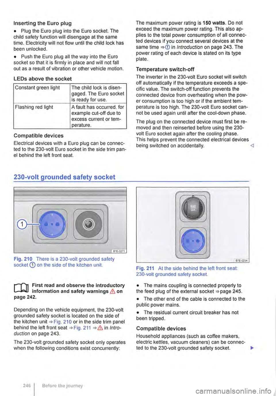
Fig. 210 There is a 230-volt grounded safety socket Q) on the side of the kitchen unit.
r--T'n First read and observe the Introductory L-k.U information and safety warnings & on page 242.
Depending on the vehicle equipment, the 230-volt grounded safety socket is located on the side of the kitchen unit 210 or in the side trim panel behind the left front seat 211 Intro-duction on page 243.
The 230-volt grounded safety socket only operates when the following conditions exist concurrently:
246 I Before the journey
The maximum power rating is 150 watts. Do not exceed the maximum power rating. This also ap-plies to the total power consumption of all connec-ted devices if you connect several devices at the same time in Introduction on page 243. The power rating of each device is stated on its type plate.
Temperature switch-off
The inverter in the 230-volt Euro socket will switch off automatically if the temperature exceeds a spe-cific value. The switch-off function prevents the connected device from overheating when the pow-er consumption is too high or if the ambient tem-perature is too high. The 230-volt Euro socket can-not be used again until after the cool-down phase.
The plug on the connected device must first be re-moved and then reinserted before using the 230-volt Euro socket again after the cooling phase. This helps prevent the connected electrical devices being switched on accidentally. <1
B7E.Q29.4
Fig. 211 At the side behind the left front seat: 230-volt grounded safety socket.
• The mains coupling is connected properly to the feed plug of the external socket 245.
• The other end of the cable is connected to the public power mains.
• The residual current circuit breaker has not been tripped.
Compatible devices
Household appliances (such as coffee makers, electric kettles, vacuum cleaners) can be connec-ted to the 230-volt grounded safety socket. .,.
Page 247 of 486
The maximum power rating is 2500 watts. Do not exceed the maximum power rating. This also ap-plies to the total power consumption of all connec-ted devices if you connect several devices at the
Residual current circuit breaker
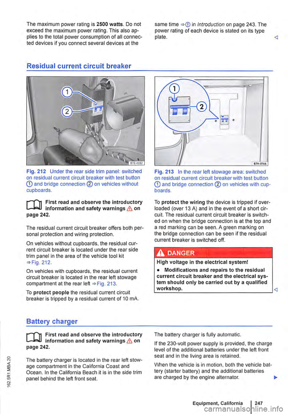
Fig. 212 Under the rear side trim panel: switched on residual current circuit breaker with test button CD and bridge connection ®on vehicles without cupboards.
r-f'n First read and observe the introductory L..-.lo:-ll information and safety warnings & on page 242.
The residual current circuit breaker offers both per-sonal protection and wiring protection.
On vehicles without cupboards, the residual cur-rent circuit breaker is located under the rear side trim panel in the area of the vehicle tool kit 212.
On vehicles with cupboards, the residual current circuit breaker is located in the rear left stowage compartment at the rear left 213.
To protect people the residual current circuit breaker is tripped by a residual current of 10 mA.
Battery charger
r-f'n First read and observe the Introductory L..-.lo:-ll information and safety warnings & on page 242.
The battery charger is located in the rear left stow-age compartment in the California Coast and Ocean. In the California Beach it is in the side trim panel behind the left front seat.
same time in Introduction on page 243. The power rating of each device is stated on its type plate.
Fig. 213 In the rear left stowage area: switched on residual current circuit breaker with test button CD and bridge connection ® on vehicles with cup-boards.
To protect the wiring the device is tripped if over-loaded (over 13 A) and in the event of a short cir-cuit. The residual current circuit breaker is switch-ed on when the bridge connection is at the top and a red marking can be seen. A green marking on the bridge connection can be seen if the residual current breaker is switched off.
High voltage in the electrical system!
• Modifications and repairs to the residual current circuit breaker and the electrical sys-tem should only be carried out by a qualified workshop.
If the 230-volt power supply is provided, the charge level of the additional batteries under the left front seat and in the living area is retained.
When the vehicle is in motion, both the vehicle bat-tery (starter battery) and the additional batteries are charged by the engine alternator.
Equipment, California I 247
Page 252 of 486

A WARNING
Never program the supplementary heating system so that Is switched on and run In un-ventilated or enclosed areas. The fumes from the supplementary heating system contain carbon monoxide, which is an odourless and
Practical tips, California
o::n Introduction
This chapter contains information on the following subjects:
Before setting off . . . . . . . . . . . . . . . . . . . . . . . . 252 Before you take a road trip . . . . . . . . . . 252
Actions to take during thunderstorms 253
Winter conditions . . . . . . . . . . . . . . . . . . 253
Cleaning cupboards, cooker and sink . 253
Cleaning the display of the central control panel . . . . . . . . . . . . . . . . . . . . 254
Before setting off
rl'"'n First read and observe the introductory L..J.:.U Information given on page 252.
Checklist
The following points should be verified in addition to the checklist 33:
..( Close the pop-up roof .
..( Close all drawers, cabinet doors and flaps.
Before you take a road trip
rl'"'n First read and observe the Introductory L..J.:.U Information given on page 252.
Checklist
Observe the following additional suggestions:
../
../
Familiarise yourself with parking and ma-noeuvring the vehicle.
Note the height and width of the vehicle-particularly if any accessories have modified these dimensions.
2521 Before tho journoy
A WARNING (Continued)
colourless poisonous gas. Carbon monoxide can cause people to lose consciousness. it can also cause death.
m All saved switch-on times will be deleted if W you switch off the central control panel or dis-connect the additional battery. They will also be de-leted ifthere is a defective fuse in the control pan-el.
Rectifying faults on the camping equipment . . 254
Technical data. living area . . 255
Additional information:
• Central control panel 204.
• Before setting off =:>page 33.
• Vehicle care and maintenance 380.
..( Retract the awning completely.
..( Remove all vehicle interior shades and open all blinds.
..( Bring all tables into their stowed position .
../ Close all gas shut-off valves.
/ Secure all loose items in the vehicle. _., ______________________________
../
../
../
Check that all items of equipment are in good working order .
Observe the entry and vaccination require-ments of any foreign country you will be vis-iting.
Have the following documents on hand:
-Valid identity cards or passports
-Driving licence and vehicle registration papers ..,.
Page 264 of 486
Dual clutch gearbox DSG®
r-('n First read and observe the Introductory L-.lo:on Information and safety warnings & on page 260.
Description
The DSG® dual clutch gearbox is a gearbox which uses dual-clutch technology to change gear automatically. it uses a dual clutch and two independent gearboxes to enable very fast gear changes with no loss of torque. The DSG® dual clutch gearbox thus combines the performance and economy of a manual gearbox with the com-fort and convenience of a conventional automatic transmission.
How the system works
Engine power is transferred to the drive shafts via the gearbox. In order to change gears, the power transmission between the engine and the gearbox has to be interrupted. This is what the clutch is for.
With the DSG® dual clutch system with its two complementary gearboxes, one gearbox is always connected under load to the engine. When one gear is engaged, another gear is always preselec-
led in the other gearbox. The clutch on the non-driven gear is closed and the other is opened at the same time. This is what makes very fast gear changes possible.
The DSG® dual clutch gearbox is designed to be more efficient than an automatic gearbox. In an au-tomatic gearbox, the torque converter is constantly in use, whereas in the DSG® dual clutch system the idle clutch can be opened, thus saving fuel. With its efficiency, low weight and intelligent control system, the DSG® dual clutch system usually ena-bles fuel consumption equal to or lower than a manual gearbox.
like the manual gearbox, the clutch in the DSG dual clutch system is subject to wear. Regular maintenance is necessary, varying accord-ing to what type of DSG® dual clutch system is in-stalled. For more information see the service schedule. In the DSG® dual clutch system, if one gearbox malfunctions it is deactivated and the oth-er gearbox functions alone *page 267. If this happens, have the system checked as soon as possible by a qualified workshop.
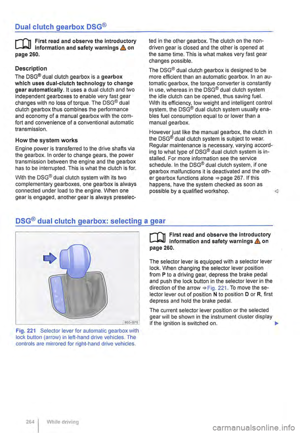
Fig. 221 Selector lever for automatic gearbox with lock button (arrow) in left-hand drive vehicles. The controls are mirrored for right-hand drive vehicles.
264 I While driving
r-('n First read and observe the Introductory L-.lo:on Information and safety warnings & on page 260.
The selector lever is equipped with a selector lever lock. When changing the selector lever position from P to a driving gear, depress the brake pedal and push the lock button in the selector lever in the direction of the arrow *Fig. 221. To move the se-lector lever out of position N to position D or R, first depress and hold the brake pedal.
The current selector lever position or the selected gear will be shown in the instrument duster display if the ignition is switched on. .,..
Page 273 of 486
heavy load on the brakes should be avoided. For example, when driving too close to the vehicle ahead.
The rate of wear of the brake pads depends to a great extent on the conditions under which the ve-hicle is operated and the way in which the vehicle is driven. With regular urban trips, short journeys and a sporty driving style, the brake pads must be checked by a qualified workshop more regularly than stated in the service schedule.
When driving with wet brakes, for example after driving through water, after heavy rainfall or after washing the vehicle, the braking effect may be de-layed as the brake discs will be wet, or possibly ic-ed up (in winter). The brakes must be "dried" as quickly as possible by careful braking at higher speed. Ensure that no vehicle behind you or no other road user is put at risk as a result of this ac-
Any salt layer accumulating on the discs and pads will delay the braking effect and increase the braking distance. If the brakes on the vehicle have not been applied for a long time on roads that have been gritted with salt, the layer of salt must be re-duced through careful braking &.
Corrosion on the brake discs and dirt in the brake pads are facilitated through long periods of inactivi-ty, low mileage and low load levels. With inactivity or low use levels for the brake pads as well as cor-rosion, Volkswagen Commercial Vehicles recom-mends that the brake discs and brake pads be cleaned by braking strongly several times from high speed. Ensure that no vehicle behind you or no other road user is put at risk as a result of this
Fault in the brake system
A brake circuit may have failed if you have to re-duce speed and the vehicle does not brake as nor-mal (sudden increase in braking distance). This will be indicated by the warning lamp m and in some cases a text message. Go to the nearest qualified workshop immediately to have the fault corrected. Drive at low speed when doing this and anticipate much longer braking distances and an increase in the pressure required on the pedal.
Brake servo
The brake serve will only function when the engine is running and reinforces the pressure applied by the driver on the brake pedal.
If the brake serve is not functioning or the vehicle is being towed, the brake pedal will have to be de-pressed more forcefully as the braking distance will be increased due to the lack of assistance for the brake system &.
A WARNING
New brake pads will not have the optimal braking effect when first fitted.
• New brake pads cannot generate the full braking effect during the first 300 km and must first be run In. A reduced braking effect can be Increased by applying more pressure to the brake pedal.
• You must drive particularly carefully when driving with new brake pads In order to re-duce the risk of accidents, serious Injuries and loss of control of the vehicle.
• Never drive too close to other vehicles when running in new brake pads, and never create a driving situation that will place a heavy load on the brakes.
A WARNING
Overheated brakes reduce the braking effect and considerably Increase the braking dis-tance.
• When driving downhill the brakes are placed under particular strain and become hot very quickly.
• Before driving down a long, steep gradi-ent, reduce speed and change to a lower gear or move the selector lever to a lower position. This will make use of the engine braking ef-fect and relieve the load on the brakes.
• Non-standard or damaged front spoilers could restrict the airflow to the brakes and cause them to overheat.
A WARNING
Wet brakes or brakes coated with ice or road salt react more slowly and require longer braking distances.
• Carefully apply the brakes to test them.
• Always dry brakes and clean off any coat-Ing of Ice and salt with a few cautious appli-cations of the brake when visibility, weather, road and traffic conditions permit.
A WARNING
Driving without the brake servo can consider-ably Increase the braking distance and thus cause accidents and serious Injuries.
• Never allow the vehicle to roll if the engine Is switched off.
Starting the engine, changing gear and parking 273
Page 276 of 486
A WARNING (Continued)
• Although the brake support systems are very effective and can help to control the ve-hicle in difficult driving situations, please al-ways remember that the driving stability of the vehicle depends on the tyre grip.
• When accelerating on a slippery surface, for example on ice and snow, press the accel-erator carefully. The wheels can spin even when brake support systems are active, and this can lead to a loss of control of the vehl-cl e.
A WARNING
ESC will be considerably less effective if oth· er components and systems that affect driv-ing dynamics are not serviced correctly or are not functioning properly. This also ap-plies, but not exclusively, to the brakes, tyres and other systems that have already been named.
Switching the TCS on and off
BSO·OC40
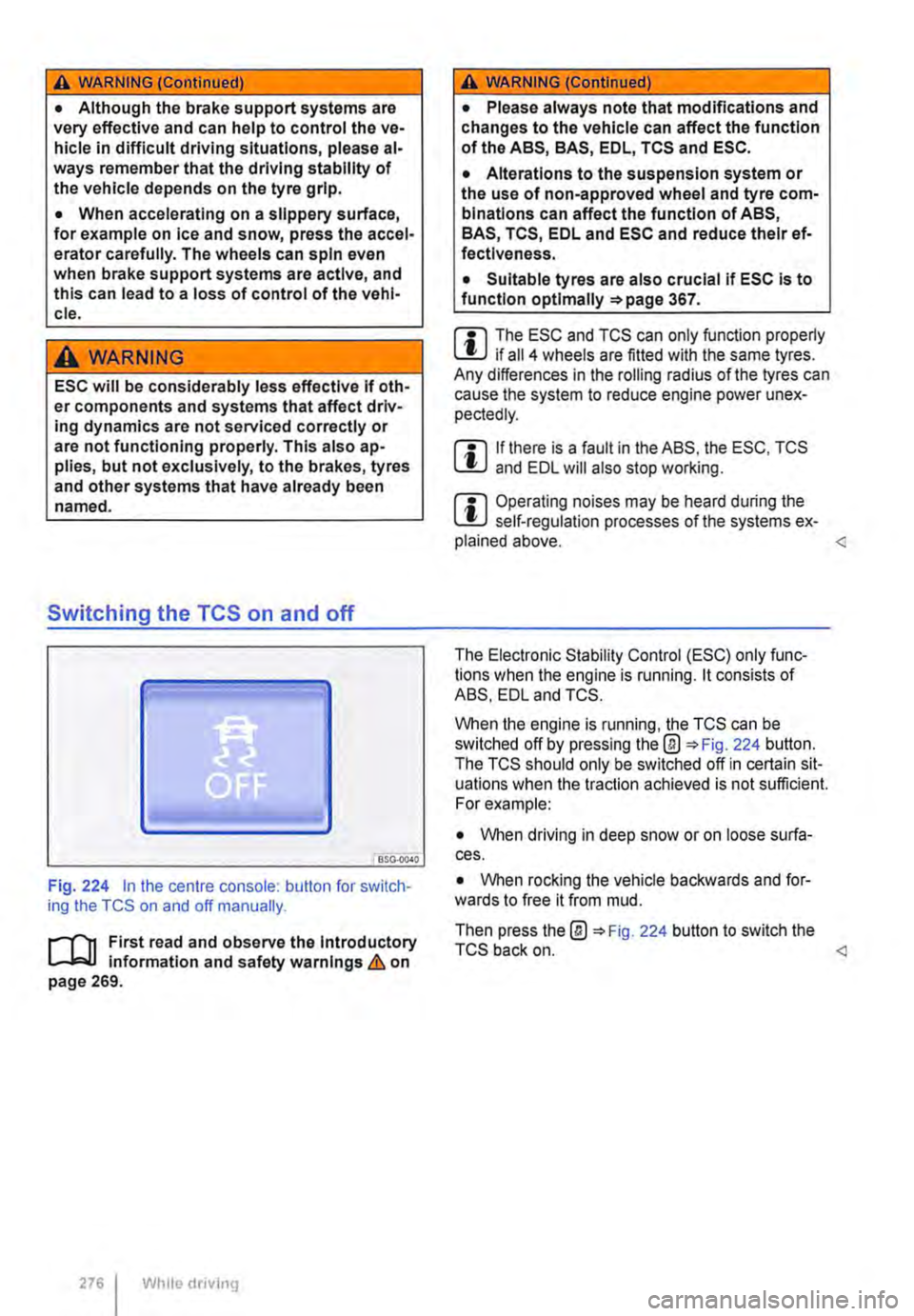
Fig. 224 in the centre console: button for switch-ing the TCS on and off manually.
.-m First read and observe the introductory l-J=J.I information and safety warnings & on page 269.
276 Wh1lo driving
A WARNING (Continued)
• Please always note that modifications and changes to the vehicle can affect the function of the ABS, BAS, EDL, TCS and ESC.
• Alterations to the suspension system or the use of non-approved wheel and tyre com-binations can affect the function of ABS, BAS, TCS, EDL and ESC and reduce their ef· fectiveness.
• Suitable tyres are also crucial if ESC is to function optlmaliy =>page 367.
m The ESC and TCS can only function properly L.:U if ail 4 wheels are fitted with the same tyres. Any differences in the roiling radius of the tyres can cause the system to reduce engine power unex-pectedly.
m If there is a fault in the ABS, the ESC, TCS lU and EDL will also stop working.
m Operating noises may be heard during the L.:U self-regulation processes of the systems ex-plained above.
When the engine is running, the TCS can be switched off by pressing the@ 224 button. The TCS should only be switched off in certain sit-uations when the traction achieved is not sufficient. For example:
• When driving in deep snow or on loose surfa-ces.
• When rocking the vehicle backwards and for-wards to free it from mud.
Then press the@ 224 button to switch the TCS back on.
Page 277 of 486
Brake fluid
B7E.02AO
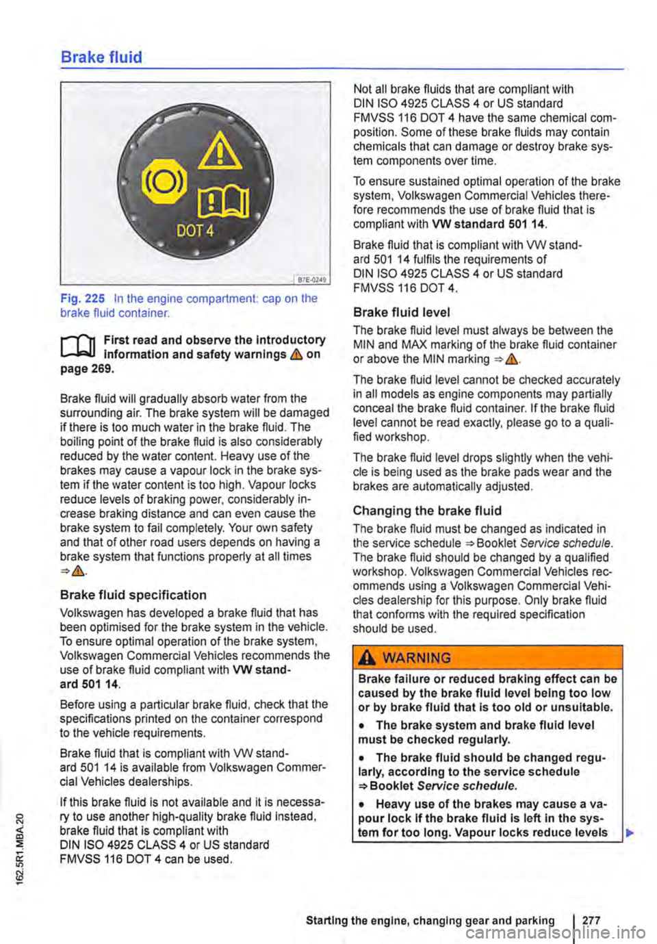
Fig. 225 In the engine compartment: cap on the brake fluid container.
r-111 First read and observe the Introductory l-Jr:,U Information and safety warnings&. on page 269.
Brake fluid will gradually absorb water from the surrounding air. The brake system will be damaged if there is too much water in the brake fluid. The boiling point of the brake fluid is also considerably reduced by the water content. Heavy use of the brakes may cause a vapour lock in the brake sys-tem if the water content is too high. Vapour locks reduce levels of braking power, considerably in-crease braking distance and can even cause the brake system to fail completely. Your own safety and that of other road users depends on having a brake system that functions properly at all times
Brake fluid specification
Volkswagen has developed a brake fluid that has been optimised for the brake system in the vehicle. To ensure optimal operation of the brake system, Volkswagen Commercial Vehicles recommends the use of brake fluid compliant with VW stand-ard 501 14.
Before using a particular brake fluid, check that the specifications printed on the container correspond to the vehicle requirements.
Brake fluid that is compliant with VW stand-ard 501 14 is available from Volkswagen Commer-cial Vehicles dealerships.
If this brake fluid is not available and it is necessa-ry to use another high-quality brake fluid instead, brake fluid that is compliant with DIN ISO 4925 CLASS 4 or US standard FMVSS 116 DOT 4 can be used.
Not all brake fluids that are compliant with DIN ISO 4925 CLASS 4 or US standard FMVSS 116 DOT 4 have the same chemical com-position. Some of these brake fluids may contain chemicals that can damage or destroy brake sys-tem components over time.
To ensure sustained optimal operation of the brake system, Volkswagen Commercial Vehicles there-fore recommends the use of brake fluid that is compliant with VW standard 501 14.
Brake fluid that is compliant with VW stand-ard 501 14 fulfils the requirements of DIN ISO 4925 CLASS 4 or US standard FMVSS 116 DOT 4.
Brake fluid level
The brake fluid level must always be between the MIN and MAX marking of the brake fluid container or above the MIN marking &.
The brake fluid level cannot be checked accurately in all models as engine components may partially conceal the brake fluid container. If the brake fluid level cannot be read exactly, please go to a quali-fied workshop.
The brake fluid level drops slightly when the vehi-cle is being used as the brake pads wear and the brakes are automatically adjusted.
Changing the brake fluid
The brake fluid must be changed as indicated in the service schedule Service schedule. The brake fluid should be changed by a qualified workshop. Volkswagen Commercial Vehicles rec-ommends using a Volkswagen Commercial Vehi-cles dealership for this purpose. Only brake fluid that confonns with the required specification should be used.
A WARNING
Brake failure or reduced braking effect can be caused by the brake fluid level being too low or by brake fluid that Is too old or unsuitable.
• The brake system and brake fluid level must be checked regularly.
• The brake fluid should be changed regu-larly, according to the service schedule Service schedule.
• Heavy use of the brakes may cause a va-pour lock If the brake fluid Is left In the sys-tem for too long. Vapour locks reduce levels
Starting the engine, changing gear and parking I 277
Page 278 of 486
A WARNING (Continued)
of braking power, considerably increase brak-ing distance and can cause the brake system to fail completely.
• Please ensure that the correct brake fluid is used. Only use brake fluid that Is explicitly compliant with VW standard 501 14.
• Any other brake fluid or a low-quality one can affect the functioning of the brakes and reduce their effectiveness.
• If a brake fluid compliant with VW stand-ard 501 14 Is not available, use a high-quality brake fluid compliant with DIN ISO 4925 CLASS 4 or the US standard FMVSS 116 DOT 4, but only in exceptional circumstances.
• The refilled brake fluid must be new .
A wARNING
Brake fluid is toxic.
• In order to reduce the risk of poisoning, never use bottles or other containers to store brake fluid. These containers could encour-age other people to drink out of them, even if they are labelled otherwise.
• Brake fluid must always be stored in its original sealed container and kept out of the reach of children.
CD
Brake fluid that has leaked or been split can damage the vehicle palntwork, plastic parts and tyres. Brake fluid that has leaked or been split should be cleaned off the vehicle paint-work and other components Immediately.
& Brake nuid can pollute the environment. Any W spilt service nuids must be cleaned up and disposed of properly.
o:::n Introduction
This chapter contains information on the following subjects:
An economic driving style . . . . . . . . . . . . . . . . . 278
Saving fuel . . . . . . . . . . . . . . . . . . . . . . . . . . . . . 280
Fuel consumption, environmental impact and wear on the engine, brakes and tyres depend largely on three factors:
• Personal driving style.
• Conditions of use (weather, road surface).
• Technical conditions.
An economic driving style
i""1"'n First read and observe the introductory L-J,:.U information and safety warnings & on page 278. .,.
278 I While drivmg
A few simple measures can help save fuel by up to 25%, depending on how you drive.
A WARNING
Adapt your speed and distance from the vehi-cles ahead to suit visibility, weather, road and traffic conditions.