2014 VOLKSWAGEN TRANSPORTER ECU
[x] Cancel search: ECUPage 133 of 486
Guide rail system in the rear vehicle floor
CQJ Introduction
This chapter contains information on the following subjects:
Opening and closing the rail system 133
Fastening rings in the rail system . . . . 134
T-shaped fastening ring . . . . . . . . . 135
Net partition . . . . . . . . . . . . . . . . . . . . . . 136
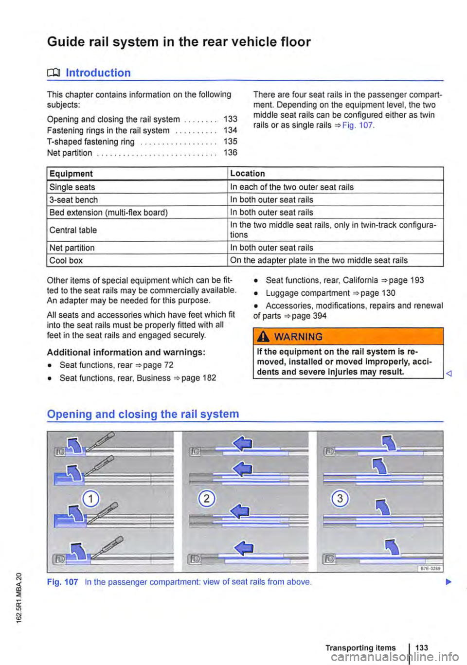
There are four seat rails in the passenger compart-ment. Depending on the equipment level, the two middle seat rails can be configured either as twin rails or as single rails =>Fig. 107.
Equipment Location
Single seats In each of the two outer seat rails
3-seat bench In both outer seat rails
Bed extension (multi-flex board) In both outer seat rails
Central table In the two middle seat rails, only in twin-track configura-lions
Net partition In both outer seat rails
Cool box On the adapter plate in the two middle seat rails
Other items of special equipment which can be fit-ted to the seat rails may be commercially available. An adapter may be needed for this purpose.
All seats and accessories which have feet which fit into the seat rails must be properly fitted with all feet in the seat rails and engaged securely.
Additional information and warnings:
• Seat functions, rear =>page 72
• Seat functions, rear, Business =>page 182
• Seat functions, rear, California =>page 193
• Luggage compartment =>page 130
• Accessories, modifications, repairs and renewal of parts =>page 394
A WARNING
If the equipment on the rail system Is re-moved, Installed or moved Improperly, acci-dents and severe Injuries may result
Transporting items 133
Page 134 of 486
t"""""fl1 First read and observe the introductory l..--bll information and safety warnings & on page 133.
Removing plastic covers
The plastic covers=:. Fig. 107 must be removed from the seat rails, if seats or the central table are to be installed or removed.
• Take the screwdriver from the vehicle tootkit.
• Insert the flat blade of the screwdriver into the seat rail at an angle in front of the plastic cover you wish to remove G).
• Press the cover lug approx. 3 mm to the front and, at the same time, lever it out.
Removing split cover rail
• Grasp with both hands into the rubber lip of the shorter part (approx. 30 cm) of the aluminium cov-er rail ®. and push it towards the front until both clips are released.
• Remove cover rail@ upwards in a straight line.
• Now, also move the opposite part of the alumi-nium cover rail towards the front, and remove it up-wards in a straight line.
• Repeat this procedure for all seat rails.
Installing split cover rail
• Fit the aluminium cover rail so that it is flush with the longer part of the cover rail.
• Push the aluminium cover rail from above into the clips of the seat rail until it engages.
• Repeat this procedure for all seat rails.
Fastening rings in the rail system
Fig. 108 Fastening ring in the seat rail.
1> daN: Deka Newton. Unit for load carrying capacity.
134 Before the JOUrney
Installing plastic covers
• Insert the plastic cover CD with the recess at the front into the seat rail and press down at the back until the cover engages securely. The cover must be flush with the seat rails.
• Ensure that the plastic covers for the double seat rails are not confused with each other as the covers will otherwise not engage securely.
A WARNING
If the equipment In the seat rails Is removed, Installed or moved Improperly, accidents and severe Injuries may result.
• Proceed with care when removing and In-stalling the aluminium cover rails: risk of In-jury caused by corners and edges.
• The aluminium cover rails and plastic cov-ers must always be Installed when the vehicle Is In motion.
• Never remove the seat rails completely. Such jobs should only be carried out by a qualified workshop.
• If your seat rails are damaged, have them checked, and If necessary replaced, by a qualified workshop.
CD
If seats are moved when the seat rails are soiled, the seat rails and the seat feet could be damaged.
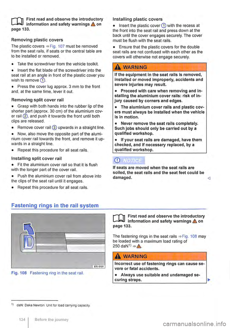
The fastening rings in the seat rails ::.Fig. 108 may be loaded with a maximum load rating of 250 daN1l ::.&.
A wARNING
Incorrect use of fastening rings can cause se-vere or fatal accidents.
• Always use suitable and undamaged se-curing straps. ..,.
Page 135 of 486
A WARNING (Continued)
• Attach securing straps securely to the fas-tening rings.
• Loose objects in the vehicle can suddenly slide and change the way the vehicle han-dles.
• Never exceed the maximum load rating of the fastening rings when securing objects.
• Small and light objects should also be se-cured.
• Never secure a child seat to the fastening rings.
• Rotating single seats must always be turned in the direction of travel if a load is se-cured behind this seat using fastening rings.
T-shaped fastening ring
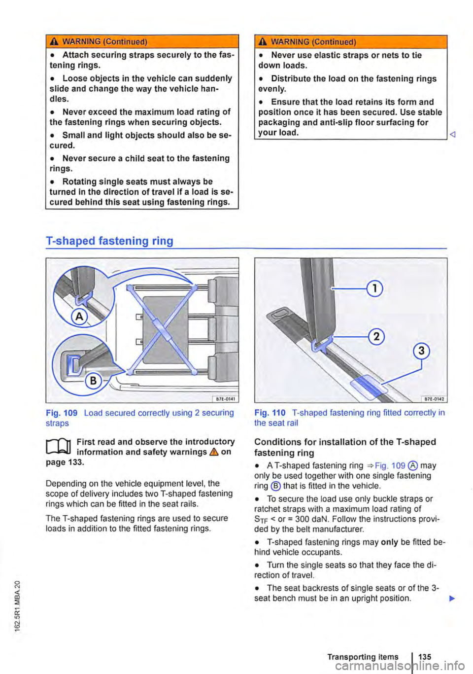
Fig. 109 Load secured correctly using 2 securing straps
il11 First read and observe the introductory L-J,.:.U information and safety warnings & on page 133.
Depending on the vehicle equipment level, the scope of delivery includes two T-shaped fastening rings which can be fitted in the seat rails.
The T-shaped fastening rings are used to secure loads in addition to the fitted fastening rings.
A WARNING (Continued)
• Never use elastic straps or nets to tie down loads.
• Distribute the load on the fastening rings evenly.
• Ensure that the load retains its form and position once it has been secured. Use stable packaging and anti-slip floor surfacing for your load.
Conditions for installation of the T-shaped fastening ring
• AT-shaped fastening ring 109 ®may only be used together with one single fastening ring® that is fitted in the vehicle.
• To secure the load use only buckle straps or ratchet straps with a maximum load rating of SrF < or= 300 daN. Follow the instructions provi-ded by the belt manufacturer.
• T-shaped fastening rings may only be fitted be-hind vehicle occupants.
• Turn the single seats so that they face the di-rection of travel.
• The seat backrests of single seats or of the 3-seat bench must be in an upright position. .,.
Transporting Items 135
Page 136 of 486
Fitting the T-shaped fastening ring
• Fit the T-shaped fastening ring parallel to the seat rail in the seat rail.
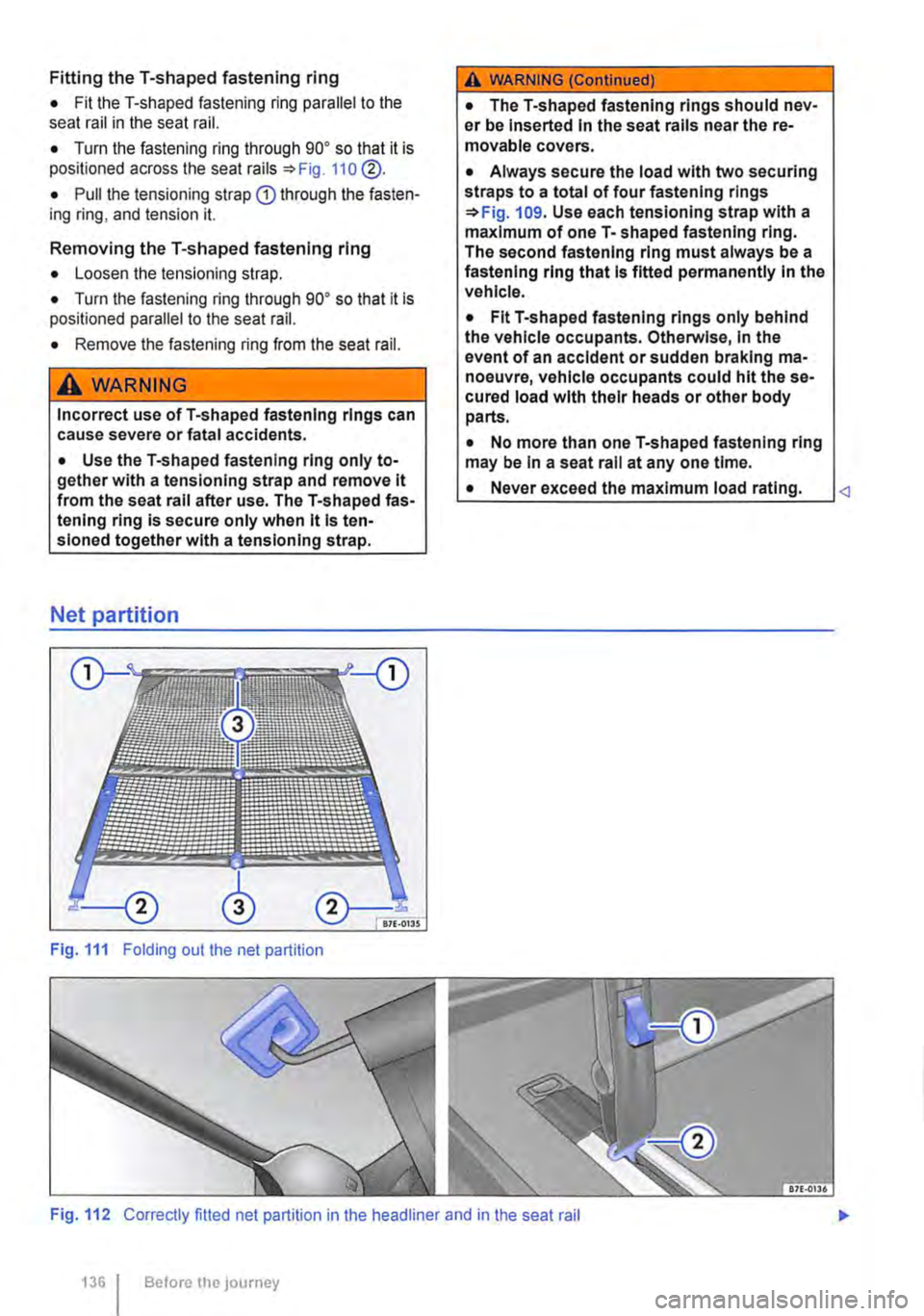
• Turn the fastening ring through go• so that it is positioned across the seat rails =:>Fig. 110 @.
• Pull the tensioning strap Q) through the fasten-ing ring, and tension it.
Removing the T-shaped fastening ring
• Loosen the tensioning strap.
• Turn the fastening ring through go• so that it is positioned parallel to the seat rail.
• Remove the fastening ring from the seat rail.
A WARNING
Incorrect use ofT-shaped fastening rings can cause severe or fatal accidents.
• Use the T-shaped fastening ring only to-gether with a tensionlng strap and remove it from the seat rail after use. The T-shaped fas-tening ring is secure only when it Is ten-sloned together with a tenslonlng strap.
Net partition
Fig. 111 Folding out the net partition
A WARNING (Continued)
• The T-shaped fastening rings should nev-er be Inserted In the seat rails near the re-movable covers.
• Always secure the load with two securing straps to a total of four fastening rings =:>Fig. 109. Use each tensloning strap with a maximum of one T-shaped fastening ring. The second fastening ring must always be a fastening ring that Is fitted permanently In the vehicle.
• Fit T-shaped fastening rings only behind the vehicle occupants. Otherwise, In the event of an accident or sudden braking ma-noeuvre, vehicle occupants could hit the se-cured load with their heads or other body parts.
• No more than one T-shaped fastening ring may be In a seat rail at any one time.
• Never exceed the maximum load rating.
1361 Before the journey
Page 137 of 486
n11 First read and observe the introductory l-J=,IJ information and safety warnings & on page 133.
The net partition can prevent objects in the lug-gage compartment entering the passenger com-partment.
The net partition can be fitted behind the front seats or behind the 3-seat bench.
Key to Fig. 111:
® Cross pieces with joints which lock into place
Preparing the net partition for fitting
• Take the net partition out of its plastic bag and unroll it fully.
• Fold out all the side rods fully, until you hear a "clicking• noise.
Fitting the net partition
• Make sure that the sewn-in instructions label is pointing to the rear.
• Hook the net partition up onto the left-hand side
• Push the rod together to hook the net partition onto the right-hand side.
• Pull the net partition to check that it has engag-ed securely in the retainers in the headliner.
• On the left and right sides. pull the strap down on the loop G) until you can insert the T-shaped holder into the outer seat rails.
• Turn each of the T-shaped holders through 90° so that they are positioned across the seat rails @.
• Make sure that the net partition is vertical and securely fitted in the seat rails.
Roof carrier
COl Introduction
This chapter contains information on the following subjects:
Attaching the mounts and roof carrier . . . . . . . 138 Loading the roof carrier . . . . . . . . . . . . . . . . . . . 139
Removing the net partition
• Slacken off the straps by pulling loop
• Push the net partition on one side slightly to the inside of the vehicle and lift it out of the upper re-tainer.
• Press the release button 111 ® in the joint of each cross piece and fold the cross pieces together.
• Roll up the net partition and stow it in its plastic bag.
• Stow the plastic bag securely in the vehicle.
A WARNING
Always use the net partition carefully, observ-Ing the Instructions. Risk of injury.
• The net partition is secured properly in the roof only if the T-shaped holders are securely fitted Into the retainers.
• The net partition is fitted correctly in the seat rails only if the T-shaped retainers are at right-angles to the seat rails and correctly en-gaged.
• The T-shaped holders must never be fitted close to the removable covers on the seat rails.
• Heavy, pointed or sharp items which are not stowed securely can cause Injury in the event of sudden braking manoeuvres or acci-dents. This may also happen when the net partition is fitted correctly.
• Vehicle occupants must not travel behind a fitted safety net.
• When it is no longer being used.
• When the vehicle is driving through a car wash.
• When the vehicle height exceeds the required clearance height, e.g. in a garage. .,.
Transporting items 1137
Page 138 of 486
Additional information and warnings:
• Lights 106
• Transporting 125
• Driving with respect for the environment 278
• Wheels and tyres 367
• Accessories, modifications, repairs and renewal of parts 394
A wARNING
When transporting heavy or bulky objects in the roof carrier, the vehicle's handling will change due to a shift in the centre of gravity and an increased susceptibility to cross-winds.
• Always secure loads properly using suita-ble and undamaged securing straps.
• Cargo that is large, heavy, bulky, long or flat will have a negative effect on the vehicle aerodynamics, centre of gravity and overall handling.
Attaching the mounts and roof carrier
r-Y'n First read and observe the introductory L-J,:.JJ information and safety warnings &. on page 137.
Your vehicle has special roof rails on the right and left for fitting the mounts. Therefore, standard roof carriers cannot be used. Volkswagen Commercial Vehicles recommends using only mounts and roof carriers that have been approved by Volkswagen Commercial Vehicles.
The mounts are the basis of a complete roof carrier system. Special fixtures must then be added to transport luggage, bicycles, skis, surfboards or boats safely on the roof. All components of this system are available at a Volkswagen Commercial Vehicles dealership.
The roof carrier system must always be installed exactly according to instructions and should be kept with the vehicle wallet.
138 I Before the journey
A WARNING (Continued)
• Avoid abrupt and sudden driving and braking manoeuvres.
• Always adapt your speed and driving style to suit visibility, weather, road and traffic con-ditions.
CD
• Always remove the roof carrier before driv-ing through an automatic car wash.
• The height of the vehicle is changed by the installation of a carrier system and the load se-cured to it. Check and compare the height of the vehicle with clearance heights, e.g. for un-derpasses and garage doors.
• The roof carrier system and its load must not obstruct you from opening and closing the sliding/tilting roof and tallgate. The roof aerial must also remain unaffected.
• When opening the tallgate, take care not to let it hit the roof load.
Driving with a fitted roof carrier will increase W air resistance and thus increase fuel con-sumption.
Incorrectly attaching the mounts and roof carrier, and using them Inappropriately, can cause the whole system to fail off the roof. This can cause accidents and injuries.
• Always observe the manufacturer's in-structions.
• Only use mounts and roof carriers when they are undamaged and fitted correctly.
• Fit mounts and roof carriers correctly.
• Check the bolts and anchorage points be-fore starting your journey and adjust as nec-essary after driving a short distance. During a long trip, check ail bolts and fasteners at each stop.
• Special fixtures for items such as bicy-cles, skis, surfboards, etc. should always be properly Installed.
• Do not carry out any alterations or repairs to the mounts and roof carrier.
W Read and observe the instructions provided L!J for the fitted roof carrier system and carry them in the vehicle at all times.
Page 139 of 486
Loading the roof carrier
ill1 First read and observe the introductory L-l.:.l.l information and safety warnings & on page 137.
Loads can only be attached securely when the roof carrier system is fitted correctly &.
Maximum permissible roof load
The maximum permissible roof load for vehicles with a normal roof is 150 kg and for vehicles with a pop-up roof it is 50 kg. The roof load limit refers to the combined weight of the roof carrier and the load carried on the roof &.
Each mount can bear a maximum load of 50 kg if the weight of the load is evenly distributed over the entire length of the mount.
Ensure that you know the weight of the roof rack and the items to be transported on the roof, and weigh them if necessary. Never exceed the maxi-mum permissible roof load.
However, you will not be able to carry the maxi-mum roof load if you are using a roof carrier with a lower weight rating. In this instance, do not exceed the maximum weight limit for the roof carrier. This weight limit is listed in the fitting instructions.
Distributing the load
Distribute the load evenly and secure it correctly
Checking the fittings
After the mounts and roof carrier have been at-tached, check the bolted connections and fasten-ings once you have travelled a short distance and then at regular intervals.
Towing a trailer
o:n Introduction
This chapter contains information on the following subjects:
Technical requirements . . . . . . . . . . 141 Fitting the removable ball coupling 142
Removing the ball coupling . . . . . . . . . 144
Hitching and connecting the trailer . . . 144 Loading the trailer . . . . . . . . . .. . . 146 Towing a trailer . . . . . . . . . . . . . . . . . . . . . . . . 146
Trailer stabilisation . . . . . . . . . . . . . . . . . . . . . . 147
Retrofitting a towing bracket............... 149
A WARNING
Accidents and vehicle damage can occur if the maximum permitted roof load is excee-ded.
• Never exceed the quoted roof load, the maximum permissible axle loads, and the permissible gross vehicle weight for the vehi-cle.
• Do not exceed the weight rating of the roof carrier, even if the maximum roof load has not been reached.
• Secure heavy objects as far forwards as possible and distribute the load evenly.
A WARNING
Loose and Incorrectly secured loads can fall off the roof carrier and cause accidents and injuries.
• Always use suitable and undamaged se-curing straps.
• Secure loads properly.
The additional load will affect the durability, fuel consumption and performance of the vehicle and, in certain circumstances, could shorten the service intervals.
Driving with a trailer not only places an extra load on the vehicle, but also requires increased concen-tration on the part of the driver.
Transporting items 139
Page 140 of 486
In low temperatures, fit winter tyres to both the ve-hicle and the trailer.
Drawbar load
The drawbar load is the weight that the towing bracket exerts on the ball coupling vertically from above. The maximum permitted weight exerted by the trailer drawbar on the ball coupling of the tow-ing bracket must not exceed 100 kg.
The figures for the draw bar weights that are given on the type plate of the towing bracket are for cer-tification purposes only. The correct values for your specific model, which may be lower than these fig-ures, are given in the vehicle registration docu-ments. All data in the official vehicle documents take precedence over these data &.
In the interest of road safety, Volkswagen Commer-cial Vehicles recommends that you always trans-port the maximum drawbar load. The response of the trailer on the road will be poor if the drawbar load is too small.
The drawbar load increases the weight on the rear axle and reduces the maximum load level as a re-sult.
Vehicles with starUstop system
• If a factory-fitted towing bracket or a towing bracket retro-fitted by Volkswagen Commercial Ve-hicles is used, the Start/Stop system remains ac-tive when towing a trailer 283.
• If towing brackets that were not retrofitted by Volkswagen Commercial Vehicles are used, the StarUStop system must be switched off manually using the button in the dash panel before you start towing a trailer and must remain switched off as long as a trailer is being towed &.
Tachograph
For vehicles whose gross vehicle weight rating, in-cluding trailer exceeds 3,500 kg, and those used commercially to transport goods, use of a tacho-graph is required by law. This is irrespective of whether the vehicle or the trailer or both are used for commercial transportation of goods.
Additional information and warnings:
• Exterior views 5
• Lights 106
• Tachograph 172
• Braking, stopping and parking 269
• Driving with respect for the environment 278
• Wheels and tyres 367
• Accessories, modifications, repairs and renewal of parts 394
140 Before the journey
• Maximum permitted trailer weights =>page 450
• Maximum permitted gross combination weight rating =>page 450
A WARNING
it is dangerous to transport people In a trailer and it may also be illegal.
A WARNING
Improper use of the towing bracket can cause Injury and accidents.
• Only use the towing bracket if it Is fitted properly and Is not damaged.
• Do not carry out any alterations or repairs to the towing bracket.
• To reduce the risk of Injury In rear-end col· lis ions, and to pedestrians and cyclists when the vehicle Is parked, always remove the ball coupling when a trailer Is not being used.
• Never Install a weight-distributing or load-balancing towing bracket to the vehicle. The vehicle Is not constructed for these kinds of towing brackets. The towing bracket can fall, causing the trailer to tear loose from the vehl· cl e.
A WARNING
Towing a trailer and transporting heavy or bulky Items can change the way the vehicle's handling. This can lead to accidents.
• Always secure loads properly using suita-ble and undamaged securing straps.
• Always adapt your speed and driving style to suit visibility, weather, road and traffic con-ditions.
• Trailers with a high centre of gravity are more likely to tip over than trailers with a low centre of gravity.
• Avoid abrupt and sudden driving and braking manoeuvres.
• Take special care when overtaking.
• Reduce your speed Immediately if the trailer shows even the slightest sign of snak-Ing.
• Never drive faster than 80 km/h (50 m ph) when towing a trailer or 100 km/h (62 mph) In exceptional cases. This also applies to coun-tries where higher speeds are permitted. AI· ways obey speed limits. In some areas speed limits for vehicles that are towing trailers are lower than for vehicles without trailers. .,.