2014 VAUXHALL MOVANO_B towing
[x] Cancel search: towingPage 80 of 201
78Instruments and controlsTurn signal
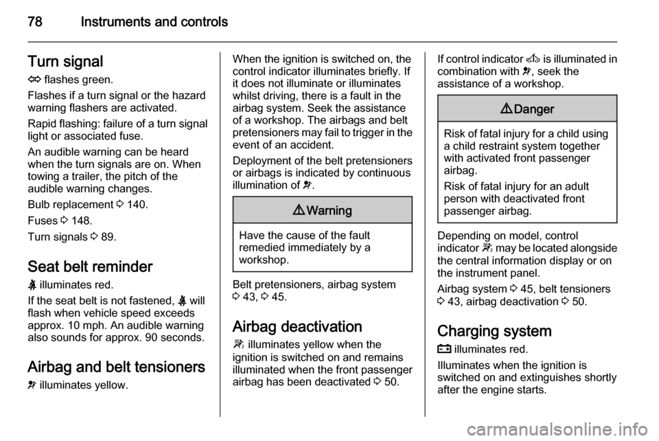
O flashes green.
Flashes if a turn signal or the hazard
warning flashers are activated.
Rapid flashing: failure of a turn signal light or associated fuse.
An audible warning can be heard
when the turn signals are on. When
towing a trailer, the pitch of the
audible warning changes.
Bulb replacement 3 140.
Fuses 3 148.
Turn signals 3 89.
Seat belt reminder
X illuminates red.
If the seat belt is not fastened, X will
flash when vehicle speed exceeds
approx. 10 mph. An audible warning
also sounds for approx. 90 seconds.
Airbag and belt tensioners
v illuminates yellow.When the ignition is switched on, the
control indicator illuminates briefly. If
it does not illuminate or illuminates
whilst driving, there is a fault in the
airbag system. Seek the assistance
of a workshop. The airbags and belt
pretensioners may fail to trigger in the event of an accident.
Deployment of the belt pretensioners
or airbags is indicated by continuous
illumination of v.9 Warning
Have the cause of the fault
remedied immediately by a
workshop.
Belt pretensioners, airbag system
3 43, 3 45.
Airbag deactivation
W illuminates yellow when the
ignition is switched on and remains
illuminated when the front passenger
airbag has been deactivated 3 50.
If control indicator A is illuminated in
combination with v, seek the
assistance of a workshop.9 Danger
Risk of fatal injury for a child using
a child restraint system together
with activated front passenger
airbag.
Risk of fatal injury for an adult
person with deactivated front
passenger airbag.
Depending on model, control
indicator W may be located alongside
the central information display or on
the instrument panel.
Airbag system 3 45, belt tensioners
3 43, airbag deactivation 3 50.
Charging system
p illuminates red.
Illuminates when the ignition is
switched on and extinguishes shortly
after the engine starts.
Page 115 of 201

Driving and operating113Caution
Fuel grades other than those listedon page 3 127, 3 174 could
damage the catalytic converter or
electronic components.
Unburnt petrol will overheat and
damage the catalytic converter.
Therefore avoid excessive use of the starter, running the fuel tank
dry and starting the engine by
pushing or towing.
In the event of misfiring, uneven
engine running, a reduction in engine performance or other unusual
problems, have the cause of the fault
rectified by a workshop as soon as
possible. In an emergency, driving
can be continued for a short period,
keeping vehicle speed and engine
speed low.
If control indicator Z flashes, the
permitted emission limits may be
exceeded. Lift your foot off the
accelerator until Z stops flashing and
is steadily illuminated. Contact a
workshop immediately.
Malfunction indicator light 3 79.Manual transmission
To engage reverse, with the vehicle
stationary depress the clutch pedal, pull up the collar on the selector lever
and engage the gear.
If the gear does not engage, set the
lever in neutral, release the clutch
pedal and depress again; then repeat
gear selection.
Do not slip the clutch unnecessarily.
When operating, depress the clutch pedal completely. Do not use the
pedal as a foot rest.
Page 119 of 201
Driving and operating117
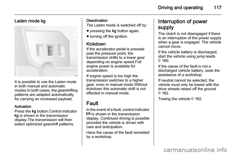
Laden mode kg
It is possible to use the Laden mode
in both manual and automatic
modes.In both cases, the gearshifting
patterns are adapted automatically
for carrying an increased payload.
Activation
Press the kg button.Control indicator
kg is shown in the transmission
display.The transmission will then
select optimized gearshift patterns.
Deactivation
The Laden mode is switched off by:
■ pressing the kg button again,
■ turning off the ignition.
Kickdown If the accelerator pedal is pressedpast the pressure point, the
transmission shifts to a lower gear
depending on engine speed.Full
engine power is available for
acceleration.
If engine speed is too high the
transmission switches to a higher
gear, even in manual mode.Without
kickdown this automatic shift is not
effected in manual mode.
Fault In the event of a fault, control indicator
W is shown in the transmission
display. Continued driving is possible
provided the vehicle is driven with
care and anticipation.
Have the cause of the fault remedied
by a workshop.Interruption of power
supply The clutch is not disengaged if there
is an interruption of the power supply
when a gear is engaged. The vehicle
cannot move.
If the vehicle battery is discharged,
start the vehicle using jump leads
3 160.
If the cause of the fault is not a discharged vehicle battery, seek the
assistance of a workshop.
If neutral cannot be selected, the
vehicle must only be towed with the drive wheels raised off the ground
3 162.
Towing the vehicle 3 162.
Page 131 of 201

Driving and operating129Trailer hitch
General information
Only use towing equipment that has
been approved for your vehicle.
Entrust fitting of towing equipment at
a later date to a workshop. It may be
necessary to make changes that
affect the cooling system, heat
shields or other equipment.
Driving characteristics and
towing tips In the case of trailers with brakes,
attach the breakaway stopping cable.
Before attaching a trailer, lubricate
the coupling ball. However, do not do
so if a stabiliser, which acts on the
coupling ball, is being used to reduce snaking movements. For trailers with
low driving stability the use of a
stabiliser is recommended.
A maximum speed of 50 mph must
not be exceeded, even in countries
where higher speeds are permitted.If the trailer starts snaking, drive more
slowly, do not attempt to correct the
steering and brake sharply if
necessary.
When driving downhill, drive in the
same gear as if driving uphill and
drive at a similar speed.
Adjust tyre pressure to the value
specified for full load 3 189.
Trailer towing Trailer loads
The permissible trailer loads are
vehicle-dependent and engine-
dependent maximum values which
must not be exceeded. The actual trailer load is the difference between
the actual gross weight of the trailer
and the actual coupling socket load
with the trailer coupled.
The permissible trailer loads are
specified in the vehicle documents. In general, they are valid for gradients
up to max. 12 %.
The permitted trailer load applies up to the specified incline and up to an
altitude of 1000 metres above sealevel. Since engine power decreases
as altitude increases due to the air
becoming thinner, therefore reducing
climbing ability, the permissible gross
train weight also decreases by 10 %
for every 1000 metres of additional
altitude. The gross train weight does
not have to be reduced when driving
on roads with slight inclines (less than
8 %, e.g. motorways).
The permissible gross train weight
must not be exceeded. This weight is
specified on the identification plate
3 171.
Vertical coupling load
The vertical coupling load is the load
exerted by the trailer on the coupling
ball. It can be varied by changing the
weight distribution when loading the
trailer.
The maximum permissible vertical
coupling load is specified on the
towing equipment identification plate
and in the vehicle documents. Always aim for the maximum load, especially
in the case of heavy trailers. The
vertical coupling load should never
fall below 25 kg.
Page 132 of 201
130Driving and operating
In the case of trailer loads of
1200 kg or more, the vertical coupling load should not be less than 50 kg.
Rear axle load
When the trailer is coupled and the
towing vehicle fully loaded (including all occupants), the permissible rear
axle load (see identification plate or
vehicle documents) must not be
exceeded.
Towing equipmentCaution
When operating without a trailer,
remove the coupling ball bar.
Towing equipment audible
warning For vehicles fitted with towing
equipment, when connected to a
trailer the pitch of the audible warning
changes upon operation of the turn
signals.
The pitch of the audible warning will
change if a turn signal light on the
trailer or the towing vehicle fails.Auxiliary features
Power take-off
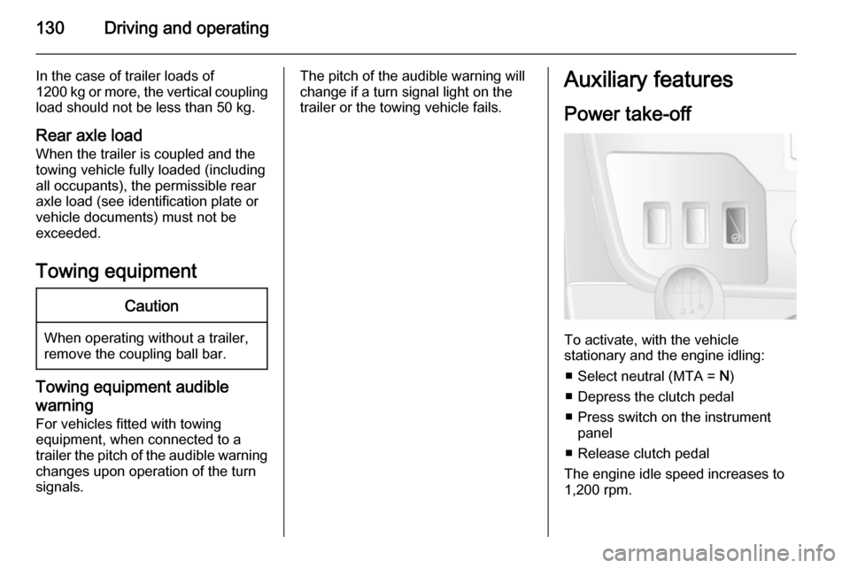
To activate, with the vehicle
stationary and the engine idling:
■ Select neutral (MTA = N)
■ Depress the clutch pedal
■ Press switch on the instrument panel
■ Release clutch pedal
The engine idle speed increases to 1,200 rpm.
Page 134 of 201

132Vehicle careVehicle careGeneral Information...................132
Vehicle checks ........................... 133
Bulb replacement .......................140
Electrical system ........................148
Vehicle tools .............................. 150
Wheels and tyres .......................151
Jump starting ............................. 160
Towing ....................................... 162
Appearance care .......................164General Information
Accessories and vehicle
modifications
We recommend the use of genuine parts and accessories and factory
approved parts specific for your
vehicle type. We cannot assess or
guarantee reliability of other products
- even if they have a regulatory or
otherwise granted approval.
Do not make any modifications to the electrical system, e.g. changes of
electronic control units (chip tuning).
Vehicle storage Storage for a long period of time
The following tasks must be carried
out if the vehicle is to be stored for several months:
■ Wash and wax the vehicle.
■ Have the wax in the engine compartment and underbody
checked.
■ Clean and preserve rubber seals.■ Change engine oil.
■ Drain washer fluid reservoir.
■ Check coolant antifreeze.
■ Adjust tyre pressure to the value specified for full load.
■ Park vehicle in a dry, well ventilated
place.Engage first or reverse
gear.Prevent the vehicle from
rolling.
■ Do not apply parking brake.
■ Open bonnet, close all doors and lock the vehicle.
■ Disconnect the clamp from the negative terminal of the vehicle
battery.Beware that all systems are
not functional, e.g. anti-theft alarm
system.
Putting back into operation
The following tasks must be carried
out if the vehicle is being put back into operation:
■ Connect the clamp to the negative terminal of the vehicle
battery.Activate the electronics of
the power windows.
■ Check tyre pressure.
Page 152 of 201
150Vehicle care
SymbolCircuitZInfotainment system, seat
heating, vehicle display
screen, audio connections,
alarm?Power outletÌCigarette lightereInstrument panelUCentral lockingOTurn signals, rear fog lights, body control moduleDIAGDiagnostic connectoruABS, Electronic stability
programdInterior lights, brake lightsZBody control moduleSTOPBrake lightIBody control module, power windows, air conditioningmLeft heated rear windowSymbolCircuitnRight heated rear windowRWindscreen washerMElectronic immobiliserUHeated seatsFBLCornering lightlHands-free connection&TachographPTOPower take-offjHornÍPreheating, diesel fuel filterxClimate control fanADPAdditional adaptations,Power windows, body
control moduleVehicle tools
Tools
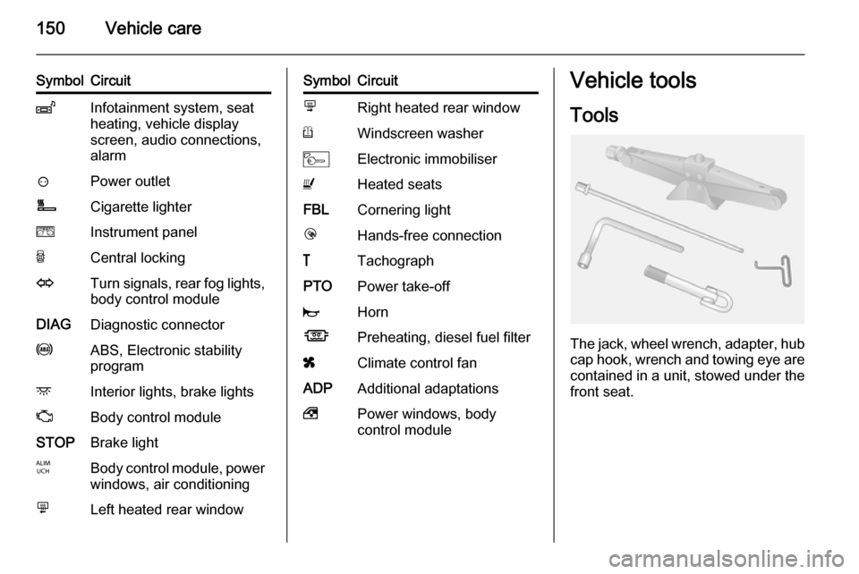
The jack, wheel wrench, adapter, hubcap hook, wrench and towing eye are
contained in a unit, stowed under the front seat.
Page 164 of 201
162Vehicle care
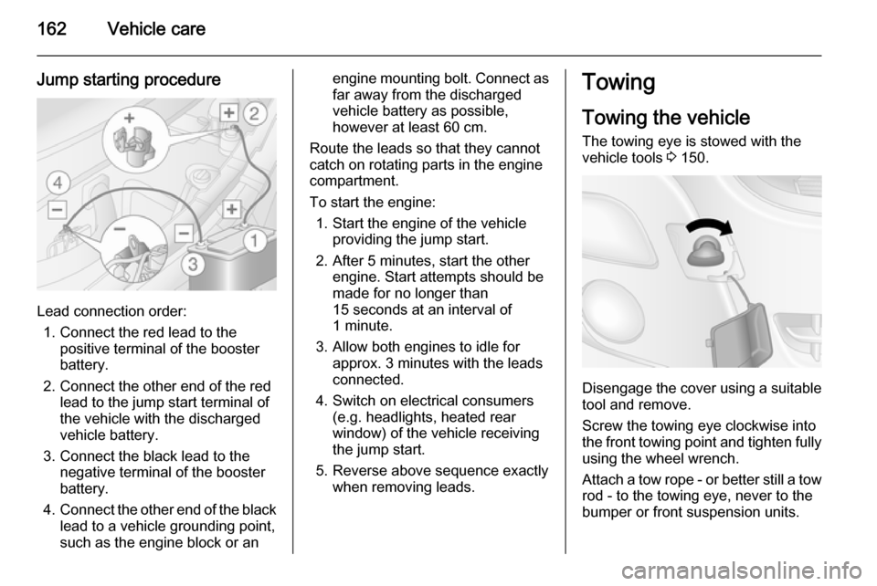
Jump starting procedure
Lead connection order:1. Connect the red lead to the positive terminal of the booster
battery.
2. Connect the other end of the red lead to the jump start terminal of
the vehicle with the discharged
vehicle battery.
3. Connect the black lead to the negative terminal of the booster
battery.
4. Connect the other end of the black
lead to a vehicle grounding point,
such as the engine block or an
engine mounting bolt. Connect as far away from the discharged
vehicle battery as possible,
however at least 60 cm.
Route the leads so that they cannot
catch on rotating parts in the engine
compartment.
To start the engine: 1. Start the engine of the vehicle providing the jump start.
2. After 5 minutes, start the other engine. Start attempts should be
made for no longer than
15 seconds at an interval of
1 minute.
3. Allow both engines to idle for approx. 3 minutes with the leads
connected.
4. Switch on electrical consumers (e.g. headlights, heated rear
window) of the vehicle receiving
the jump start.
5. Reverse above sequence exactly when removing leads.Towing
Towing the vehicle The towing eye is stowed with thevehicle tools 3 150.
Disengage the cover using a suitable
tool and remove.
Screw the towing eye clockwise into
the front towing point and tighten fully using the wheel wrench.
Attach a tow rope - or better still a tow
rod - to the towing eye, never to the
bumper or front suspension units.