2014 VAUXHALL MOVANO_B jump start
[x] Cancel search: jump startPage 113 of 201
Driving and operating111
Master switchCaution
The air suspension system must
be switched off when the vehicle is being towed, jump‐started, raised
off the ground or transported.
Do not switch off the air
suspension system when driving.
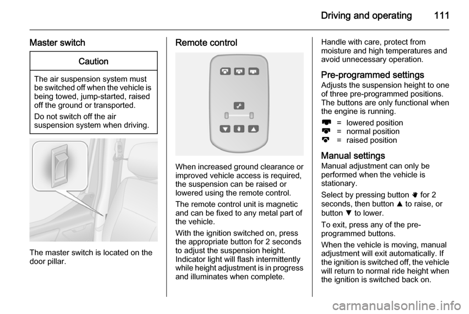
The master switch is located on the
door pillar.
Remote control
When increased ground clearance or
improved vehicle access is required,the suspension can be raised or
lowered using the remote control.
The remote control unit is magnetic
and can be fixed to any metal part of
the vehicle.
With the ignition switched on, press
the appropriate button for 2 seconds
to adjust the suspension height.
Indicator light will flash intermittently
while height adjustment is in progress
and illuminates when complete.
Handle with care, protect from
moisture and high temperatures and
avoid unnecessary operation.
Pre-programmed settings Adjusts the suspension height to oneof three pre-programmed positions.
The buttons are only functional when
the engine is running.l=lowered positionk=normal positionj=raised position
Manual settings
Manual adjustment can only be
performed when the vehicle is
stationary.
Select by pressing button h for 2
seconds, then button R to raise, or
button S to lower.
To exit, press any of the pre-
programmed buttons.
When the vehicle is moving, manual
adjustment will exit automatically. If
the ignition is switched off, the vehicle
will return to normal ride height when
the ignition is switched back on.
Page 119 of 201
Driving and operating117
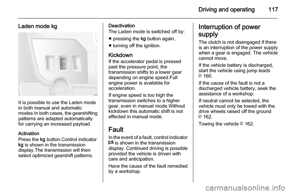
Laden mode kg
It is possible to use the Laden mode
in both manual and automatic
modes.In both cases, the gearshifting
patterns are adapted automatically
for carrying an increased payload.
Activation
Press the kg button.Control indicator
kg is shown in the transmission
display.The transmission will then
select optimized gearshift patterns.
Deactivation
The Laden mode is switched off by:
■ pressing the kg button again,
■ turning off the ignition.
Kickdown If the accelerator pedal is pressedpast the pressure point, the
transmission shifts to a lower gear
depending on engine speed.Full
engine power is available for
acceleration.
If engine speed is too high the
transmission switches to a higher
gear, even in manual mode.Without
kickdown this automatic shift is not
effected in manual mode.
Fault In the event of a fault, control indicator
W is shown in the transmission
display. Continued driving is possible
provided the vehicle is driven with
care and anticipation.
Have the cause of the fault remedied
by a workshop.Interruption of power
supply The clutch is not disengaged if there
is an interruption of the power supply
when a gear is engaged. The vehicle
cannot move.
If the vehicle battery is discharged,
start the vehicle using jump leads
3 160.
If the cause of the fault is not a discharged vehicle battery, seek the
assistance of a workshop.
If neutral cannot be selected, the
vehicle must only be towed with the drive wheels raised off the ground
3 162.
Towing the vehicle 3 162.
Page 134 of 201

132Vehicle careVehicle careGeneral Information...................132
Vehicle checks ........................... 133
Bulb replacement .......................140
Electrical system ........................148
Vehicle tools .............................. 150
Wheels and tyres .......................151
Jump starting ............................. 160
Towing ....................................... 162
Appearance care .......................164General Information
Accessories and vehicle
modifications
We recommend the use of genuine parts and accessories and factory
approved parts specific for your
vehicle type. We cannot assess or
guarantee reliability of other products
- even if they have a regulatory or
otherwise granted approval.
Do not make any modifications to the electrical system, e.g. changes of
electronic control units (chip tuning).
Vehicle storage Storage for a long period of time
The following tasks must be carried
out if the vehicle is to be stored for several months:
■ Wash and wax the vehicle.
■ Have the wax in the engine compartment and underbody
checked.
■ Clean and preserve rubber seals.■ Change engine oil.
■ Drain washer fluid reservoir.
■ Check coolant antifreeze.
■ Adjust tyre pressure to the value specified for full load.
■ Park vehicle in a dry, well ventilated
place.Engage first or reverse
gear.Prevent the vehicle from
rolling.
■ Do not apply parking brake.
■ Open bonnet, close all doors and lock the vehicle.
■ Disconnect the clamp from the negative terminal of the vehicle
battery.Beware that all systems are
not functional, e.g. anti-theft alarm
system.
Putting back into operation
The following tasks must be carried
out if the vehicle is being put back into operation:
■ Connect the clamp to the negative terminal of the vehicle
battery.Activate the electronics of
the power windows.
■ Check tyre pressure.
Page 157 of 201
Vehicle care155
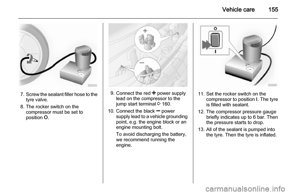
7.Screw the sealant filler hose to the
tyre valve.
8. The rocker switch on the compressor must be set to
position O.9.
Connect the red < power supply
lead on the compressor to the
jump start terminal 3 160.
10. Connect the black ] power
supply lead to a vehicle grounding
point, e.g. the engine block or an
engine mounting bolt.
To avoid discharging the battery,
we recommend running the
engine.11. Set the rocker switch on the compressor to position I. The tyre
is filled with sealant.
12. The compressor pressure gauge briefly indicates up to 6 bar. Then
the pressure starts to drop.
13. All of the sealant is pumped into the tyre. Then the tyre is inflated.
Page 162 of 201
160Vehicle care
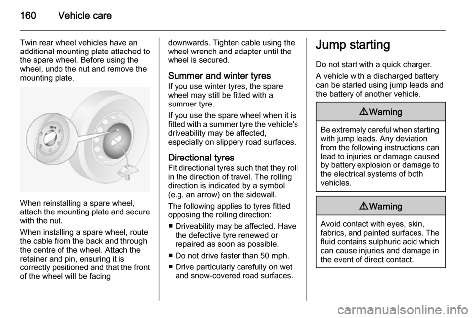
Twin rear wheel vehicles have an
additional mounting plate attached to
the spare wheel. Before using the
wheel, undo the nut and remove the
mounting plate.
When reinstalling a spare wheel,
attach the mounting plate and secure with the nut.
When installing a spare wheel, route
the cable from the back and through
the centre of the wheel. Attach the
retainer and pin, ensuring it is
correctly positioned and that the front
of the wheel will be facing
downwards. Tighten cable using the
wheel wrench and adapter until the wheel is secured.
Summer and winter tyres If you use winter tyres, the spare
wheel may still be fitted with a
summer tyre.
If you use the spare wheel when it is
fitted with a summer tyre the vehicle's driveability may be affected,
especially on slippery road surfaces.
Directional tyres Fit directional tyres such that they rollin the direction of travel. The rolling
direction is indicated by a symbol
(e.g. an arrow) on the sidewall.
The following applies to tyres fitted
opposing the rolling direction:
■ Driveability may be affected. Have the defective tyre renewed or
repaired as soon as possible.
■ Do not drive faster than 50 mph.
■ Drive particularly carefully on wet and snow-covered road surfaces.Jump starting
Do not start with a quick charger.
A vehicle with a discharged battery
can be started using jump leads and
the battery of another vehicle.9 Warning
Be extremely careful when starting
with jump leads. Any deviation
from the following instructions can
lead to injuries or damage caused
by battery explosion or damage to the electrical systems of both
vehicles.
9 Warning
Avoid contact with eyes, skin,
fabrics, and painted surfaces. The fluid contains sulphuric acid which can cause injuries and damage in
the event of direct contact.
Page 163 of 201
Vehicle care161Caution
The air suspension system must
be switched off prior to jump
starting.
9 Warning
Avoid contact of the battery with
eyes, skin, fabrics and painted
surfaces. The fluid contains
sulphuric acid which can cause
injuries and damage in the event
of direct contact.
■ Never expose the vehicle battery to
naked flames or sparks.
■ A discharged vehicle battery can already freeze at a temperature of
0 °C. Defrost the frozen vehicle
battery before connecting jump
leads.
■ Wear eye protection and protective
clothing when handling a vehicle
battery.
■ Use a booster battery with the same voltage (12 volts). Its capacity(Ah) must not be much less than
that of the discharged vehicle
battery.
■ Use jump leads with insulated terminals and a cross section of at
least 25 mm 2
.
■ Do not disconnect the discharged battery from the vehicle.
■ Switch off all unnecessary electrical
consumers.
■ Switch off the air suspension system.
■ Do not lean over the vehicle battery
during jump starting.
■ Do not allow the terminals of one lead to touch those of the other
lead.
■ The vehicles must not come into contact with each other during the
jump starting process.
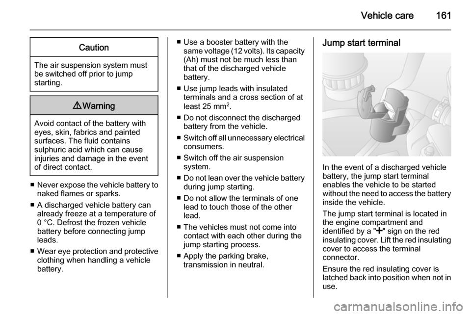
■ Apply the parking brake, transmission in neutral.Jump start terminal
In the event of a discharged vehicle
battery, the jump start terminal
enables the vehicle to be started
without the need to access the battery inside the vehicle.
The jump start terminal is located in
the engine compartment and
identified by a " <" sign on the red
insulating cover. Lift the red insulating
cover to access the terminal
connector.
Ensure the red insulating cover is
latched back into position when not in
use.
Page 164 of 201
162Vehicle care
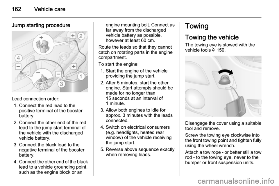
Jump starting procedure
Lead connection order:1. Connect the red lead to the positive terminal of the booster
battery.
2. Connect the other end of the red lead to the jump start terminal of
the vehicle with the discharged
vehicle battery.
3. Connect the black lead to the negative terminal of the booster
battery.
4. Connect the other end of the black
lead to a vehicle grounding point,
such as the engine block or an
engine mounting bolt. Connect as far away from the discharged
vehicle battery as possible,
however at least 60 cm.
Route the leads so that they cannot
catch on rotating parts in the engine
compartment.
To start the engine: 1. Start the engine of the vehicle providing the jump start.
2. After 5 minutes, start the other engine. Start attempts should be
made for no longer than
15 seconds at an interval of
1 minute.
3. Allow both engines to idle for approx. 3 minutes with the leads
connected.
4. Switch on electrical consumers (e.g. headlights, heated rear
window) of the vehicle receiving
the jump start.
5. Reverse above sequence exactly when removing leads.Towing
Towing the vehicle The towing eye is stowed with thevehicle tools 3 150.
Disengage the cover using a suitable
tool and remove.
Screw the towing eye clockwise into
the front towing point and tighten fully using the wheel wrench.
Attach a tow rope - or better still a tow
rod - to the towing eye, never to the
bumper or front suspension units.
Page 196 of 201

194IndexAAccessories and vehicle modifications .......................... 132
Adaptive forward lighting .....89, 142
Adjustable air vents ...................103
Airbag and belt tensioners ...........78
Airbag deactivation ................50, 78
Airbag label................................... 45 Airbag system .............................. 45
Air conditioning regular operation ................................ 105
Air conditioning system ................ 95
Air intake .................................... 104
Air suspension ........................... 110
Air vents...................................... 103
Antifreeze ................................... 135
Antilock brake system ................ 118
Antilock brake system (ABS) .......80
Anti-theft alarm system ................27
Anti-theft locking system .............. 27
Appearance care ........................164
Armrest ........................................ 40
Ashtrays ....................................... 72 Automatic light control .................87
Automatic locking ........................23
Auxiliary heater ........................... 100B
Battery, jump starting.................. 160
Belts.............................................. 43 Bonnet ....................................... 133
Brake assist ............................... 119
Brake fluid .......................... 136, 168
Brake pad wear ............................ 80
Brakes ............................... 118, 136
Brake system ............................... 79
Breakdown.................................. 162
Bulb replacement ....................... 140
C
Capacities .................................. 188
Cargo management system ........63
Car Pass ...................................... 18
Catalytic converter .....................112
Central locking system ................19
Centre high-mounted brake light 145
Changing tyre and wheel size ...153
Charging system .......................... 78
Child locks ................................... 23
Child restraint installation locations ................................... 53
Child restraints.............................. 51
Child restraint systems ................51
Cigarette lighter ........................... 72
Cleaning the vehicle ...................164
Climate control ............................. 14