Page 324 of 414
&When checking or servicing
in the engine compartment
while the engine is running
WARNING
A running engine can be dangerous.
Keep your fingers, hands, clothing,
hair and tools away from the cooling
fan, belts and any other moving
engine parts. Removing rings,
watches and ties is advisable. Engine hood
WARNING
Always check that the hood is
properly locked before you start
driving. If it is not, it might fly open
while the vehicle is moving and
block your view, which may cause
an accident and serious bodily in-
jury.
To open the hood:
1. If the wiper blades are lifted off the
windshield, return them to their originalposition.
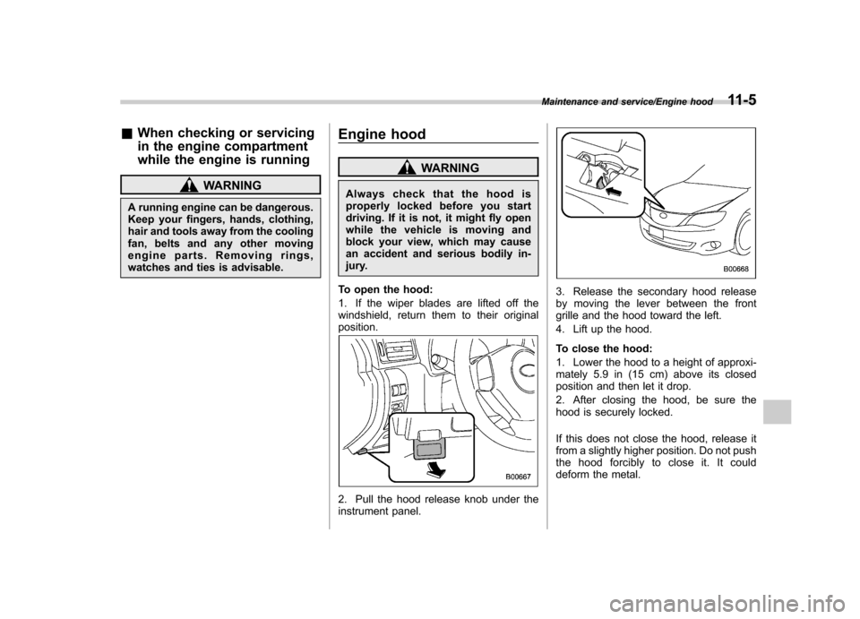
2. Pull the hood release knob under the
instrument panel.
3. Release the secondary hood release
by moving the lever between the front
grille and the hood toward the left.
4. Lift up the hood.
To close the hood:
1. Lower the hood to a height of approxi-
mately 5.9 in (15 cm) above its closed
position and then let it drop.
2. After closing the hood, be sure the
hood is securely locked.
If this does not close the hood, release it
from a slightly higher position. Do not push
thehoodforciblytocloseit.Itcould
deform the metal.
Maintenance and service/Engine hood11-5
Page 328 of 414
pipe, be sure to wipe it off.
. If the level gauge is not pulled out
easily, twist the level gauge right
and left, then pull it out. Other-
wise, you may be injured acci-
dentally straining yourself.
If you check the oil level just after stopping
the engine, wait a few minutes for the oil to
drain back into the oil pan before checking
the level.
Just after driving or while the engine is
warm, the engine oil level reading may be
in a range between the upper level and
the notch mark. This is caused by thermal
expansion of the engine oil.
To prevent overfilling the engine oil, do not
add any additional oil above the upper
level when the engine is cold. & Changing the oil and oil filter
CAUTION
. If you change your own oil, be
sure to drain all the oil from the
filter before disposal.
. Do not dispose of used engine oil
by placing it in the trash, or by
pouring it onto the ground, into
sewers, or into any body of water.
Check with your local govern- ment office for the proper dis-
posal options available to you.
Change the oil and oil filter according to
the maintenance schedule in the “War-
ranty and Maintenance Booklet ”.
The engine oil and oil filter must be
changed more frequently than listed in
the maintenance schedule when driving
on dusty roads, when short trips are
frequently made, or when driving in
extremely cold weather.
1. Warm up the engine by letting the
engine idle for approximately 10 minutes
to ease draining the engine oil.
2. Park the vehicle on a level surface and
stop the engine.
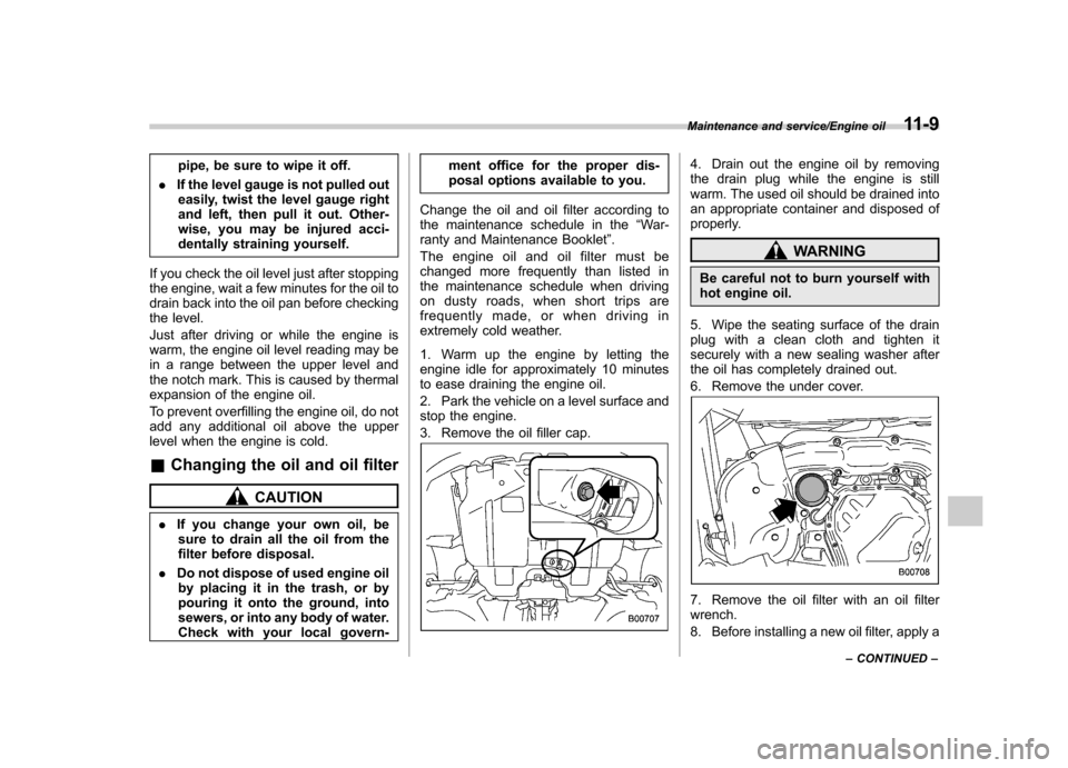
3. Remove the oil filler cap.
4. Drain out the engine oil by removing
the drain plug while the engine is still
warm. The used oil should be drained into
an appropriate container and disposed of
properly.
WARNING
Be careful not to burn yourself with
hot engine oil.
5. Wipe the seating surface of the drain
plug with a clean cloth and tighten it
securely with a new sealing washer after
the oil has completely drained out.
6. Remove the under cover.
7. Remove the oil filter with an oil filter wrench.
8. Before installing a new oil filter, apply a
Maintenance and service/Engine oil11-9
– CONTINUED –
Page 355 of 414
11-36Maintenance and service/Replacement of wiper blades
2. Pull the blade rubber assembly out of
the plastic support.
1) Metal spines
3. If the new blade rubber is not provided
with two metal spines, remove the metal
spines from the old blade rubber and
install them in the new blade rubber.
4. Align the claws of the plastic support
with the grooves in the blade rubber
assembly, then slide the blade rubber
assembly into place.
Securely retain both ends of the rubber
with the stoppers on the plastic support ends. If the rubber is not retained properly,
the wiper may scratch the rear windowglass.
5. Install the wiper blade assembly to the
wiper arm. Make sure that it locks in place.
6. Hold the wiper arm by hand and slowly
lower it in position.
Page 359 of 414
11-40Maintenance and service/Replacing bulbs
following precautions. .Do not replace any headlight
bulbs (both low beam and high
beam) by yourself.
. Do not remove/restore the head-
light assemblies by yourself.
. Do not remove any headlight-
assembly components by your-self.
For replacement, contact your
SUBARU dealer.
& Headlights (models without
HID headlights)
CAUTION
Halogen headlight bulbs become
very hot while in use. If you touch
the bulb surface with bare hands or
greasy gloves, fingerprints or
grease on the bulb surface will
develop into hot spots, causing the
bulb to break. If there are finger
prints or grease on the bulb surface,
wipe them away with a soft cloth
moistened with alcohol. NOTE .
If headlight aiming is required, con-
sult your SUBARU dealer for proper
adjustment of the headlight aim.. It may be difficult to replace the
bulbs. Have the bulbs replaced by your
SUBARU dealer if necessary. ! Low beam light bulbs
Right-hand side
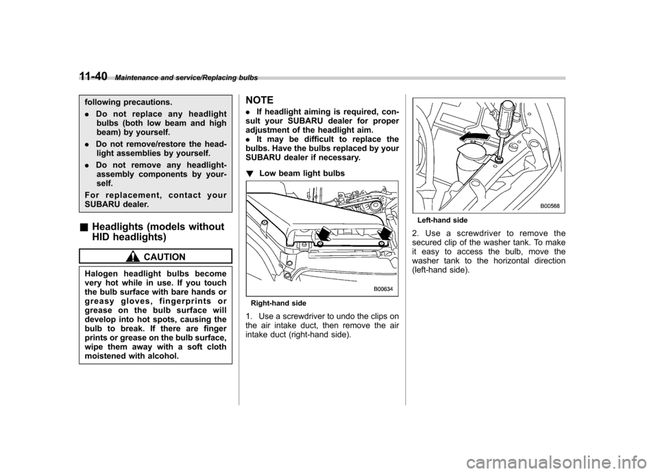
1. Use a screwdriver to undo the clips on
the air intake duct, then remove the air
intake duct (right-hand side).
Left-hand side
2. Use a screwdriver to remove the
secured clip of the washer tank. To make
it easy to access the bulb, move the
washer tank to the horizontal direction
(left-hand side).
Page 360 of 414
3. Remove the bulb cover, by turning it counterclockwise.
4. Disconnect the electrical connector
from the bulb.
5. Remove the bulb from the headlight
assembly by turning it counterclockwise.
6. Replace the bulb with a new one. At
this time, do not touch the bulb surface.
7. To install the bulb to the headlight
assembly, turn it clockwise until it clicks.
8. Reconnect the electrical connector.
9. Install the bulb cover.
10. Install the air intake duct with clips
(right-hand side).
11. Set the washer tank to the original
place and secure it by clip (left-hand side).!
High beam light bulbsRight-hand side
1. Use a screwdriver to undo the clips on
the air intake duct, then remove the air
intake duct (right-hand side).
Left-hand side
Maintenance and service/Replacing bulbs11-41
– CONTINUED –
Page 361 of 414
11-42Maintenance and service/Replacing bulbs
2. Use a screwdriver to remove the
secured clip of the washer tank. To make
it easy to access the bulb, move the
washer tank to the horizontal direction
(left-hand side).
3. Disconnect the electrical connector
from the bulb.
4. Remove the bulb from the headlight
assembly by turning it counterclockwise.
5. Replace the bulb with new one. At this
time, use care not to touch the bulbsurface.
6. To install the bulb to the headlight
assembly, turn it clockwise until it clicks.
7. Reconnect the electrical connector.
8. Install the air intake duct with clips
(right-hand side).
9. Set the washer tank to the original
place and secure it by clip (left-hand side).&
Front turn signal light
It may be difficult to replace the bulbs.
Have the bulbs replaced by your SUBARU
dealer if necessary. & Front fog light (if equipped)
NOTE
It may be difficult to replace the bulbs.
Have the bulbs replaced by your
SUBARU dealer if necessary.
Type A
Page 363 of 414
11-44Maintenance and service/Replacing bulbs
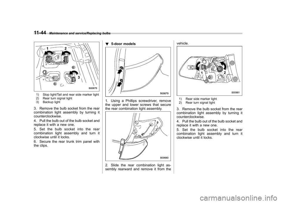
1) Stop light/Tail and rear side marker light
2) Rear turn signal light
3) Backup light
3. Remove the bulb socket from the rear
combination light assembly by turning itcounterclockwise.
4. Pull the bulb out of the bulb socket and
replace it with a new one.
5. Set the bulb socket into the rear
combination light assembly and turn it
clockwise until it locks.
6. Secure the rear trunk trim panel with
the clips. !
5-door models
1. Using a Phillips screwdriver, remove
the upper and lower screws that secure
the rear combination light assembly.
2. Slide the rear combination light as-
sembly rearward and remove it from the vehicle.
1) Rear side marker light
2) Rear turn signal light
3. Remove the bulb socket from the rear
combination light assembly by turning itcounterclockwise.
4. Pull the bulb out of the bulb socket and
replace it with a new one.
5. Set the bulb socket into the rear
combination light assembly and turn it
clockwise until it locks.
Page 393 of 414
13-8Consumer information and Reporting safety defects/Tire information
.Tread rib
A tread section running circumfer-
entially around a tire. . Tread separation
Pulling away of the tread from the
tire carcass. . Treadwear indicators (TWI)
The projections within the principal
grooves designed to give a visual
indication of the degrees of wear of
the tread. . Vehicle capacity weight
The rated cargo and luggage load
plus 150 lbs (68 kg) times thevehicle ’s designated seating capa-
city. . Vehicle maximum load on the
tire
Load on an individual tire that is
determined by distributing to each
axle its share of the maximum
loaded vehicle weight and dividing
by two. . Vehicle normal load on the tire
Load on an individual tire that is
determined by distributing to each
axle its share of the curb weight, accessory weight, and normal oc-
cupant weight (distributed in accor-
dance with Table 1 that is ap-
pended to the end of this section)
and dividing by 2.
. Wheel-holding fixture
The fixture used to hold the wheel
and tire assembly securely duringtesting.