2014 SUBARU IMPREZA WRX traction control
[x] Cancel search: traction controlPage 264 of 414
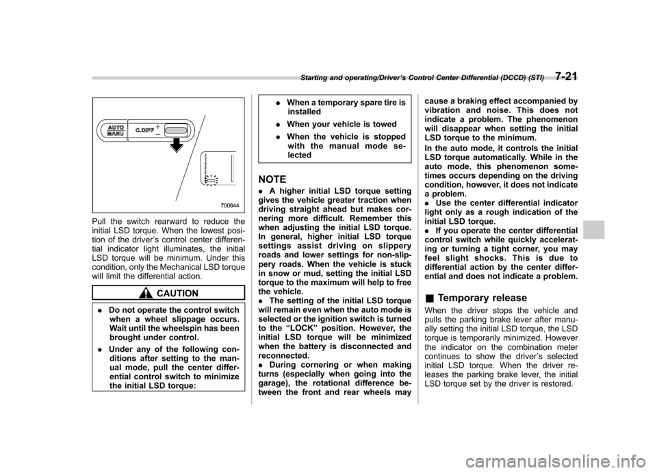
Pull the switch rearward to reduce the
initial LSD torque. When the lowest posi-
tion of the driver’s control center differen-
tial indicator light illuminates, the initial
LSD torque will be minimum. Under this
condition, only the Mechanical LSD torque
will limit the differential action.
CAUTION
. Do not operate the control switch
when a wheel slippage occurs.
Wait until the wheelspin has been
brought under control.
. Under any of the following con-
ditions after setting to the man-
ual mode, pull the center differ-
ential control switch to minimize
the initial LSD torque: .
When a temporary spare tire is
installed
. When your vehicle is towed
. When the vehicle is stopped
with the manual mode se-lected
NOTE . A higher initial LSD torque setting
gives the vehicle greater traction when
driving straight ahead but makes cor-
nering more difficult. Remember this
when adjusting the initial LSD torque.
In general, higher initial LSD torque
settings assist driving on slippery
roads and lower settings for non-slip-
pery roads. When the vehicle is stuck
in snow or mud, setting the initial LSD
torque to the maximum will help to free
the vehicle.. The setting of the initial LSD torque
will remain even when the auto mode is
selected or the ignition switch is turned
to the “LOCK ”position. However, the
initial LSD torque will be minimized
when the battery is disconnected andreconnected.. During cornering or when making
turns (especially when going into the
garage), the rotational difference be-
tween the front and rear wheels may cause a braking effect accompanied by
vibration and noise. This does not
indicate a problem. The phenomenon
will disappear when setting the initial
LSD torque to the minimum.
In the auto mode, it controls the initial
LSD torque automatically. While in the
auto mode, this phenomenon some-
times occurs depending on the driving
condition, however, it does not indicate
a problem..
Use the center differential indicator
light only as a rough indication of the
initial LSD torque.. If you operate the center differential
control switch while quickly accelerat-
ing or turning a tight corner, you may
feel slight shocks. This is due to
differential action by the center differ-
ential and does not indicate a problem. & Temporary release
When the driver stops the vehicle and
pulls the parking brake lever after manu-
ally setting the initial LSD torque, the LSD
torque is temporarily minimized. However
the indicator on the combination meter
continues to show the driver ’s selected
initial LSD torque. When the driver re-
leases the parking brake lever, the initial
LSD torque set by the driver is restored.
Starting and operating/Driver ’s Control Center Differential (DCCD) (STI)7-21
Page 272 of 414

of the Vehicle Dynamics Con-
trol system is reduced and
this should be taken into ac-
count when driving the vehi-
cle in such a condition.
. If non-matching tires are used,
the Vehicle Dynamics Control
system may not operate cor-
rectly.
. The Vehicle Dynamics Control
system helps prevent unstable
vehicle motion such as skidding
using control of the brakes and
engine power. Do not turn off the
Vehicle Dynamics Control sys-
tem unless it is absolutely ne-
cessary. If you must turn off the
Vehicle Dynamics Control sys-
tem, drive very carefully based
on the road surface condition.
In the event of wheelspin and/or skidding
on a slippery road surface and/or during
cornering and/or an evasive maneuver,
the Vehicle Dynamics Control system
adjusts the engine ’s output and the
wheels ’respective braking forces to help
maintain traction and directional control. . Traction Control Function
The traction control function is designed to
prevent spinning of the driving wheels on
slippery road surfaces, thereby helping to maintain traction and directional control.
Activation of this function is shown by
flashing the Vehicle Dynamics Control
operation indicator light. .
Skid Suppression Function
The skid suppression function is designed
to help maintain directional stability by
suppressing the wheels ’tendency to slide
sideways during steering operations. Acti-
vation of this function is shown by flashing
the Vehicle Dynamics Control operation
indicator light.
NOTE . The Vehicle Dynamics Control sys-
tem may be considered normal when
the following conditions occur.
–Slight twitching of the brake
pedal is felt. – The vehicle or steering wheel
shakes to a small degree.– An operating sound from the
engine compartment is heard
briefly when starting the engine
and when driving off after starting
the engine. – The brake pedal seems to jolt
when driving off after starting the engine.
. In the following circumstances, the
vehicle may be less stable than it feels to the driver. The Vehicle Dynamics
Control System may therefore operate.
Such operation does not indicate a
system malfunction.
–on gravel-covered or rutted
roads – on unfinished roads
– when the vehicle is fitted with
snow tires or winter tires
. Activation of the Vehicle Dynamics
Control system will cause operation of
the steering wheel to feel slightly
different compared to that for normalconditions. . It is always important to reduce
speed when approaching a corner,
even if the vehicle is equipped with
Vehicle Dynamics Control. . Always turn off the engine before
replacing a tire as failure to do so may
render the Vehicle Dynamics Control
system unable to operate correctly. & Vehicle Dynamics Control
system monitor
Refer to “Vehicle Dynamics Control warn-
ing light/Vehicle Dynamics Control opera-
tion indicator light ”F 3-20 and “Vehicle
Dynamics Control OFF indicator light/
Traction Control OFF indicator light (STI) ”
F 3-21.
Starting and operating/Vehicle Dynamics Control system7-29
– CONTINUED –
Page 273 of 414
7-30Starting and operating/Vehicle Dynamics Control system
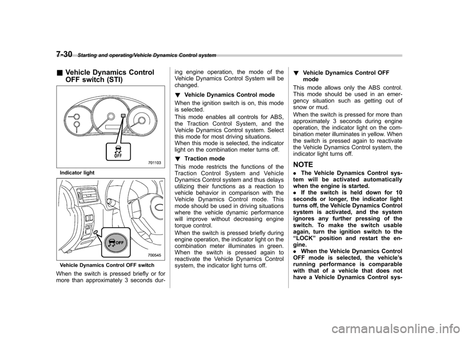
&Vehicle Dynamics Control
OFF switch (STI)
Indicator light
Vehicle Dynamics Control OFF switch
When the switch is pressed briefly or for
more than approximately 3 seconds dur- ing engine operation, the mode of the
Vehicle Dynamics Control System will bechanged. !
Vehicle Dynamics Control mode
When the ignition switch is on, this mode
is selected.
This mode enables all controls for ABS,
the Traction Control System, and the
Vehicle Dynamics Control system. Select
this mode for most driving situations.
When this mode is selected, the indicator
light on the combination meter turns off. ! Traction mode
This mode restricts the functions of the
Traction Control System and Vehicle
Dynamics Control system and thus delays
utilizing their functions as a reaction to
vehicle behavior in comparison with the
Vehicle Dynamics Control mode. This
mode should be used in driving situations
where the vehicle dynamic performance
will improve without decreasing engine
torque control.
When the switch is pressed briefly during
engine operation, the indicator light on the
combination meter illuminates in green.
When the switch is pressed again to
reactivate the Vehicle Dynamics Control
system, the indicator light turns off. !
Vehicle Dynamics Control OFFmode
This mode allows only the ABS control.
This mode should be used in an emer-
gency situation such as getting out of
snow or mud.
When the switch is pressed for more than
approximately 3 seconds during engine
operation, the indicator light on the com-
bination meter illuminates in yellow. When
the switch is pressed again to reactivate
the Vehicle Dynamics Control system, the
indicator light turns off.
NOTE . The Vehicle Dynamics Control sys-
tem will be activated automatically
when the engine is started.. If the switch is held down for 10
seconds or longer, the indicator light
turns off, the Vehicle Dynamics Control
system is activated, and the system
ignores any further pressing of the
switch. To make the switch usable
again, turn the ignition switch to the“ LOCK ”position and restart the en-
gine.. When the Vehicle Dynamics Control
OFF mode is selected, the vehicle ’s
running performance is comparable
with that of a vehicle that does not
have a Vehicle Dynamics Control sys-
Page 274 of 414
tem. Do not deactivate the Vehicle
Dynamics Control system except when
absolutely necessary..Even when the Vehicle Dynamics
Control OFF mode is selected, compo-
nents of the brake control system may
still activate. When the brake control
system is activated, the Vehicle Dy-
namics Control operation indicator
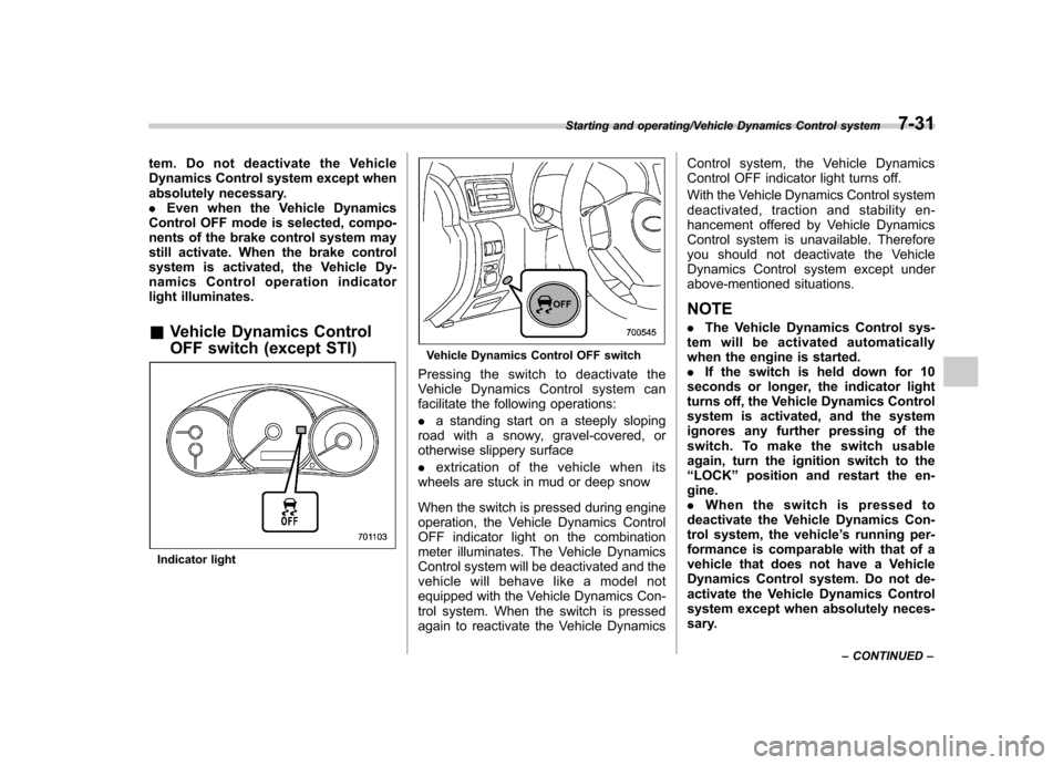
light illuminates. & Vehicle Dynamics Control
OFF switch (except STI)
Indicator light
Vehicle Dynamics Control OFF switch
Pressing the switch to deactivate the
Vehicle Dynamics Control system can
facilitate the following operations: . a standing start on a steeply sloping
road with a snowy, gravel-covered, or
otherwise slippery surface . extrication of the vehicle when its
wheels are stuck in mud or deep snow
When the switch is pressed during engine
operation, the Vehicle Dynamics Control
OFF indicator light on the combination
meter illuminates. The Vehicle Dynamics
Control system will be deactivated and the
vehicle will behave like a model not
equipped with the Vehicle Dynamics Con-
trol system. When the switch is pressed
again to reactivate the Vehicle Dynamics Control system, the Vehicle Dynamics
Control OFF indicator light turns off.
With the Vehicle Dynamics Control system
deactivated, traction and stability en-
hancement offered by Vehicle Dynamics
Control system is unavailable. Therefore
you should not deactivate the Vehicle
Dynamics Control system except under
above-mentioned situations. NOTE .
The Vehicle Dynamics Control sys-
tem will be activated automatically
when the engine is started.. If the switch is held down for 10
seconds or longer, the indicator light
turns off, the Vehicle Dynamics Control
system is activated, and the system
ignores any further pressing of the
switch. To make the switch usable
again, turn the ignition switch to the“ LOCK ”position and restart the en-
gine.. Whentheswitchispressedto
deactivate the Vehicle Dynamics Con-
trol system, the vehicle ’s running per-
formance is comparable with that of a
vehicle that does not have a Vehicle
Dynamics Control system. Do not de-
activate the Vehicle Dynamics Control
system except when absolutely neces-
sary.
Starting and operating/Vehicle Dynamics Control system7-31
– CONTINUED –
Page 288 of 414

printed on the tire placard. The
tire placard is located on the
bottom of driver’s door pillar.
If all of four tires are not the same
for items (a) to (h), there is a
possibility that serious mechan-
ical damage could occur to the
drive train of your car, and affect
the following. — Ride
— Handling
— Braking
— Speedometer/Odometer
calibration— Clearance between the body
and tires
It also may be dangerous and
lead to loss of vehicle control,
and it can lead to an accident.
CAUTION
If you use a temporary spare tire to
replace a flat tire, be sure to use the
original temporary spare tire stored
in the vehicle. Using other sizes may
result in severe mechanical damage
to the drive train of your vehicle.
All-Wheel Drive distributes the engine
power to all four wheels. AWD models
provide better traction when driving on
slippery, wet or snow-covered roads and
when moving out of mud, dirt and sand.
By shifting power between the front and
rear wheels, SUBARU AWD can also
provide added traction during acceleration
and added engine braking force duringdeceleration.
Therefore, your SUBARU AWD vehicle
may handle differently than an ordinary
two wheel drive vehicle and it contains
some features unique to AWD. For safety
purposes as well as to avoid damaging
the AWD system, you should keep the
following tips in mind. . An AWD model is better able to climb
steeper roads under snowy or slippery conditions than a two wheel drive vehicle.
There is little difference in handling,
however, during extremely sharp turns or
sudden braking. Therefore, when driving
down a slope or turning corners, be sure
to reduce your speed and maintain an
ample distance from other vehicles. .
Always check the cold tire pressure
before starting to drive. The recom-
mended tire pressure is provided on the
tire placard, which is located under the
door latch on the driver ’s side.
. Frequent driving of an AWD model
under hard-driving conditions such as
steep hills or dusty roads will necessitate
more frequent replacement of the follow-
ing items than that specified in “Mainte-
nance schedule ”F 11-3.
– Engine oil
– Brake fluid
– Rear differential gear oil
– Manual transmission oil
. There are some precautions that you
must observe when towing your vehicle.
For detailed information, refer to “Towing ”
F 9-12.
Driving tips/Driving tips for AWD models8-5
Page 292 of 414
obey the specification that is
printed on the tire placard. The
tire placard is located on the
bottom of driver’s door pillar.
If all of four winter tires are not
the same for items (a) to (h), there
is a possibility that serious me-
chanical damage could occur to
the drive train of your car, and
affect the following. — Ride
— Handling
— Braking
— Speedometer/Odometer
calibration— Clearance between the body
and tires
It also may be dangerous and
lead to loss of vehicle control,
and it can lead to an accident.
. Do not use a combination of
radial, belted bias or bias tires
since it may cause dangerous
handling characteristics and lead
to an accident.
Your vehicle is equipped with “summer
tires ”as original equipment, which are
inadequate for driving on slippery roads
such as on snow-covered or icy roads. Compared with winter and all-season
tires, summer tires give significantly less
grip on snowy and icy road surfaces.
Therefore, use of winter tires is strongly
recommended when driving with such
road conditions.
When you choose to install winter tires on
your vehicle, be sure to use the correct tire
size and type. You must install four winter
tires that are of the same size, construc-
tion, brand and load range and you should
never mix radial, belted bias or bias tires
since this may result in dangerous hand-
ling characteristics. When you choose a
tire, make sure that there is enough
clearance between the tire and vehicle
body.
Remember to drive with care at all times
regardless of the type of tires on yourvehicle.
& Tire chains
CAUTION
Tire chains cannot be used on your
Impreza, WRX and STI because of
the lack of clearance between the
tires and vehicle body. &
Rocking the vehicle
If you must rock the vehicle to free it from
snow, sand, or mud, depress the accel-
erator pedal slightly and move the shift
lever back and forth between “1 ” and “R ”
repeatedly. Do not race the engine. For
the best possible traction, avoid spinning
the wheels when trying to free the vehicle.
When the road surface is extremely
slippery, you can obtain better traction by
starting the vehicle with the transmission
in 2nd than 1st.
Driving tips/Winter driving8-9
Page 400 of 414
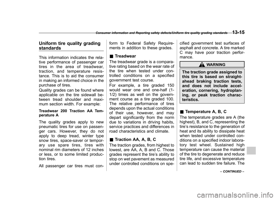
Uniform tire quality grading standards
This information indicates the rela-
tive performance of passenger car
tires in the area of treadwear,
traction, and temperature resis-
tance. This is to aid the consumer
in making an informed choice in the
purchase of tires.
Quality grades can be found where
applicable on the tire sidewall be-
tween tread shoulder and maxi-
mum section width. For example:
Treadwear 200 Traction AA Tem-
perature A
The quality grades apply to new
pneumatic tires for use on passen-
ger cars. However, they do not
apply to deep tread, winter type
snow tires, space-saver or tempor-
ary use spare tires, tires with
nominal rim diameters of 12 inches
or less, or to some limited produc-
tion tires.
All passenger car tires must con-form to Federal Safety Require-
ments in addition to these grades.
& Treadwear
The treadwear grade is a compara-
tive rating based on the wear rate of
the tire when tested under con-
trolled conditions on a specified
government test course.
For example, a tire graded 150
would wear one and one-half (1-
1/2) times as well on the govern-
ment course as a tire graded 100.
The relative performance of tires
depends upon the actual conditions
of their use, however, and may
depart significantly from the norm
due to variations in driving habits,
service practices and differences in
road characteristics and climate. & Traction AA, A, B, C
The traction grades, from highest to
lowest, are AA, A, B and C. Those
grades represent the tire ’s ability to
stop on wet pavement as measured
under controlled conditions on spe- cified government test surfaces of
asphalt and concrete. A tire marked
C may have poor traction perfor- mance.
WARNING
The traction grade assigned to
this tire is based on straight-
ahead braking traction tests,
and does not include accel-
eration, cornering, hydroplan-
ing, or peak traction charac-teristics.
& Temperature A, B, C
The temperature grades are A (the
highest), B, and C, representing thetire ’s resistance to the generation of
heat and its ability to dissipate heat
when tested under controlled con-
ditions on a specified indoor labora-
tory test wheel. Sustained high
temperature can cause the material
of the tire to degenerate and reduce
tire life, and excessive temperature
can lead to sudden tire failure. The
Consumer information and Reporting safety defects/Uniform tire quality grading standards13-15
– CONTINUED –
Page 407 of 414

14-6Index
I
Ignition switch .............................................................. 3-3
Light ....................................................................... 3-4
Illumination brightness control ...................................... 3-31
Immobilizer. ................................................................. 2-2
Indicator light (security indicator light) ....................... 3-23
Indicator light Cruise control ........................................................ 3-24
Cruise control set ................................................... 3-24
Front fog light ........................................................ 3-24
Headlight .............................................................. 3-24
High beam ............................................................ 3-24
Hill start assist OFF ................................................ 3-20
Immobilizer. ........................................................... 3-23
REV ..................................................................... 3-25Security ................................................................ 3-23
Shift-up ................................................................. 3-23
SI-DRIVE .............................................................. 3-23
Traction control OFF ............................................... 3-21
Turn signal ............................................................ 3-24
Vehicle Dynamics Control OFF ................................ 3-21
Vehicle Dynamics Control operation ................. 3-20, 3-21
Information display ..................................................... 3-26
Inside mirror .............................................................. 3-38
Interior lights ............................................................... 6-2
Internal trunk lid release handle ................................... 2-24
iPod
®operations ........................................................ 5-26
J
Jack and jack handle .................................................... 9-4
Jack-up point ............................................................... 9-5 Jump starting
.............................................................. 9-9
K
Key............................................................................ 2-2 Number .................................................................. 2-2
Reminder chime ...................................................... 3-4
Replacement. .......................................................... 2-3
L
Leather seat materials ................................................. 10-5
License plate light ..................................................... 11-46
Light Backup (4-door) ................................................... 11-43
Backup (5-door) ................................................... 11-45
Cargo area .................................................... 6-2, 11-47
Control switch ........................................................ 3-29
Daytime running ..................................................... 3-30
Dome ............................................................ 6-2, 11-47
Front fog ..................................................... 3-34, 11-42
Front position ......................................................... 3-29
Front side marker ................................................. 12-14
High-mounted stop ............................................... 11-48
Ignition switch ......................................................... 3-4
License plate ....................................................... 11-46
Map .............................................................. 6-3, 11-46
Rear combination ................................................. 11-43
Rear side marker light ........................................... 11-43
Stop light ............................................................. 11-43
Tail light. .............................................................. 11-43
Trunk .................................................................. 11-47
Turn signal ........................................ 3-31, 11-42, 11-43