2014 SUBARU IMPREZA WRX oil
[x] Cancel search: oilPage 177 of 414
4-12Climate control/Operating tips for heater and air conditioner
properly and become damaged, the sys-
tem may not be able to control the interior
temperature correctly. To avoid damaging
the sensors, observe the following pre-cautions. –Do not subject the sensors to impact.
– Keep water away from the sensors.
– Do not cover the sensors.
The sensors are located as follows.– Solar sensor: beside the windshield
defroster grille.– Interior air temperature sensor: near
the ignition switch.– Outside temperature sensor: behind
the front grille. Operating tips for heater and
air conditioner &
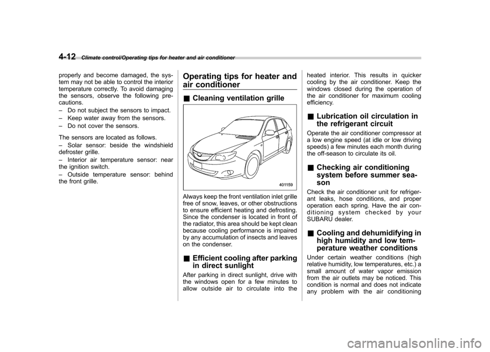
Cleaning ventilation grille
Always keep the front ventilation inlet grille
free of snow, leaves, or other obstructions
to ensure efficient heating and defrosting.
Since the condenser is located in front of
the radiator, this area should be kept clean
because cooling performance is impaired
by any accumulation of insects and leaves
on the condenser. &Efficient cooling after parking
in direct sunlight
After parking in direct sunlight, drive with
the windows open for a few minutes to
allow outside air to circulate into the heated interior. This results in quicker
cooling by the air conditioner. Keep the
windows closed during the operation of
the air conditioner for maximum cooling
efficiency. &
Lubrication oil circulation in
the refrigerant circuit
Operate the air conditioner compressor at
a low engine speed (at idle or low driving
speeds) a few minutes each month during
the off-season to circulate its oil. & Checking air conditioning
system before summer sea-son
Check the air conditioner unit for refriger-
ant leaks, hose conditions, and proper
operation each spring. Have the air con-
ditioning system checked by your
SUBARU dealer. & Cooling and dehumidifying in
high humidity and low tem-
perature weather conditions
Under certain weather conditions (high
relative humidity, low temperatures, etc.) a
small amount of water vapor emission
from the air outlets may be noticed. This
condition is normal and does not indicate
any problem with the air conditioning
Page 222 of 414
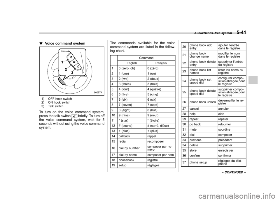
!Voice command system
1) OFF hook switch
2) ON hook switch
3) Talk switch
To turn on the voice command system,
press the talk switch
briefly. To turn off
the voice command system, wait for 5
seconds without using the voice commandsystem. The commands available for the voice
command system are listed in the follow-
ing chart.
Command
English Français
1 0 (zero, oh) 0 (zéro)
2 1 (one) 1 (un)
3 2 (two) 2 (deux)
4 3 (three) 3 (trois)
5 4 (four) 4 (quatre)
6 5 (five) 5 (cinq)
7 6 (six) 6 (six)
8 7 (seven) 7 (sept)
9 8 (eight) 8 (huit)
10 9 (nine) 9 (neuf)
11 * (star) * (étoile)
12 # (pound) # (carré, dièse)
13 + (plus) + (plus)
14 callback rappel
15 redial recomposer
16 dial by number composer par nu- méro
17 dial by name composer par nom
18 phonebook registre
19 setup réglages 20
phone book add entry ajouter l
’entrée
dans le registre
21 phone book
change name modifier le nom
dans le registre
22 phone book deleteentry supprimer l
’entrée
du registre
23 phone book listnames lister les noms duregistre
24 phone book set
speed dial configurer compo-
sition abrégée pour
le registre
25 phone book delete
speed dial supprimer compo-
sition abrégée pour
le registre
26 phone book unlock déverrouiller le re-gistre
27 cancel annuler
28 help aide
29 repeat répéter
30 go back retourner
31 mute sourdine
32 dial composer
33 previous précédent
34 delete supprimer
35 store enregistrer
36 confirm confirmer
37 phone setup réglages du télé- phone
Audio/Hands
–free system5-41
– CONTINUED –
Page 237 of 414
6-8Interior equipment/Accessory power outlets
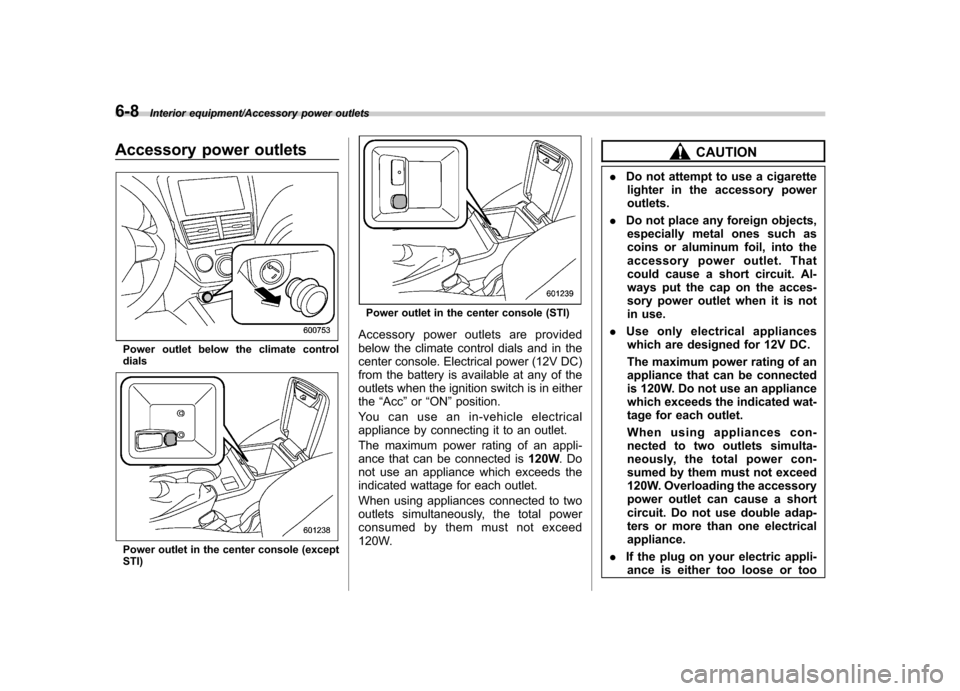
Accessory power outlets
Power outlet below the climate control dials
Power outlet in the center console (except STI)
Power outlet in the center console (STI)
Accessory power outlets are provided
below the climate control dials and in the
center console. Electrical power (12V DC)
from the battery is available at any of the
outlets when the ignition switch is in eitherthe “Acc ”or “ON ”position.
You can use an in-vehicle electrical
appliance by connecting it to an outlet.
The maximum power rating of an appli-
ance that can be connected is 120W.Do
not use an appliance which exceeds the
indicated wattage for each outlet.
When using appliances connected to two
outlets simultaneously, the total power
consumed by them must not exceed
120W.
CAUTION
. Do not attempt to use a cigarette
lighter in the accessory power outlets.
. Do not place any foreign objects,
especially metal ones such as
coins or aluminum foil, into the
accessory power outlet. That
could cause a short circuit. Al-
ways put the cap on the acces-
sory power outlet when it is not
in use.
. Use only electrical appliances
which are designed for 12V DC.
The maximum power rating of an
appliance that can be connected
is 120W. Do not use an appliance
which exceeds the indicated wat-
tage for each outlet.
When using appliances con-
nected to two outlets simulta-
neously, the total power con-
sumed by them must not exceed
120W. Overloading the accessory
power outlet can cause a short
circuit. Do not use double adap-
ters or more than one electricalappliance.
. If the plug on your electric appli-
ance is either too loose or too
Page 251 of 414

7-8Starting and operating/Preparing to drive
.A vehiclefails the OBDII inspection if
the “CHECK ENGINE ”warning light is not
properly operating (light is illuminated or is
not working due to a burned out bulb) or
there is one or more diagnostic trouble
codes stored in the vehicle ’s computer.
. A state emission inspection may reject
(not pass or fail) a vehicle if the number of
OBDII system readiness monitors “NOT
READY ”is greater than one. If the
vehicle ’s battery has been recently re-
placed or disconnected, the OBDII system
inspection may indicate that the vehicle is
not ready for the emission test. Under this
condition, the vehicle driver should be
instructed to drive his/her vehicle for a few
days to reset the readiness monitors and
return for an emission re-inspection. . Owners of rejected or failing vehicles
should contact their SUBARU Dealer for service.
Some states still use dynamometers in
their emission inspection program. A
dynamometer is a treadmill or roller-like
testing device that allows your vehicle ’s
wheels to turn while the vehicle remains in
one place. Prior to your vehicle being put
on a dynamometer, tell your emission
inspector
not to place your SUBARU
AWD vehicle on a two-wheel dynam-
ometer. Otherwise, serious transmis-
sion damage will result. The U.S. Environmental Protection
Agency (EPA) and states using two-wheel
dynamometers in their emission testing
program have EXEMPTED SUBARU
AWD vehicles from the portion of the
testing program that involves a two-wheel
dynamometer. There are some states that
use four-wheel dynamometers in their
testing program. When properly used, this
equipment should not damage a SUBARU
AWD vehicle.
Under no circumstances should the rear
wheels be jacked off the ground, nor
should the driveshaft be disconnected for
state emission testing.
Preparing to drive
You should perform the following checks
and adjustments every day before you
start driving.
1. Check that all windows, mirrors, and
lights are clean and unobstructed.
2. Check the appearance and condition
of the tires. Also check tires for properinflation.
3. Look under the vehicle for any sign of leaks.
4. Check that the hood, trunk (4-door)
and rear gate (5-door) are fully closed.
5. Check the adjustment of the seat.
6. Check the adjustment of the inside
and outside mirrors.
7. Fasten your seatbelt. Check that your
passengers have fastened their seatbelts.
8. Check the operation of the warning
and indicator lights when the ignition
switch is turned to the
“ON ”position.
9. Check the gauges, indicator and warn-
ing lights after starting the engine.
NOTE
Engine oil, engine coolant, brake fluid,
washer fluid and other fluid levels
should be checked daily, weekly or at
fuel stops.
Page 255 of 414

7-12Starting and operating/Remote engine start system (dealer option)
start. !To disengage the service mode
Turn the ignition switch to the “ON ”
position, depress and hold the brake
pedal, then press and release the “
”
button on the remote engine start trans-
mitter three times. The system will pause
for 1 second and flash the turn signal
lights once indicating that the system has
exited service mode.
NOTE
When taking your vehicle in for service,
it is recommended that you inform the
service personnel that your vehicle is
equipped with a remote engine startsystem. & Remote engine start trans-
mitter programming and pro-
grammable feature option
New transmitters can be programmed to
the remote engine start system in the
event that remote engine start transmitters
are lost, stolen or damaged. The remote
engine start system also has one pro-
grammable feature that can be adjusted
for user preference.
The remote engine start system can be
programmed to either make an audible
horn chirp upon remote start activation or not. Remote engine start transmitter pro-
gramming and feature programming can
be adjusted using the following procedure.
1. Open the driver
’s door (the driver ’s
door must remain opened throughout the
entire process).
2. Insert the key into the vehicle ’s ignition
switch and turn to the “ON ”position.
3. Locate the small black programming
button behind the fuse box cover, on the
driver ’s side left under the dashboard
panel.
4. Press and hold the black programming
button for 10 to 15 seconds. The horn will
honk and the turn signal lights will flash
three times to indicate that the system has
entered programming mode. At this point
you can proceed to either step 5 or step 6.
5. To program a remote engine start
transmitter: press and release the “
”
button on each transmitter. The horn will
honk and the turn signal lights will flash
one time to indicate a successful trans-
mitter learn each time the “
”button is
pressed. You can program up to eight transmitters.
6. To toggle the Horn Confirmation chirps
ON/OFF: depress and release the brake
pedal to toggle the feature. The horn will
chirp and the turn signal lights will flash
one time to indicate Confirmation Horn
Chirps are “OFF ”. The horn will honk and the turn signal lights will flash 2 times to
indicate Confirmation Horn Chirps are“
ON ”. Depressing the brake pedal repeat-
edly will toggle the feature ON or OFF
each time.
7. To exit the remote engine start trans-
mitter and feature programming mode,
turn the ignition switch to the “LOCK ”
position, remove the key from the ignition
switch and test operation of the remote
engine start transmitter(s) and horn con-
firmation feature.
& System maintenance
! Changing the batteries
CAUTION
. Do not let dust, oil or water get on
or in the remote engine start
transmitter when replacing the
battery.
. Be careful not to damage the
printed circuit board in the re-
mote engine start transmitter
when replacing the battery.
. Be careful not to allow children to
touch the battery and any re-
moved parts; children could
swallow them.
. There is a danger of explosion if
Page 277 of 414
7-34Starting and operating/Parking your vehicle
CAUTION
Never drive while the parking brake
is set because this will cause un-
necessary wear on the brake lin-
ings. Before starting to drive, always
make sure that the parking brake
has been fully released.
& Parking tips
When parking your vehicle, always per-
form the following items. . Apply the parking brake firmly.
. Put the shift lever in “1 ” (1st) for an
upgrade or “R ” (Reverse) for a down-
grade.
Never rely on the transmission alone to
hold the vehicle.
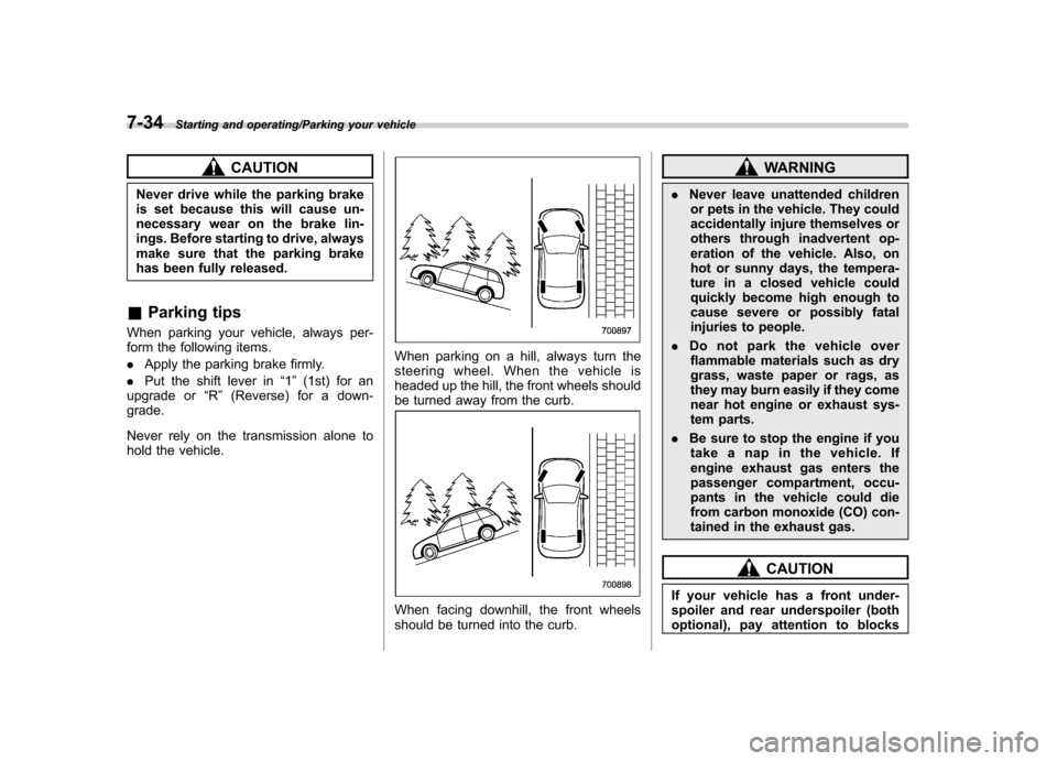
When parking on a hill, always turn the
steering wheel. When the vehicle is
headed up the hill, the front wheels should
be turned away from the curb.
When facing downhill, the front wheels
should be turned into the curb.
WARNING
. Never leave unattended children
or pets in the vehicle. They could
accidentally injure themselves or
others through inadvertent op-
eration of the vehicle. Also, on
hot or sunny days, the tempera-
ture in a closed vehicle could
quickly become high enough to
cause severe or possibly fatal
injuries to people.
. Do not park the vehicle over
flammable materials such as dry
grass, waste paper or rags, as
they may burn easily if they come
near hot engine or exhaust sys-
tem parts.
. Be sure to stop the engine if you
take a nap in the vehicle. If
engine exhaust gas enters the
passenger compartment, occu-
pants in the vehicle could die
from carbon monoxide (CO) con-
tained in the exhaust gas.
CAUTION
If your vehicle has a front under-
spoiler and rear underspoiler (both
optional), pay attention to blocks
Page 278 of 414
and other obstructions on the
ground when parking. The under-
spoilers could be damaged by con-
tact with them.Hill start assist system
CAUTION
The Hill start assist system is a
device only for helping the driver
to START the vehicle on an uphill
grade. To prevent accidents when
the vehicle is parked on a slope, be
sure to firmly set the parking brake.
When setting the parking brake,
make sure that the vehicle remains
stationary when the clutch pedal isreleased.
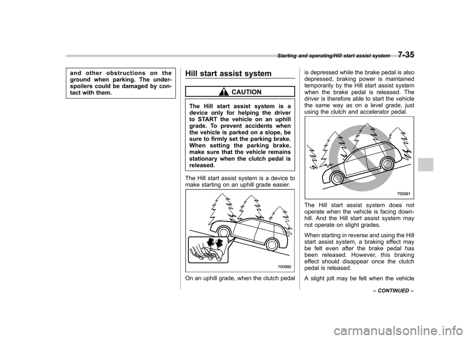
The Hill start assist system is a device to
make starting on an uphill grade easier.
On an uphill grade, when the clutch pedal is depressed while the brake pedal is also
depressed, braking power is maintained
temporarily by the Hill start assist system
when the brake pedal is released. The
driver is therefore able to start the vehicle
the same way as on a level grade, just
using the clutch and accelerator pedal.
The Hill start assist system does not
operate when the vehicle is facing down-
hill. And the Hill start assist system may
not operate on slight grades.
When starting in reverse and using the Hill
start assist system, a braking effect may
be felt even after the brake pedal has
been released. However, this braking
effect should disappear once the clutch
pedal is released.
A slight jolt may be felt when the vehicle
Starting and operating/Hill start assist system7-35
– CONTINUED –
Page 288 of 414

printed on the tire placard. The
tire placard is located on the
bottom of driver’s door pillar.
If all of four tires are not the same
for items (a) to (h), there is a
possibility that serious mechan-
ical damage could occur to the
drive train of your car, and affect
the following. — Ride
— Handling
— Braking
— Speedometer/Odometer
calibration— Clearance between the body
and tires
It also may be dangerous and
lead to loss of vehicle control,
and it can lead to an accident.
CAUTION
If you use a temporary spare tire to
replace a flat tire, be sure to use the
original temporary spare tire stored
in the vehicle. Using other sizes may
result in severe mechanical damage
to the drive train of your vehicle.
All-Wheel Drive distributes the engine
power to all four wheels. AWD models
provide better traction when driving on
slippery, wet or snow-covered roads and
when moving out of mud, dirt and sand.
By shifting power between the front and
rear wheels, SUBARU AWD can also
provide added traction during acceleration
and added engine braking force duringdeceleration.
Therefore, your SUBARU AWD vehicle
may handle differently than an ordinary
two wheel drive vehicle and it contains
some features unique to AWD. For safety
purposes as well as to avoid damaging
the AWD system, you should keep the
following tips in mind. . An AWD model is better able to climb
steeper roads under snowy or slippery conditions than a two wheel drive vehicle.
There is little difference in handling,
however, during extremely sharp turns or
sudden braking. Therefore, when driving
down a slope or turning corners, be sure
to reduce your speed and maintain an
ample distance from other vehicles. .
Always check the cold tire pressure
before starting to drive. The recom-
mended tire pressure is provided on the
tire placard, which is located under the
door latch on the driver ’s side.
. Frequent driving of an AWD model
under hard-driving conditions such as
steep hills or dusty roads will necessitate
more frequent replacement of the follow-
ing items than that specified in “Mainte-
nance schedule ”F 11-3.
– Engine oil
– Brake fluid
– Rear differential gear oil
– Manual transmission oil
. There are some precautions that you
must observe when towing your vehicle.
For detailed information, refer to “Towing ”
F 9-12.
Driving tips/Driving tips for AWD models8-5