2014 SUBARU IMPREZA WRX ABS
[x] Cancel search: ABSPage 137 of 414
3-22Instruments and controls/Warning and indicator lights
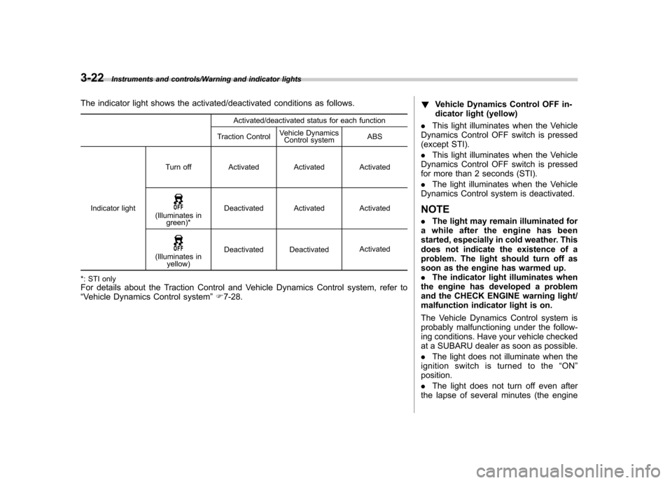
The indicator light shows the activated/deactivated conditions as follows.Activated/deactivated status for each function
Traction Control Vehicle Dynamics
Control system ABS
Indicator light Turn off Activated Activated Activated
(Illuminates in
green)* Deactivated Activated Activated
(Illuminates in
yellow) Deactivated Deactivated
Activated
*: STI only For details about the Traction Control and Vehicle Dynamics Control system, refer to “ Vehicle Dynamics Control system ”F 7-28. !
Vehicle Dynamics Control OFF in-
dicator light (yellow)
. This light illuminates when the Vehicle
Dynamics Control OFF switch is pressed
(except STI). . This light illuminates when the Vehicle
Dynamics Control OFF switch is pressed
for more than 2 seconds (STI). . The light illuminates when the Vehicle
Dynamics Control system is deactivated.
NOTE . The light may remain illuminated for
a while after the engine has been
started, especially in cold weather. This
does not indicate the existence of a
problem. The light should turn off as
soon as the engine has warmed up.. The indicator light illuminates when
the engine has developed a problem
and the CHECK ENGINE warning light/
malfunction indicator light is on.
The Vehicle Dynamics Control system is
probably malfunctioning under the follow-
ing conditions. Have your vehicle checked
at a SUBARU dealer as soon as possible. . The light does not illuminate when the
ignition switch is turned to the “ON ”
position.. The light does not turn off even after
the lapse of several minutes (the engine
Page 189 of 414
5-8Audio/Power and sound controls
!SRS CS Auto setting (type A audio)
SRS CS Auto can be set ON/OFF. When
this setting is ON, “
”is displayed on the
screen.
NOTE
SRS CS Auto creates a 5.1ch equiva-
lent surround field using 10 speakers
that are installed in the vehicle.
SRS CS Auto features:
1) Sound originating from door mount
speakers can be heard at ear level
(built in SRS FOCUS effect).
2) Ultra rich bass sound can be ob-
tained from standard door mount
speakers (built in SRS TruBass effect).
3) Surround sound can be obtained
from 2-channel stereo sources such as
CD, MP3 and FM (built in SRS Circle
Surround II effect).
4)SRSCSAutocanpositionthe
center channel image in the center of
the vehicle ’s windshield. This elimi-
nates the need for a center speaker
(built in SRS Circle Surround II phan-
tom center and SRS FOCUS effects).
CS Auto, TruBass, FOCUS, Circle Sur-
round-II, SRS and “
”symbol are
trademarks of SRS Labs, Inc.
CS Auto technology is incorporated under license from SRS Labs, inc.
Page 218 of 414
let on a circuit different from that to
which the receiver is connected..Consult the dealer or an experi-
enced radio/TV technician for help.. Changes or modifications not ex-
pressly approved by the party respon-
sible for compliance could void theuser ’s authority to operate the equip-
ment.. This equipment complies with FCC/
IC radiation exposure limits set forth
for an uncontrolled equipment and
meets the FCC radio frequency (RF)
Exposure Guidelines in Supplement C
to OET65 and RSS-102 of the IC radio
frequency (RF) Exposure rules. This
equipment has very low levels of RF
energy that it deemed to comply with-
out maximum permissive exposure
evaluation (MPE). But it is desirable
that it should be installed and operated
keeping the radiator at least 20 cm or
more away from person ’s body (ex-
cluding extremities: hands, wrists, feet
and ankles).. This transmitter must not be co-
located or operated in conjunction with
any other antenna or transmitter. &
Safety precautions
WARNING
. For safety reasons, avoid operat-
ing the cell phone while driving.
. Do not make a phone call while
driving. When you have an in-
coming call, stop the vehicle in a
safe location before taking the
incoming phone call. When you
have to absolutely take a phone
call, tell the caller “I’ll call you
back ”. And then call the caller
back after stopping the vehicle in
a safe location.
CAUTION
. Do not leave the cell phone in the
vehicle. The temperature in the
vehicle may become extremely
high and cause a malfunction of
the cell phone.
. When using the cell phone, be
careful not to get it close to the
in-vehicle equipment. Getting it
too close to the in-vehicle equip-
ment may result in deterioration
in tone quality or a poor connect-
ing condition. .
In the frequency band used by
this equipment, along with indus-
trial, scientific and medical
equipment such as a microwave
oven, radio stations (a license is
required) to be used by the
production line in the factory to
identify movable bodies, specific
small power radio stations (a
license is not required) and ama-
teur radio stations (a license is
required) are being operated.
(These three types of radio sta-
tions are hereinafter referred toas “other radio stations. ”) Before
using this equipment, be sure to
check to see if “other radio
stations ”are being operated in
the vicinity. If there is detrimental
radio interference from this
equipment to “other radio sta-
tions, ”move the equipment to
another location as soon as
possible to avoid radio interfer-
ence. The frequency band used
by this equipment is in the 2.4
GHz zone. The FH-SS modulation
is employed as a modulation
method. The expected inflicting
interference distance is less than
33 ft (10 m). This equipment uses
a full band and can avoid a band
Audio/Hands –free system5-37
– CONTINUED –
Page 244 of 414
Fuel...................................................................... 7-3
Fuel requirements ............................................... 7-3
Fuel filler lid and cap ........................................... 7-4
State emission testing (U.S. only) ...................... 7-7
Preparing to drive ............................................... 7-8
Starting the engine .............................................. 7-9
Stopping the engine ........................................... 7-10
Remote engine start system (dealer option) .............................................................. 7-10
Starting your vehicle .......................................... 7-10
Remote start safety features ............................... 7-11
Entering the vehicle while it is running via remote start ................................................................. 7-11
Entering the vehicle following remote engine start shutdown ......................................................... 7-11
Pre-heating or pre-cooling the interior of the vehicle ............................................................. 7-11
Service mode ..................................................... 7-11
Remote engine start transmitter programming and programmable feature option ..................... 7-12
System maintenance .......................................... 7-12
Manual transmission –6 speeds (STI) ............. 7-14
Selecting reverse gear ........................................ 7-15
Shifting speeds .................................................. 7-15
Driving tips ........................................................ 7-16
Manual transmission –5 speeds (except
STI) ................................................................... 7-16
Shifting speeds .................................................. 7-17
Driving tips ........................................................ 7-17 Driver
’s Control Center Differential (DCCD)
(STI) ................................................................. 7-18
To change mode of driver ’s control center
differential ....................................................... 7-18
Auto mode ........................................................ 7-19
Manual mode ..................................................... 7-20
Temporary release ............................................. 7-21
SI-DRIVE (STI) .................................................... 7-22
Intelligent (I) mode ............................................. 7-22
Sport (S) mode .................................................. 7-22
Sport Sharp (S#) mode. ...................................... 7-23
SI-DRIVE selector .............................................. 7-23
Limited slip differential (LSD) (STI) .................. 7-24
Power steering ................................................... 7-24
Braking ............................................................... 7-24
Braking tips ....................................................... 7-24
Brake system .................................................... 7-25
Disc brake pad wear warning indicators ............. 7-25
ABS (Anti-lock Brake System) .......................... 7-26
ABS system self-check ...................................... 7-26
ABS warning light .............................................. 7-26
Electronic Brake Force Distribution (EBD) system ............................................................. 7-27
Steps to take if EBD system malfunctions ..... ..... 7-27
Vehicle Dynamics Control system .................... 7-28
Vehicle Dynamics Control system monitor..... ..... 7-29
Vehicle Dynamics Control OFF switch (STI) ... ..... 7-30
Vehicle Dynamics Control OFF switch (except STI) ................................................................. 7-31 Starting and operating
7
Page 268 of 414
a loss of control of the vehicle. Keep
driving straight ahead while gradually
reducing speed. Then slowly pull off the
road to a safe place. &Brake system
! Two separate circuits
Your vehicle has two separate circuit
brake systems. Each circuit works diag-
onally across the vehicle. If one circuit of
the brake system should fail, the other half
of the system still works. If one circuit fails,
the brake pedal will go down much closer
to the floor than usual and you will need to
press it down much harder. And a much
longer distance will be needed to stop thevehicle. ! Brake booster
The brake booster uses engine manifold
vacuum to assist braking force. Do not
turn off the engine while driving because
that will turn off the brake booster, result-
ing in poor braking power.
The brakes will continue to work even
when the brake booster completely stops
functioning. If this happens, however, you
will have to depress the pedal much
harder than normal and the braking dis-
tance will increase. !
Brake assist system
WARNING
Do not be overconfident about the
brake assist. It is not a system that
brings more braking ability to the
vehicle beyond its braking capabil-
ity. Always use the utmost care
when driving regarding vehicle
speed and safe distance.
CAUTION
When you need to brake suddenly,
continue depressing the brake pedal
strongly to bring the effect of the
brake assist.
Brake assist is a driver assistance system.
It assists the brake power when the driver
cannot depress the brake pedal strongly
and the brake power is insufficient.
Brake assist generates the brake power
according to the speed at which the driver
depresses the brake pedal. NOTE
When you depress the brake pedal
strongly or suddenly, the following
phenomena occur. However, even
though these occur, they do not indi- cate any malfunctions, and the brake
assist system is operating properly. .
You might feel that the brake pedal
is applied by lighter force and gener-
ates a greater braking force.. You might hear the sound of ABS
operating from the engine compart-ment. & Disc brake pad wear warning indicators
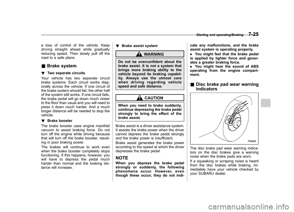
The disc brake pad wear warning indica-
tors on the disc brakes give a warning
noise when the brake pads are worn.
If a squeaking or scraping noise is heard
from the disc brakes while braking, im-
mediately have your vehicle checked by
your SUBARU dealer.
Starting and operating/Braking7-25
Page 269 of 414
7-26Starting and operating/ABS (Anti–lock Brake System)
ABS (Anti-lock Brake Sys- tem)
The ABS system prevents the lock-up of
wheels which may occur during sudden
braking or braking on slippery road sur-
faces. This helps prevent the loss of
steering control and directional stability
caused by wheel lock-up.
When the ABS system is operating, you
may hear a chattering noise or feel a slight
vibration in the brake pedal. This is normal
when the ABS operates.
The ABS system will not operate when the
vehicle speed is below approximately 6
mph (10 km/h).
WARNING
Always use the utmost care in driving –overconfidence because
youaredrivingwithanABS
equipped vehicle could easily lead
to a serious accident.
CAUTION
. The ABS system does not always
decrease stopping distance. You
should always maintain a safe following distance from othervehicles.
. When driving on badly surfaced
roads, gravel roads, icy roads, or
over deep newly fallen snow,
stopping distances may be long-
er for a vehicle with the ABS
system than one without. When
driving under these conditions,
therefore, reduce your speed and
leave ample distance from othervehicles.
. When you feel the ABS system
operating, you should maintain
constant brake pedal pressure.
Do not pump the brake pedal
since doing so may defeat the
operation of the ABS system.
& ABS system self-check
Just after the vehicle is started, you may
feel on the brake pedal a vibration similar
to when the ABS operates, and you may
also hear the sound of the ABS working
from the engine compartment. This is
caused by an automatic functional test of
the ABS system being carried out and
does not indicate any abnormal condition. &
ABS warning light
Refer to “ABS warning light ”F 3-18.
Page 270 of 414

Electronic Brake Force Dis-
tribution (EBD) system
The EBD system maximizes the effective-
ness of the brakes by allowing the rear
brakes to supply a greater proportion of
the braking force. It functions by adjusting
the distribution of braking force to the rear
wheels in accordance with the vehicle’s
loading condition and speed.
The EBD system is an integral part of the
ABS system and uses some of the ABSsystem ’s components to perform its func-
tion of optimizing the distribution of brak-
ing force. If any of the ABS components
used by the EBD system malfunction, the
EBD system also stops working.
When the EBD system is operating, you
may hear a chattering noise or feel a slight
vibration in the brake pedal. This is normal
and does not indicate a malfunction. &
Steps to take if EBD system malfunctions
If a malfunction occurs in the EBD system,
the system stops working and the brake
system warning light and ABS warning
light illuminate simultaneously.
The EBD system may be malfunctioning if
the brake system warning light and ABS
warning light illuminate simultaneously
during driving.
Even if the EBD system malfunctions, the
conventional braking system will still func-
tion. However, the rear wheels will be
more prone to locking when the brakes
are applied harder than usual and thevehicle ’s motion may therefore become
somewhat harder to control.
If the brake system warning light and ABS warning light illuminate simultaneously,
take the following steps.
1. Stop the vehicle in the nearest safe,
flat location.
2. Shut down the engine, apply the
parking brake, and then restart it.
3. Release the parking brake. If both
warning lights turn off, the EBD system
may be malfunctioning. Drive carefully to
the nearest SUBARU dealer and have the
system inspected.
4. If both warning lights illuminate again
and remain illuminated after the engine
has been restarted, shut down the engine
again, apply the parking brake, and check
the brake fluid level. Refer to
“Brake fluid ”
F 11-18.
5. If the brake fluid level is not below the“ MIN ”mark, the EBD system may be
malfunctioning. Drive carefully to the
nearest SUBARU dealer and have the
system inspected.
6. If the brake fluid level is below the “ MIN ”mark, DO NOT drive the vehicle.
Instead, have the vehicle towed to the
nearest SUBARU dealer for repair.
WARNING
. Driving with the brake system
warning light illuminated is dan-
Starting and operating/Electronic Brake Force Distribution (EBD) system7-27
– CONTINUED –
Page 272 of 414
of the Vehicle Dynamics Con-
trol system is reduced and
this should be taken into ac-
count when driving the vehi-
cle in such a condition.
. If non-matching tires are used,
the Vehicle Dynamics Control
system may not operate cor-
rectly.
. The Vehicle Dynamics Control
system helps prevent unstable
vehicle motion such as skidding
using control of the brakes and
engine power. Do not turn off the
Vehicle Dynamics Control sys-
tem unless it is absolutely ne-
cessary. If you must turn off the
Vehicle Dynamics Control sys-
tem, drive very carefully based
on the road surface condition.
In the event of wheelspin and/or skidding
on a slippery road surface and/or during
cornering and/or an evasive maneuver,
the Vehicle Dynamics Control system
adjusts the engine ’s output and the
wheels ’respective braking forces to help
maintain traction and directional control. . Traction Control Function
The traction control function is designed to
prevent spinning of the driving wheels on
slippery road surfaces, thereby helping to maintain traction and directional control.
Activation of this function is shown by
flashing the Vehicle Dynamics Control
operation indicator light. .
Skid Suppression Function
The skid suppression function is designed
to help maintain directional stability by
suppressing the wheels ’tendency to slide
sideways during steering operations. Acti-
vation of this function is shown by flashing
the Vehicle Dynamics Control operation
indicator light.
NOTE . The Vehicle Dynamics Control sys-
tem may be considered normal when
the following conditions occur.
–Slight twitching of the brake
pedal is felt. – The vehicle or steering wheel
shakes to a small degree.– An operating sound from the
engine compartment is heard
briefly when starting the engine
and when driving off after starting
the engine. – The brake pedal seems to jolt
when driving off after starting the engine.
. In the following circumstances, the
vehicle may be less stable than it feels to the driver. The Vehicle Dynamics
Control System may therefore operate.
Such operation does not indicate a
system malfunction.
–on gravel-covered or rutted
roads – on unfinished roads
– when the vehicle is fitted with
snow tires or winter tires
. Activation of the Vehicle Dynamics
Control system will cause operation of
the steering wheel to feel slightly
different compared to that for normalconditions. . It is always important to reduce
speed when approaching a corner,
even if the vehicle is equipped with
Vehicle Dynamics Control. . Always turn off the engine before
replacing a tire as failure to do so may
render the Vehicle Dynamics Control
system unable to operate correctly. & Vehicle Dynamics Control
system monitor
Refer to “Vehicle Dynamics Control warn-
ing light/Vehicle Dynamics Control opera-
tion indicator light ”F 3-20 and “Vehicle
Dynamics Control OFF indicator light/
Traction Control OFF indicator light (STI) ”
F 3-21.
Starting and operating/Vehicle Dynamics Control system7-29
– CONTINUED –