2014 SKODA SUPERB seat
[x] Cancel search: seatPage 122 of 246

WARNING (Continued)■Never leave a mobile phone on a seat, on the dash panel or in any area
from where it becomes a projectile during a sudden braking manoeuvre, an
accident or a collision — risk of injury.■
Before transport of the vehicle by air, the Bluetooth ®
function must be
switched off by a specialist company.
Universal telephone preinstallation (hands free)
The universal telephone preinstallation (“hands-free system”) includes a con- venience mode for the mobile phone via voice control, the multifunction steer-
ing wheel, the radio or navigation system.
WARNING■ Concentrate fully at all times on your driving! As the driver, you are fully
responsible for the operation of your vehicle.■
Only use the device in such a way that you are in full control of your vehi-
cle in every traffic situation – there is the risk of accidents!
■
The national regulations for using a mobile phone in a vehicle must be
observed.
Note■ We recommend that the installation of mobile phones and two-way radio
systems in a vehicle be carried out by a specialist firm.■
Not all mobile phones that enable Bluetooth ®
communication are compatible
with the universal telephone preinstallation GSM II or GSM III. Ask a ŠKODA Partner whether your phone is compatible with the universal telephone prepa-
ration GSM II or GSM III.
■
The range of the Bluetooth ®
connection to the hands-free system is restric-
ted to the vehicle interior. The range is dependent on local factors, e.g. obsta-
cles between the devices and mutual interferences with other devices. If your
mobile phone is in a jacket pocket, for example, this can lead to difficulties
when establishing a connection with the hands-free-system or transferring
data.
Operating the phone on the multifunction steering wheel
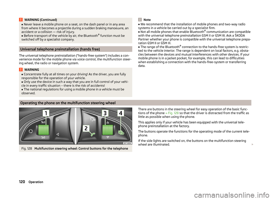
Fig. 128
Multifunction steering wheel: Control buttons for the telephone
There are buttons in the steering wheel for easy operation of the basic func-
tions of the phone » Fig. 128 so that the driver is distracted from the traffic as
little as possible when using the phone.
This applies only if your vehicle has been equipped with the universal tele-
phone preinstallation at the factory.
The buttons operate the functions for the operating mode of the current tele-
phone.
If the side lights are switched on, the buttons on the multifunction steering
wheel are illuminated. 120Operation
Page 135 of 246

Button/wheel
» Fig. 13 0
ActionRadioTVAudio sourcesDVD videoNavigation
5
Turn upwardsSwitch to the previous station and at the same time
display list of saved/available stationsSkip to next chan- nelSkip to next trackSkip to next chap- terShow the option
to stop navigation or display the list
of recent destina- tions5
Turn downwardsSwitch to the next station and at the same time
display list of saved/available stationsSwitch to previous channelSwitch to start of tracka)Switch to previous
chapter6Press brieflyCall up the main menua)
To go to the previous track, press the adjustment wheel twice or rotate it by two positions.
AUX- and MDIinputs
The AUX and MDI inputs are used to connect external audio sources (e.g. iPod
or mp3 player) and to play back music from these devices via the factory-fitted
radio or navigation system.
The AUX input for external audio sources is located below the armrest of the
front seats and is marked with the symbol. 1)
.
The MDI input is located in the storage compartment below the front armrest.
For a description of use, refer to the relevant operating instructions for the ra-
dio or navigation system.
CD change
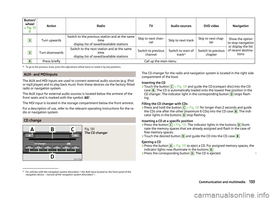
Fig. 131
The CD changer
The CD changer for the radio and navigation system is located in the right side
compartment of the boot.
Inserting the CD›
Touch the button
C
» Fig. 131 and guide the CD (compact disc) into the CD-
case
B
. The CD is automatically loaded onto the lowest free position in the
CD changer. The indicator light in the corresponding button
D
stops flash-
ing.
Filling the CD changer with CDs
›
Press and hold the button
C
» Fig. 131 for longer than 2 seconds and guide
the CDs one after the other (maximum 6 CDs) into the CD case
B
. The indi-
cator lights in the buttons
D
stop flashing.
Inserting a CD at a specific position
›
Press the button
C
» Fig. 131 . The indicator lights in the buttons
D
illumi-
nate the memory spaces that are already assigned and flash in the case of
free memory spaces.
›
Touch the desired button
D
and guide the CD into the CD-case
B
.
Ejecting a CD
›
Press the button
A
» Fig. 131 to eject a CD. For assigned memory spaces, the
indicator lights now illuminate in the buttons
D
.
›
Press the corresponding button
D
. The CD is ejected.
1)
For vehicles with the navigation system Amundsen + the AUX input located on the front panel of the
navigation device » manual of the navigation system Amundsen + .
133Communication and multimedia
Page 136 of 246

Ejecting all CDs›Press and hold the button A » Fig. 131 for more than 2 seconds. All CDs in
the CD-changer are ejected consecutively.
Note
■ Insert a CD, with the labelled side facing up, into the CD slot B » Fig. 131 until
it is automatically drawn in. The play function will start automatically.■
After loading a CD into the CD changer, wait until the indicator light of the
corresponding button
D
is illuminated. Then the CD case
B
is free to load the
next CD.
■
If a position is selected, on which a CD is already located, this CD is ejected.
Remove the ejected CD and load the desired CD.
DVD-preinstallation
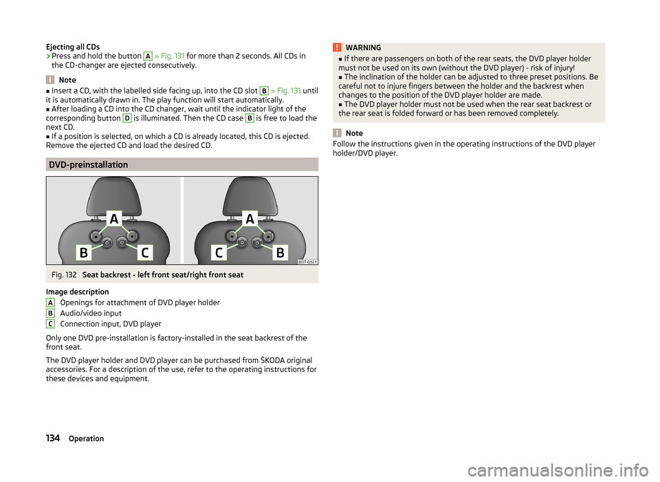
Fig. 132
Seat backrest - left front seat/right front seat
Image description Openings for attachment of DVD player holder
Audio/video input
Connection input, DVD player
Only one DVD pre-installation is factory-installed in the seat backrest of the
front seat.
The DVD player holder and DVD player can be purchased from ŠKODA original
accessories. For a description of the use, refer to the operating instructions for
these devices and equipment.
ABCWARNING■ If there are passengers on both of the rear seats, the DVD player holder
must not be used on its own (without the DVD player) - risk of injury!■
The inclination of the holder can be adjusted to three preset positions. Be
careful not to injure fingers between the holder and the backrest when
changes to the position of the DVD player holder are made.
■
The DVD player holder must not be used when the rear seat backrest or
the rear seat is folded forward or has been removed completely.
Note
Follow the instructions given in the operating instructions of the DVD player
holder/DVD player.134Operation
Page 162 of 246

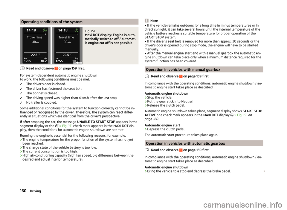
Operating conditions of the systemFig. 151
Maxi DOT display: Engine is auto-
matically switched off / automat-
ic engine cut off is not possible
Read and observe on page 159 first.
For system-dependent automatic engine shutdown
to work, the following conditions must be met.
The driver's door is closed.
The driver has fastened the seat belt.
The bonnet is closed.
The driving speed was higher than 4 km.h after the last stop.
No trailer is coupled.
Some additional conditions for the system to function correctly cannot be in-
fluenced or recognised by the driver. Therefore, the system can react differ-
ently in situations which are identical from the driver's perspective.
If after stopping the car, the message UNABLE TO START STOP appears in the
segment display or the
» Fig. 151 check mark appears in the MAXI DOT dis-
play, then the conditions for automatic engine shutdown are not met.
Running the engine is essential for the following reasons, for example.
› The engine temperature for the proper function of the system has not yet
been reached.
› The charge state of the vehicle battery is too low.
› The current consumption is too high.
› High air-conditioning capacity (high fan speed, big difference between the
desired and actual interior temperature).
Note■ If the vehicle remains outdoors for a long time in minus temperatures or in
direct sunlight, it can take several hours until the internal temperature of the
vehicle battery reaches a suitable temperature for proper operation of the
START STOP system.■
If the driver's seat belt is removed for more than approx. 30 seconds or the
driver's door is opened during stop mode, the engine will have to be started
manually.
■
After the manual engine start and with a manual gearbox the automatic en-
gine shutdown can take place only when a minimum distance required for the
system function has been covered.
Operation in vehicles with manual gearbox
Read and observe
on page 159 first.
In compliance with the operating conditions, automatic engine shutdown / au-
tomatic engine start takes place as described.
Automatic engine shutdown
›
Stop the vehicle.
›
Put the gear stick into Neutral.
›
Release the clutch pedal.
Automatic engine shutdown takes place, segment display shows START STOP
ACTIVE or a check mark appears in the MAXI DOT display
» Fig. 151 on
page 160 .
Automatic engine start
›
Depress the clutch pedal.
The automatic start procedure takes place again.
Operation in vehicles with automatic gearbox
Read and observe
on page 159 first.
In compliance with the operating conditions, automatic engine shutdown / au-
tomatic engine start takes place as described.
Automatic engine shutdown
›
Bring the vehicle to a stop and depress the brake pedal.
160Driving
Page 163 of 246

Automatic engine shutdown takes place, segment display shows START STOP
ACTIVE or a check mark appears in the MAXI DOT display » Fig. 151 on
page 160 .
Automatic engine start›
Release the brake pedal.
The automatic start procedure takes place again.
Further information on automatic transmission
The automatic engine shut down takes place when the selector lever is in po-
sitions P, D , S and N and in Tiptronic mode.
When the selector lever is in position P, the engine remains shut down even
after you release the brake pedal. The engine starts automatically by pressing
the gas pedal or by moving the selector lever into a different mode and releas-
ing the brake pedal.
If the engine is off due to the automatic and the selector lever is put to the R
position then the automatic starts the engine.
If the gear selector is moved from position R to the position D, S or N, the vehi-
cle must reach a speed of more than 10 km / h before the automatic engine
shutdown starts.
There is no automatic engine shutdown when the system detects a vehicle
moving due to a large steering angle.
No automatic engine shutdown takes place when the vehicle is moving at low
speed (e.g. during a traffic jam or when tuning) and remains stationary after
pressing the brake pedal lightly. Automatic engine shutdown takes place if you
press the brake pedal down with more force.
System related automatic start-up
Read and observe
on page 159 first.
When the engine is off, the system can automatically start the engine before
the desired journey continues. Some possible reasons for this are:
› The vehicle begins to roll, e.g. on a slope.
› The brake pedal has been actuated several times.
› The current consumption is too high.
Manually deactivating/activating the systemFig. 152
Button for the START-STOP sys-
tem
Read and observe on page 159 first.
Deactivating/activating
›
Press the button
» Fig. 152 .
When start-stop mode is deactivated, the indicator light in the button lights
up.
Note
If the system is deactivated when the engine is turned off automatically, then
the automatic start process takes place.
Information messages
Read and observe
on page 159 first.
The messages and information are indicated in the instrument cluster display. Start the engine manually!
START MANUALLY
One of the conditions for automatic engine start is not satisfied or the driver's
seat belt is not fastened. The engine must be started manually.
On vehicles with the system KESSY the ignition is turned off by the first press
of the start button, only after pressing for the second time is the start process
initiated.
Error: Start-stop system
ERROR START-STOP
A system error is present. Seek help from a specialist garage.
161Assist systems
Page 164 of 246

Fatigue detection (break recommendation)
Introduction
This chapter contains information on the following subjects:
Function
162
Information messages
162WARNING■ For the driving ability is always the driver's responsibility. Never drive if
you feel tired.■
The system may not detect all cases where a break is needed.
■
Therefore, take regular, sufficient breaks during long trips.
■
There will be no system warning during the so-called micro-sleep.
Note
■ In some situations, the system may evaluate the driving incorrectly and thus
mistakenly recommend a break (e.g. sporty driving, adverse weather condi-
tions or poor road conditions).■
The fatigue detection system is designed primarily for motorway driving.
Function
Read and observe
on page 162 first.
The fatigue detection system advises the driver on the basis of informationabout the steering behaviour, to take a break from driving. The system recom-
mends a break at speeds of 65-200 km/h.
After the ignition has been switched on, the system evaluates the steering be-
haviour for 15 minutes. This baseline analysis is constantly compared with the
current steering behaviour.
If the system detects deviations from normal steering behaviour due to possi-
ble fatigue of the driver, it recommends to take a break from driving.
The system deletes the stored baseline analysis if one of the following con-
ditions is met.
› The vehicle is stopped and the ignition switched off.
› The vehicle is stopped, the seat belt removed and the driver's door opened.
› The vehicle is stopped for more than 15 minutes.
If none of these conditions are met or if the driving style is not changed, the
system recommends a driving break again after 15 minutes.
Activation/deactivation
The system can be activated/deactivated via the MAXI DOT display in the Wiz-
ards menu option » page 44.
Information messages
Read and observe
on page 162 first.
In MAXI DOT display the icon appears for a few seconds and the following
message.
Fatigue detected. Take a break!
An audible signal is also emitted.
162Driving
Page 165 of 246

Towing a trailer
Towing device
Introduction
This chapter contains information on the following subjects:
Description
163
Adjusting the ready position
164
Fitting the ball head
164
Check proper fitting
165
Removing the ball head
165
Use and care
166
If your vehicle has already been factory-fitted with a towing device or is fitted
with a towing device from ŠKODA Original Accessories, then it meets all of the
technical requirements and national legal regulations for towing a trailer.
Your vehicle is fitted with a 13-pin power socket for the electrical connection
between the vehicle and trailer. If the trailer that is to be towed has a 7-pin
connector , you can use a suitable adapter from ŠKODA Original Accessories.
The maximum trailer drawbar load is 80 kg.
WARNING■
Check that the tow bar is seated correctly and is secured in the mounting
recess before the start of every journey.■
Do not use the tow bar if it is not correctly inserted and secured in the
mounting recess.
■
Do not use the towing device if it is damaged or if there are parts missing.
■
Do not modify or adapt the towing device in any way.
■
Never release the tow bar while the trailer is still coupled.
CAUTION
Take care when handling the tow bar so as to avoid damaging the paintwork
on the bumper.DescriptionFig. 153
Carrier for the towing device/tow bar
Read and observe
and on page 163 first.
The tow bar can be removed and is kept in the spare wheel compartment or in
a compartment for the spare wheel in the boot » page 201, Vehicle tool kit .
Image description » Fig. 153
13-pin power socket
Safety eyelet
Mounting recess
Cap
Dust cap
Tow ball
Operating lever
Lock cap
Release pin
Key
Locking ball
Note
If you lose the key, please get in touch with a specialist garage.1234567891011163Towing a trailer
Page 173 of 246

ŠKODA service partners are liable for any ŠKODA Genuine Part defects for aperiod of 2 years after installation or delivery in accordance with the materials
defect liability, provided that nothing else was agreed in the purchase contract
or in any other agreements. You should keep the approved warranty certificate
and the bill for these components for this period of time, so that commence-
ment of the term may be verified.
In addition, ŠKODA Service Partners also stock a range of suitable car care
products as well as those parts which are subject to natural wear-and-tear,
such as tyres, batteries, bulbs and wiper blades.
Note
The accessories authorized by the company ŠKODA AUTO a.s. will be offered
by the ŠKODA partners in all countries where the company ŠKODA AUTO a.s.
has a sales and service network. This will usually be in the form of a printed
catalogue of Original ŠKODA Accessories, in the form of separate printed bro-
chures or in the form of offers for ŠKODA Genuine Accessories on the ŠKODA
partner web pages.
Spoiler
Read and observe
on page 169 first.
If your new vehicle is fitted with a spoiler on the front bumper in combination
with the spoiler on the luggage compartment lid, the following instructions
must be adhered to.
› For safety reasons, the vehicle must only be fitted with a spoiler on the front
bumper in combination with the associated spoiler on the luggage compart-
ment lid.
› This kind of spoiler cannot be left on the front bumper either on its own, in
combination with another spoiler not on the luggage compartment lid or in
combination with an unsuitable spoiler on the luggage compartment lid.
› We recommend that you consult the ŠKODA Service Partner for any repairs
to or replacement, addition or removal of spoilers.
WARNINGIf work on your vehicle's spoilers is not carried out properly, this can lead to
operational faults - risk of accident and serious injuries.Airbags
Read and observe
on page 169 first.
The system components of the airbag system can be situated in the front
bumper, doors, front seats, roof lining or body.
WARNINGAny work on the airbag system including the installation and removal of
system components due to other repair work (e.g. removal of the steering
wheel) must only be carried out by a specialist garage.■
Modifications, repairs and technical alterations that have been carried out
unprofessionally can cause damage and operational faults, and can also se-
riously impair the effectiveness of the airbag system – risk of accident and
fatal injury!
■
The airbag system must then be replaced if the airbag has been deployed.
Airbag modules cannot be repaired.
WARNINGInformation on the use of the airbag system■It is prohibited to manipulate individual parts of the airbag system, as this
might result in the airbag being deployed.■
Never install any airbag parts into the vehicle that have been removed
from old cars or have been recycled.
■
Never install damaged airbag parts in the vehicle. The airbags may then
not be deployed properly or even at all in the event of an accident.
■
No modifications of any kind must be made to parts of the airbag system.
WARNING■ A change to the vehicle's wheel suspension, including the use of non-ap-
proved wheels and tire combinations, can alter the functioning of the air-
bag system - risk of accident and fatal injury!■
Never make any changes to the front bumper or the bodywork.
171Car care