2014 SKODA ROOMSTER warning lights
[x] Cancel search: warning lightsPage 63 of 204

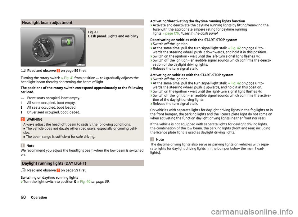
Headlight beam adjustmentFig. 41
Dash panel: Lights and visibility
Read and observe on page 59 first.
Turning the rotary switch » Fig. 41 from position
to
gradually adjusts the
headlight beam thereby shortening the beam of light.
The positions of the rotary switch correspond approximately to the following
car load.
Front seats occupied, boot empty.
All seats occupied, boot empty.
All seats occupied, boot loaded.
Driver seat occupied, boot loaded.
WARNINGAlways adjust the headlight beam to satisfy the following conditions.■The vehicle does not dazzle other road users, especially oncoming vehi-
cles.■
The beam range is sufficient for safe driving.
Note
We recommend you adjust the headlight beam when the low beam is switched
on.
Daylight running lights (DAY LIGHT)
Read and observe
on page 59 first.
Switching on daytime running lights
›
Turn the light switch to position 0 » Fig. 40 on page 59 .
Activating/deactivating the daytime running lights function›Activate and deactivate the daytime running lights by fitting/removing the
fuse with the appropriate ampere rating for daytime running
lights » page 176 , Fuses in the dash panel .
Deactivating on vehicles with the START-STOP system›
Switch off the ignition.
›
At the same time, pull the turn signal light stalk » Fig. 42 on page 61 to-
wards the steering wheel, push it downwards, and hold it in this position.
›
Switch on the ignition - wait until the left-turn signal light flashes 4x.
›
Switch off the ignition - an audible signal sounds which confirms the deacti-
vation of the daylight driving lights.
›
Release the turn signal stalk.
Activating on vehicles with the START-STOP system
›
Switch off the ignition.
›
At the same time, pull the turn signal light stalk » Fig. 42 on page 61 to-
wards the steering wheel, push it upwards, and hold it in this position.
›
Switch on the ignition - wait until the right-turn signal light flashes 4x.
›
Switch off the ignition - an audible signal sounds which confirms the activa-
tion of the daylight driving lights.
›
Release the turn signal stalk.
On vehicles with separate lights for daylight driving lights in the fog lights or in
the front bumper, the parking lights and the licence plate light do not come on
when activating the function daylight driving lights (neither front nor rear).
If the vehicle is not equipped with separate lights for daylight driving lights,
the combination of the low beam, the parking lights (front and rear) including
the licence plate light is used as daylight driving lights.
Note
The daytime driving lights also serve as parking lights on vehicles with sepa-
rate lights for daylight driving lights (in the bumper below the main head-
lights).60Operation
Page 64 of 204

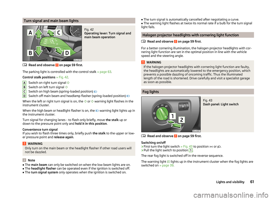
Turn signal and main beam lightsFig. 42
Operating lever: Turn signal and
main beam operation
Read and observe on page 59 first.
The parking light is controlled with the control stalk » page 63.
Control stalk positions » Fig. 42 .
Switch on right turn signal
Switch on left turn signal
Switch on high beam (spring-loaded position)
Switch off main beam and headlamp flasher (spring-loaded position)
When the left or right turn signal is on, the or
warning light flashes in the
instrument cluster.
When the high beam or headlight flasher is on, the warning light lights up in
the instrument cluster.
Turn signal for changing lanes - to flash only briefly, move the stalk up or
down to the pressure point only and hold it in this position.
Convenience turn signal
If you wish to flash three times only, briefly push the stalk to the upper or low-
er pressure point and release again.
WARNINGOnly turn on the main beam or the headlight flasher if other road users will
not be dazzled.
Note
■ The main beam can only be switched on when the low beam lights are on.■The headlight flasher can be operated even if the ignition is switched off.■
The turn signal system only operates when the ignition is switched on.
ABCD■
The turn signal is automatically cancelled after negotiating a curve.■The warning light flashes at twice its normal rate if a bulb for the turn signal
light fails.
Halogen projector headlights with cornering light function
Read and observe
on page 59 first.
For a better cornering illumination, the halogen projector headlights with cor-nering light function are set in the optimal position in line with the vehicle
speed and the steering angle.
WARNINGIf the halogen projector headlights with cornering light function are faulty,
the headlights are automatically lowered to the emergency position, which
prevents a possible dazzling of oncoming traffic. Thus the illuminated
length of the road is shortened. Drive carefully and visit a specialist garage
as soon as possible.
Fog lights
Fig. 43
Dash panel: Light switch
Read and observe on page 59 first.
Switching on/off
›
First turn the light switch » Fig. 43 to position
or
.
›
Pull the light switch to position
1
.
The rear fog light is switched off in the reverse sequence.
The warning light
lights up in the instrument cluster when the fog lights are
switched on » page 39.
61Lights and visibility
Page 65 of 204

Foglights with the CORNER functionRead and observe
on page 59 first.
The CORNER function lights the front fog lamp on the relevant side of the ve-hicle to illuminate the area around the vehicle when turning, parking, etc.
The CORNER function is switched on automatically if the following conditions
are met.
› The turn signal is switched on or the front wheels are turned sharply to the
right or left 1)
.
› The engine is running.
› The vehicle is stopped or moves at a speed of no more than 40 km/h.
› The low beam is switched on.
› The daytime running lights are not switched on.
› The fog lights are not switched on.
› Reverse gear is not engaged.
Rear fog light
Read and observe
on page 59 first.
Switching on/off
›
First turn the light switch » Fig. 43 on page 61 to position
or
.
›
Pull the light switch to position
2
.
The rear fog light is switched off in the reverse sequence.
If the vehicle is not fitted with fog lights, the rear fog light is switched on by pulling out the light switch directly to the only possible setting.
The warning light lights up in the instrument cluster when the rear fog light
is switched on » page 39.
Only the rear fog light on the trailer lights up if the vehicle has a factory-fitted
towing device or a towing device from ŠKODA original accessories and it is
driven with a trailer.
Tourist lights
Read and observe
on page 59 first.
Halogen projector headlights with cornering light function
This mode makes it possible to drive in countries with opposing traffic system
(driving on the left/right) without dazzling the oncoming vehicles. When the
mode “tourist light” is active, the side to side swivel of the headlights is deacti-
vated.
Activating tourist light
Before activating the tourist light, the following conditions must be met.
Ignition switched off, light switched off (light switch in position 0), control dial
for headlamp beam adjustment in the position, no gear engaged or selector
lever in the N position (automatic gearbox), tourist light deactivated.
›
Switch on the ignition.
Within 10 seconds of the ignition being switched on:
›
Turn the light switch to the position
» page 59 , Switching the light on/off .
›
Engage reverse gear (manual gearbox) or move the selector lever to the R
position (automatic gearbox),
›
Turn the headlamp beam adjustment dial from to
» page 60 .
Deactivating tourist light
Before deactivating the tourist light, the following conditions must be met.
Ignition switched off, light switched off (light switch in position 0), control dial
for headlamp beam adjustment in the position, no gear engaged or selector
lever in the N position (automatic gearbox), tourist light activated.
›
Switch on the ignition.
Within 10 seconds of the ignition being switched on:
›
Turn the light switch to the position
» page 59 , Switching the light on/off .
›
Engage reverse gear (manual gearbox) or move the selector lever to the R
position (automatic gearbox),
›
Turn the headlamp beam adjustment dial from to
» page 60 .
Further information » page 118, Headlights .
1)
If both switch on versions are conflicting, for example if the steering wheel is turned to the left and the
right turn signal light is switched on, the turn signal light has the higher priority.
62Operation
Page 66 of 204

NoteWhen the “tourist light” mode is active, the warning light flashes for 10 sec-
onds each time the ignition is switched on.
Hazard warning light system
Fig. 44
Dash panel: Button for hazard
warning light system
Read and observe on page 59 first.
›
Press the
» Fig. 44 button.
All the turn signal lights on the vehicle flash at the same time when the hazard
warning light system is switched on. The warning light for the turn signals and
the warning light in the button also flash at the same time. The hazard warn-
ing light system can also be operated if the ignition is switched off.
The hazard warning light system will switch on automatically if one of the air-
bags is deployed.
CAUTION
Switch on the hazard warning light system if, for example, the following oc-
curs.■
You encounter a traffic jam.
■
The vehicle has broken down.
Parking lights
Read and observe
on page 59 first.
Switching on the parking light
›
Switch off the ignition.
›
Pull the turn signal stalk
» Fig. 42 on page 61 upwards or downwards - the
side light on the right or left side of the vehicle is switched on.
Switching on the side lights on both sides ›Turn the light switch » Fig. 40 on page 59 to the position and lock the ve-
hicle.
Note
■ The parking light can only be activated if the ignition is switched off.■If the right or left turn signal light has been switched on and the ignition is
switched off, the parking light is not automatically switched on.
Interior lights
Introduction
This chapter contains information on the following subjects:
Interior lighting - version 1
63
Interior lighting - version 2
64
Illuminated storage compartment on the passenger side
64
Luggage compartment light
64
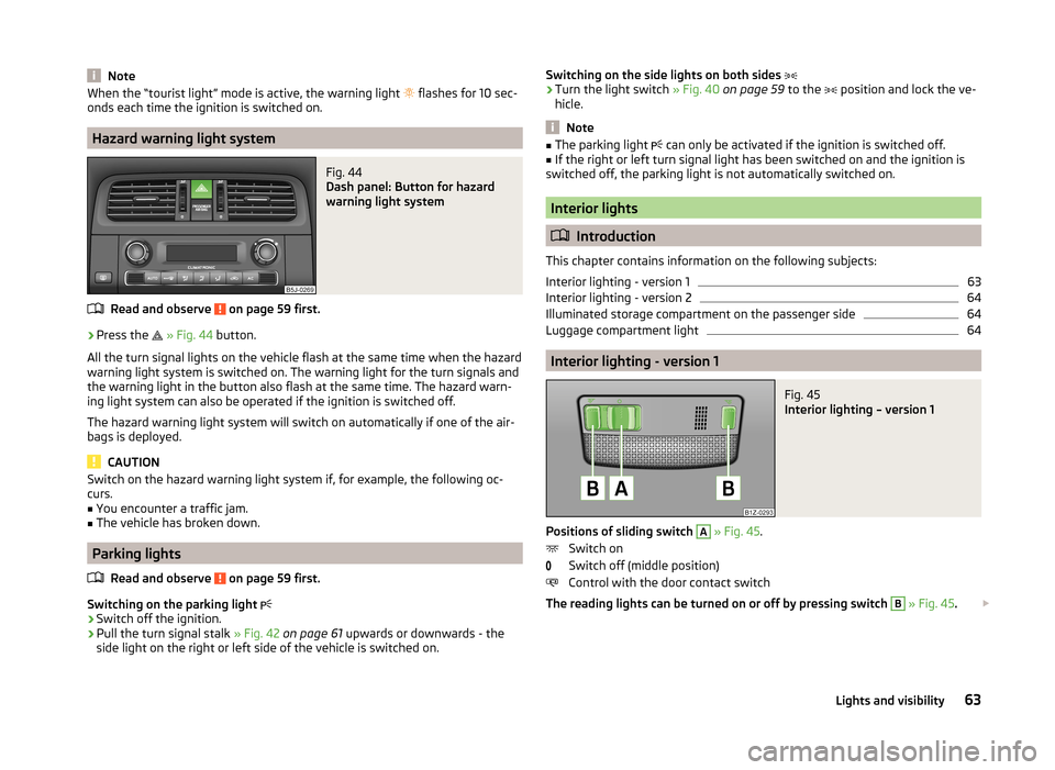
Interior lighting - version 1
Fig. 45
Interior lighting – version 1
Positions of sliding switch
A
» Fig. 45 .
Switch on
Switch off (middle position)
Control with the door contact switch
The reading lights can be turned on or off by pressing switch
B
» Fig. 45 .
63Lights and visibility
Page 67 of 204

If control of the lights by the door contact switch is enabled (switchA » Fig. 45 is in the position), the light will come on when one of the fol-
lowing occurs.
› The vehicle is unlocked.
› One of the doors is opened.
› The ignition key is removed.
If control of the lights by the door contact switch is enabled (switch A
» Fig. 45
in the
position), the light will go off when one of the following occurs.
› The vehicle is locked.
› The ignition is switched on.
› About 30 seconds after all the doors have been closed.
If a door remains open, or if switch
A
» Fig. 45 is in the
position, the interior
light goes out after 10 minutes to prevent the vehicle battery from discharging.
Interior lighting - version 2
Fig. 46
Interior lighting – version 2
Slide switch positions » Fig. 46 .
Switch on
Switch off
Control by the door contact switch (middle position)
The same principles apply for interior lighting version 2 as for » page 63, Interi-
or lighting - version 1 .
Illuminated storage compartment on the passenger side
›
When opening the flap of the storage compartment on the front passenger
side the lighting in the storage compartment comes on.
›
The light switches on automatically when the parking light is switched on
and goes out when the flap is closed.
Luggage compartment light
The light comes on automatically when the boot lid is opened. If the tailgate remains open for more than 10 minutes, the luggage compartment light
switches off automatically.
Visibility
Introduction
This chapter contains information on the following subjects:
Rear window heater
64
Sun visors
65
sunshade
65
Rear window heater
Fig. 47
Button for rear window heater
›
The rear window heater is switched on or off by pressing the but-
ton » Fig. 47 , the warning light in the switch comes on or goes out.
The rear window heater can only be switched on when the engine is running.
The rear window heater switches off automatically after approximately 7 mi-
nutes.
For the sake of the environment
The heating should be switched off as soon as the window is de-iced or free
from mist. The reduced current consumption will have a favourable effect on
fuel economy » page 116, Saving electrical energy . 64Operation
Page 68 of 204

NoteIf the on-board voltage drops, the rear window heater switches off automati-
cally, in order to provide sufficient electrical energy for the engine con-
trol » page 156 , Automatic load deactivation .
Sun visors
Fig. 48
Sun visor: swivelling out
The sun visor for the driver or front passenger can be pulled out of the fixture
and swivelled towards the door in the direction of arrow
1
» Fig. 48 .
The vanity mirrors in the sun visors are provided with covers. Push the cover in
the direction of the arrow
2
.
The purpose of the strap
A
is to store small, light objects, such as a notepad,
etc.
WARNINGThe sun visors must not be swivelled towards the side windows in the de-
ployment area of the head airbags if any objects, such as ball-point pens,
etc. are attached to them. This might result in injuries to the occupants if
the head airbag is deployed.sunshadeFig. 49
Sun screen
The sunshade can be opened or closed manually » Fig. 49.
Please pay attention to the following points if you wish to transport luggage
or other items on the roof of your vehicle » page 80,
in section Introduc-
tion .
WARNINGWhen operating the sunshade, proceed with caution to avoid causing
crushing injuries – risk of injury!
Windscreen wipers and washers
Introduction
This chapter contains information on the following subjects:
Windscreen wiper and washer
66
Headlight cleaning system
67
Replacing the windscreen wiper blades
67
Replacing the rear window wiper blade
67
The windscreen wipers and the windscreen washer system only operate when
the ignition is switched on.
The rear window is wiped once automatically if the windscreen wipers are on
when reverse gear is selected.
Top up with windscreen wiper fluid » page 147.
65Lights and visibility
Page 95 of 204

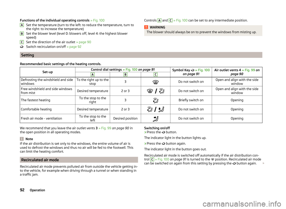
Functions of the individual operating controls » Fig. 100
Set the temperature (turn to the left: to reduce the temperature, turn to
the right: to increase the temperature)
Set the blower level (level 0: blowers off, level 4: the highest blower
speed)
Set the direction of the air outlet » page 90
Switch recirculation on/off » page 92ABCControls A and C » Fig. 100 can be set to any intermediate position.WARNINGThe blower should always be on to prevent the windows from misting up.
Setting
Recommended basic settings of the heating controls.Set-upControl dial settings » Fig. 100 on page 91Symbol Key » Fig. 100
on page 91Air outlet vents 4 » Fig. 99 on
page 90ABCDefrosting the windshield and side
windowsTo the right up to the stop3Do not switch onOpen and align with the side windowFree windshield and side windows
from mistDesired temperature2 or 3
Do not switch onOpen and align with the side
windowThe fastest heatingTo the stop to theright3Briefly switch onOpeningComfortable heatingDesired temperature2 or 3
Do not switch onOpeningFresh air mode - ventilationTo the stop to the
leftDesired positionDo not switch onOpeningWe recommend that you leave the air outlet vents 3 » Fig. 99 on page 90 in
the open position in all operating modes.
Note
If the air distribution is set only to the windows, the entire volume of air is
used to defrost the windows and thus no air will be fed to the footwell. This
can limit the heating comfort.
Recirculated air mode
Recirculated air mode prevents polluted air from outside the vehicle getting in-
to the vehicle, for example when driving through a tunnel or when standing in
a traffic jam.
Switching on/off›Press the button.
The indicator light in the button lights up.›
Press the
button again.
The indicator light in the button goes out.
Recirculated air mode is switched off automatically if the air distribution con-
trol
C
» Fig. 100 on page 91 is turned to the
position. Recirculated air mode
can be switched on again from this setting by pressing the
button again.
92Operation
Page 96 of 204

WARNINGNever leave recirculated air mode on over a longer period of time, as “stale
air” can cause fatigue of the driver and the passengers, reduce attention
levels and also cause the windows to mist up. The risk of having an acci-
dent increases. Switch off recirculated air mode as soon as the windows
start to mist up.
Air conditioning system (manual air conditioning system)
Introduction
This chapter contains information on the following subjects:
Operation
93
Setting the air conditioning system
94
Recirculated air mode
94
The cooling system operates only if the following conditions are met. The cooling system is switched on » page 93.
The engine is running.
The outside temperature is above approximately +2 °C.
The blower switch is switched on (positions 1-4).
If the desired interior temperature can also be achieved without activating the
cooling system, fresh air mode should be selected.
If the coolant temperature is too high, the cooling system is switched off to
ensure that the engine cools down.
CAUTION
■ Under certain circumstances, air at a temperature of about 5 °C can flow out
of the vents when the cooling system is switched on.■
Lengthy and uneven distribution of the air flow out of the vents (especially
around the feet) and large differences in temperature, for example, when get-
ting out of the vehicle, can cause susceptible individuals to catch a cold.
Note
■ We recommend that you have the air conditioning system cleaned by a spe-
cialist garage once every year.■
During operation of the air conditioning, an increase in engine idle speed may
occur under certain circumstances in order to ensure sufficient heating com-
fort.
OperationFig. 101
The air conditioning system: Control elements
Read and observe
on page 93 first.
Functions of the individual operating controls » Fig. 101
Set the temperature (turn to the left: to reduce the temperature, turn to
the right: to increase the temperature)
Set the blower level (level 0: blowers off, level 4: the highest blower
speed)
Set the direction of the air outlet » page 90
Switch recirculation on/off » page 94
Switch the cooling system on/off
Note
The warning light in the symbol button lights after activation, even if not all
of the conditions for the function of the cooling system are met » page 93. The
operational readiness of the cooling system is indicated by the indicator light
in the button lighting up.ABC93Heating and air-conditioning