Page 15 of 455
1. Battery (P. 8-14)
2. Fuse/fusible link box (P. 8-22)
3. Transmission dipstick (P. 8-11)
4. Engine oil filler cap (P. 8-9)
5. Brake fluid reservoir (P. 8-13)
6. Windshield-washer fluid reservoir(P. 8-13)
7. Air cleaner (P. 8-18)
8. Drive belt location (P. 8-16)
9. Radiator cap (P. 8-7)
10. Power steering fluid reservoir (P. 8-12)
11. Engine oil dipstick (P. 8-9)
12. Engine coolant reservoir (P. 8-7)
NOTE:
Engine cover removed for clarity.
See the page number indicated in paren-
theses for operating details.
WDI0630
ENGINE COMPARTMENT CHECK
LOCATIONS
0-8Illustrated table of contents
Page 20 of 455
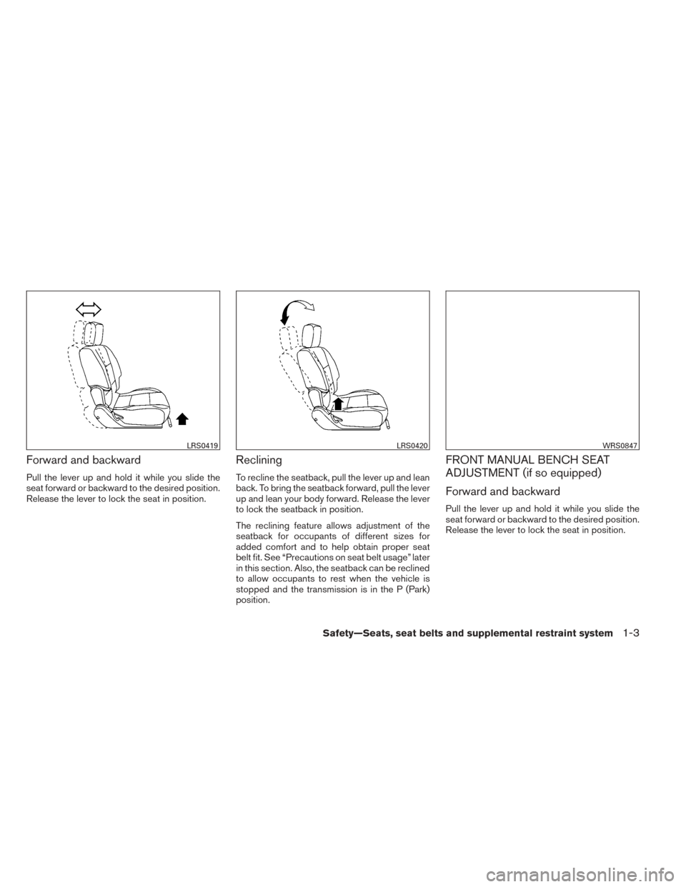
Forward and backward
Pull the lever up and hold it while you slide the
seat forward or backward to the desired position.
Release the lever to lock the seat in position.
Reclining
To recline the seatback, pull the lever up and lean
back. To bring the seatback forward, pull the lever
up and lean your body forward. Release the lever
to lock the seatback in position.
The reclining feature allows adjustment of the
seatback for occupants of different sizes for
added comfort and to help obtain proper seat
belt fit. See “Precautions on seat belt usage” later
in this section. Also, the seatback can be reclined
to allow occupants to rest when the vehicle is
stopped and the transmission is in the P (Park)
position.
FRONT MANUAL BENCH SEAT
ADJUSTMENT (if so equipped)
Forward and backward
Pull the lever up and hold it while you slide the
seat forward or backward to the desired position.
Release the lever to lock the seat in position.
LRS0419LRS0420WRS0847
Safety—Seats, seat belts and supplemental restraint system1-3
Page 21 of 455
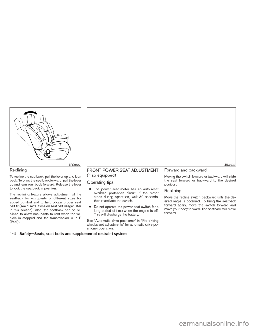
Reclining
To recline the seatback, pull the lever up and lean
back. To bring the seatback forward, pull the lever
up and lean your body forward. Release the lever
to lock the seatback in position.
The reclining feature allows adjustment of the
seatback for occupants of different sizes for
added comfort and to help obtain proper seat
belt fit (see “Precautions on seat belt usage” later
in this section) . Also, the seatback can be re-
clined to allow occupants to rest when the ve-
hicle is stopped and the transmission is in P
(Park) .
FRONT POWER SEAT ADJUSTMENT
(if so equipped)
Operating tips
●The power seat motor has an auto-reset
overload protection circuit. If the motor
stops during operation, wait 30 seconds,
then reactivate the switch.
● Do not operate the power seat switch for a
long period of time when the engine is off.
This will discharge the battery.
See “Automatic drive positioner” in “Pre-driving
checks and adjustments” for automatic drive po-
sitioner operation.
Forward and backward
Moving the switch forward or backward will slide
the seat forward or backward to the desired
position.
Reclining
Move the recline switch backward until the de-
sired angle is obtained. To bring the seatback
forward again, move the switch forward and
move your body forward. The seatback will move
forward.
LRS0427LRS0633
1-4Safety—Seats, seat belts and supplemental restraint system
Page 81 of 455
2 Instruments and controls
Instrument panel...................................2-2
Meters and gauges ................................2-4
Speedometer and odometer . . ...................2-5
Tachometer ....................................2-6
Engine coolant temperature gauge ...............2-6
Fuel gauge ....................................2-7
Engine oil pressure gauge (if so equipped) ........2-7
Voltmeter (if so equipped) .......................2-8
Automatic transmission fluid temperature
gauge (if so equipped) ..........................2-8
Compass display (if so equipped) ...................2-9
Compass display .............................. 2-10
Warning/indicator lights and audible reminders ......2-13
Checking bulbs ............................... 2-13
Warning lights ................................ 2-13
Indicator lights ................................ 2-18
Audible reminders ............................. 2-20
Vehicle Information Display (if so equipped) .........2-21
How to use the Vehicle Information Display .......2-21
Security systems (if so equipped) ..................2-25
Vehicle security system (if so equipped) ..........2-25
NISSAN vehicle immobilizer system
(if so equipped) ............................... 2-26Windshield wiper and washer switch
...............2-27
Switch operation .............................. 2-27
Rear window and outside mirror (if so equipped)
defroster switch .................................. 2-28
Headlight and turn signal switch ....................2-30
Headlight control switch ........................ 2-30
Daytime running light system (Canada only) ......2-32
Instrument brightness control ...................2-33
Turn signal switch ............................. 2-33
Fog light switch (if so equipped) ................2-33
Horn ............................................ 2-34
Cargo lamp switch (if so equipped) .................2-34
Heated seats (if so equipped) ......................2-34
Vehicle Dynamic Control (VDC) off switch ...........2-36
Electronic locking rear differential (E-Lock) system
switch (if so equipped) ............................ 2-36
Power inverter switch (if so equipped) ..............2-37
Rear
sonar system off switch (if so equipped) ........2-38
Tow mode switch ................................. 2-38
Power outlets .................................... 2-39
12v Outlets ................................... 2-39
120v outlet (if so equipped) ....................2-40
Storage ......................................... 2-42
Page 85 of 455
1. Warning/indicator lights
2. Tachometer
3. Engine coolant temperature gauge
4. Voltmeter (if so equipped)
5. Fuel gauge
6. Speedometer7. Automatic transmission fluid tempera-
ture gauge (if so equipped)
8. Odometer/Twin trip odometer/Vehicle
Information Display
9. Engine oil pressure gauge
(if so equipped)
WIC1243
METERS AND GAUGES
2-4Instruments and controls
Page 89 of 455
CAUTION
●This gauge is not designed to indicate
low engine oil level. Use the dipstick to
check the oil level. (See “Engine oil” in
the “Maintenance and do-it-yourself”
section.)
● If the gauge needle does not move with
the proper amount of engine oil, have
the vehicle checked by a NISSAN
dealer. Continued vehicle operation in
such a condition could cause serious
damage to the engine.
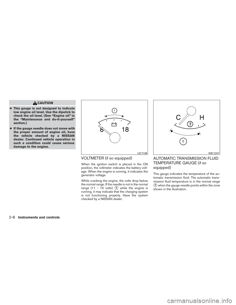
VOLTMETER (if so equipped)
When the ignition switch is placed in the ON
position, the voltmeter indicates the battery volt-
age. When the engine is running, it indicates the
generator voltage.
While cranking the engine, the volts drop below
the normal range. If the needle is not in the normal
range (11 - 15 volts)
�1while the engine is
running, it may indicate that the charging system
is not functioning properly. Have the system
checked by a NISSAN dealer.
AUTOMATIC TRANSMISSION FLUID
TEMPERATURE GAUGE (if so
equipped)
This gauge indicates the temperature of the au-
tomatic transmission fluid. The automatic trans-
mission fluid temperature is in the normal range
�1when the gauge needle points within the zone
shown in the illustration.
LIC1136WIC1247
2-8Instruments and controls
Page 90 of 455
CAUTION
●This gauge is not designed to indicate
low automatic transmission fluid level.
Use the dipstick to check the fluid level.
(See “5-speed automatic transmission
fluid” in the “Maintenance and do-it-
yourself” section.)
● If the gauge indicates automatic trans-
mission fluid temperature over the nor-
mal range, stop the vehicle as soon as
safely possible. Have the vehicle
checked by a NISSAN dealer. Contin-
ued operation of the vehicle may seri-
ously damage the transmission. This unit measures terrestrial magnetism and in-
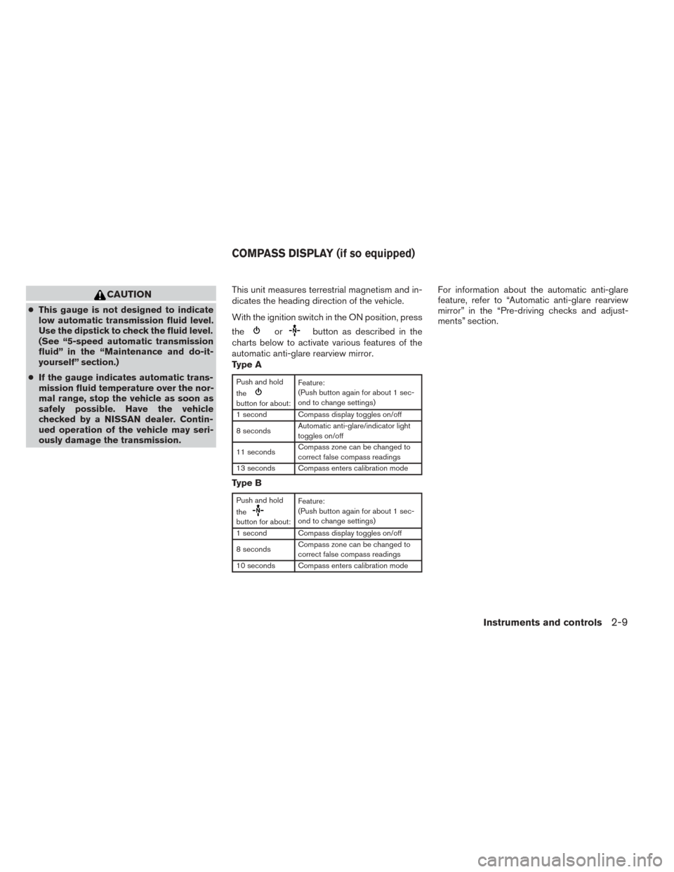
dicates the heading direction of the vehicle.
With the ignition switch in the ON position, press
the
orbutton as described in the
charts below to activate various features of the
automatic anti-glare rearview mirror.
Type A
Push and hold
the
button for about: Feature:
(Push button again for about 1 sec-
ond to change settings)
1 second Compass display toggles on/off
8 seconds Automatic anti-glare/indicator light
toggles on/off
11 seconds Compass zone can be changed to
correct false compass readings
13 seconds Compass enters calibration mode
Type B
Push and hold
the
button for about: Feature:
(Push button again for about 1 sec-
ond to change settings)
1 second Compass display toggles on/off
8 seconds Compass zone can be changed to
correct false compass readings
10 seconds Compass enters calibration mode
For information about the automatic anti-glare
feature, refer to “Automatic anti-glare rearview
mirror” in the “Pre-driving checks and adjust-
ments” section.
COMPASS DISPLAY (if so equipped)
Instruments and controls2-9
Page 94 of 455
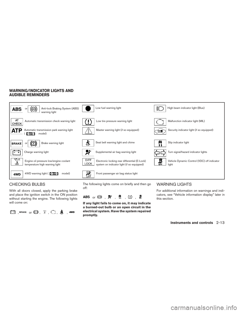
orAnti-lock Braking System (ABS)
warning lightLow fuel warning lightHigh beam indicator light (Blue)
Automatic transmission check warning lightLow tire pressure warning lightMalfunction indicator light (MIL)
Automatic transmission park warning light
(model)Master warning light (if so equipped)Security indicator light (if so equipped)
orBrake warning lightSeat belt warning light and chimeSlip indicator light
Charge warning lightSupplemental air bag warning lightTurn signal/hazard indicator lights
Engine oil pressure low/engine coolant
temperature high warning lightElectronic locking rear differential (E-Lock)
system on indicator light (if so equipped)Vehicle Dynamic Control (VDC) off indicator
light
4WD warning light (model)Front passenger air bag status light
CHECKING BULBS
With all doors closed, apply the parking brake
and place the ignition switch in the ON position
without starting the engine. The following lights
will come on:
,or,,,,
The following lights come on briefly and then go
off:
or,,,,
If any light fails to come on, it may indicate
a burned-out bulb or an open circuit in the
electrical system. Have the system repaired
promptly.
WARNING LIGHTS
For additional information on warnings and indi-
cators, see “Vehicle information display” later in
this section.
WARNING/INDICATOR LIGHTS AND
AUDIBLE REMINDERS
Instruments and controls2-13