2014 NISSAN TEANA fuel cap
[x] Cancel search: fuel capPage 2485 of 4801
FUEL SYSTEMFL-5
< PERIODIC MAINTENANCE >
C
D E
F
G H
I
J
K L
M A
FL
NP
O
PERIODIC MAINTENANCE
FUEL SYSTEM
InspectionINFOID:0000000009460600
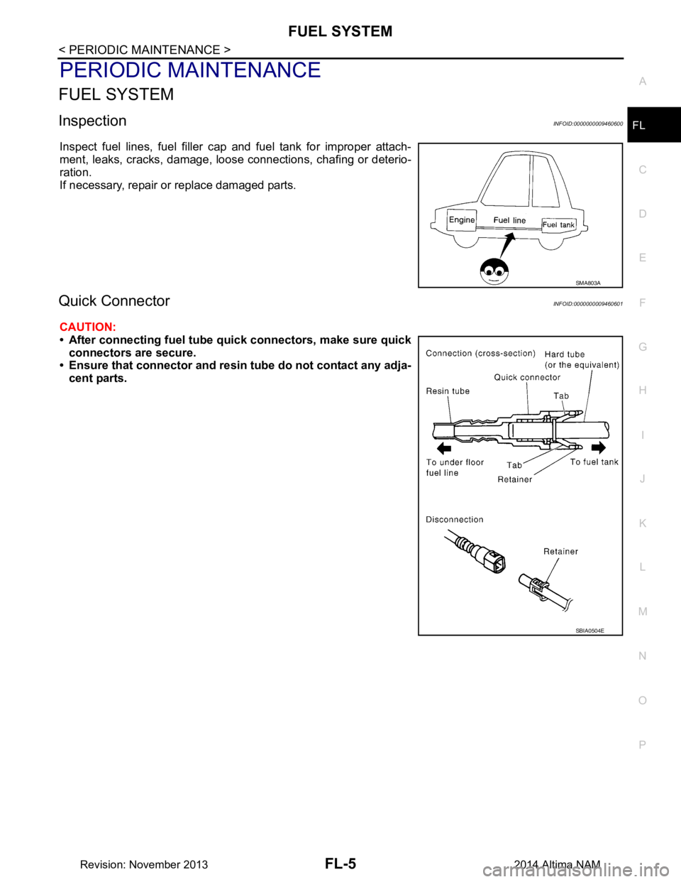
Inspect fuel lines, fuel filler cap and fuel tank for improper attach-
ment, leaks, cracks, damage, loos e connections, chafing or deterio-
ration.
If necessary, repair or replace damaged parts.
Quick ConnectorINFOID:0000000009460601
CAUTION:
• After connecting fuel tube qu ick connectors, make sure quick
connectors are secure.
• Ensure that connector and resin tube do not contact any adja-
cent parts.
SMA803A
SBIA0504E
Revision: November 20132014 Altima NAM
Page 2486 of 4801
FL-6
< REMOVAL AND INSTALLATION >
FUEL LEVEL SENSOR UNIT, FUEL FILTER AND FUEL PUMP ASSEMBLY
REMOVAL AND INSTALLATION
FUEL LEVEL SENSOR UNIT, FUEL FILTER AND FUEL PUMP ASSEMBLY
Exploded ViewINFOID:0000000009460602
Removal and InstallationINFOID:0000000009460603
REMOVAL
WARNING:
Read “General Precautions” before wo rking on the fuel system. Refer to FL-2, "General Precaution"
.
1. Disconnect the battery negative terminal. Refer to PG-73, "Removal and Installation (Battery)"
.
2. Unscrew the fuel filler cap to release the pressure inside the fuel tank.
3. Release the fuel pressure from the fuel lines. Refer to EC-182, "Work Procedure"
(QR25DE), EC-182,
"Work Procedure" (VQ35DE).
4. Remove the rear seat cushion. Refer to SE-36, "Removal and Installation - Seat Assembly"
.
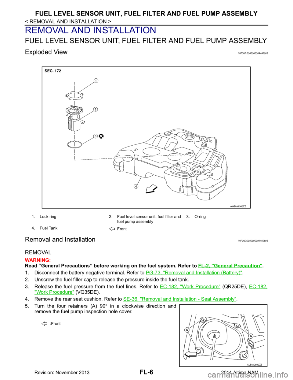
5. Turn the four retainers (A) 90 ° in a clockwise direction and
remove the fuel pump inspection hole cover.
1. Lock ring 2. Fuel level sensor unit, fuel filter and
fuel pump assembly3. O-ring
4. Fuel Tank Front
AWBIA1345ZZ
:Front
ALBIA0892ZZ
Revision: November 20132014 Altima NAM
Page 2490 of 4801
FL-10
< REMOVAL AND INSTALLATION >
FUEL TANK
FUEL TANK
Exploded ViewINFOID:0000000009460605
Removal and InstallationINFOID:0000000009460606
REMOVAL
WARNING:
Read “General Precautions” before wo rking on the fuel system. Refer to FL-2, "General Precaution"
.
NOTE:
When removing components such as hoses, tubes/lines, etc. , cap or plug openings to prevent fluid from spill-
ing.
1. Disconnect the battery negative terminal. Refer to PG-73, "Removal and Installation (Battery)"
.
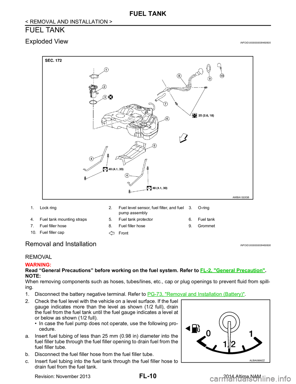
2. Check the fuel level with the vehicle on a level surface. If the fuel gauge indicates more than the level as shown (1/2 full), drain
the fuel from the fuel tank until the fuel gauge indicates a level at
or below as shown (1/2 full).
• In case the fuel pump does not operate, use the following pro- cedure.
a. Insert fuel tubing of less than 25 mm (0.98 in) diameter into the fuel filler tube through the fuel f iller opening to drain fuel from the
fuel filler tube.
b. Disconnect the fuel filler hose from the fuel filler tube.
c. Insert fuel tubing into the fuel tank through the fuel filler hose to drain fuel from the fuel tank.
1. Lock ring 2. Fuel level sensor, fuel filter, and fuel
pump assembly3. O-ring
4. Fuel tank mounting straps 5. Fuel tank protector 6. Fuel tank
7. Fuel filler hose 8. Fuel filler hose 9. Grommet
10. Fuel filler cap Front
AWBIA1322GB
ALBIA0898ZZ
Revision: November 20132014 Altima NAM
Page 2491 of 4801
FUEL TANKFL-11
< REMOVAL AND INSTALLATION >
C
D E
F
G H
I
J
K L
M A
FL
NP
O
• As a guide, if the fuel tank is full the fuel leve
l reaches or is less than the level on the fuel gauge as
shown, when approximately 34 (9 US gal, 7 1/2 Imp gal) of fuel is drained from a full fuel tank.
3. Open the fuel filler cap to release the pressure inside the fuel tank.
4. Release fuel pressure from fuel line. Refer to EC-182, "Work Procedure"
(QR25DE), EC-687, "Work Pro-
cedure" (VQ35DE).
5. Remove rear seat cushion. Refer to SE-36, "Removal and Installation - Seat Assembly"
.
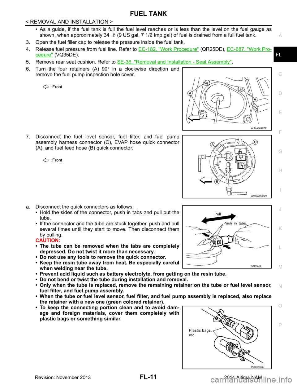
6. Turn the four retainers (A) 90 ° in a clockwise direction and
remove the fuel pump inspection hole cover.
7. Disconnect the fuel level sensor, fuel filter, and fuel pump assembly harness connector (C), EVAP hose quick connector
(A), and fuel feed hose (B) quick connector.
a. Disconnect the quick connectors as follows: • Hold the sides of the connector, push in tabs and pull out the
tube.
• If the connector and the tube are stuck together, push and pull
several times until they start to move. Then disconnect them
by pulling.
CAUTION:
• The tube can be removed when the tabs are completely depressed. Do not twist it more than necessary.
• Do not use any tools to remove the quick connector.
• Keep the resin tube away from heat. Be especially careful
when welding near the tube.
• Prevent acid liquid such as battery elect rolyte, from getting on the resin tube.
• Do not bend or twist the tube during installation and removal.
• Only when the tube is replaced, remove the remaining retainer on the tube or fuel level sensor,
fuel filter, and fuel pump assembly.
• When the tube or fuel level sen sor, fuel filter, and fuel pump assembly is replaced, also replace
the retainer with a new one (green colored retainer).
• To keep the connecting portio n clean and to avoid dam-
age and foreign materials, cover them completely with
plastic bags or something similar.
:Front
ALBIA0892ZZ
:Front
AWBIA1308ZZ
SFE562A
PBIC0163E
Revision: November 20132014 Altima NAM
Page 2501 of 4801
SERVICE DATA AND SPECIFICATIONS (SDS)FL-21
< SERVICE DATA AND SPECIFICATIONS (SDS)
C
D E
F
G H
I
J
K L
M A
FL
NP
O
SERVICE DATA AND SPECIFICATIONS (SDS)
SERVICE DATA AND SPECIFICATIONS (SDS)
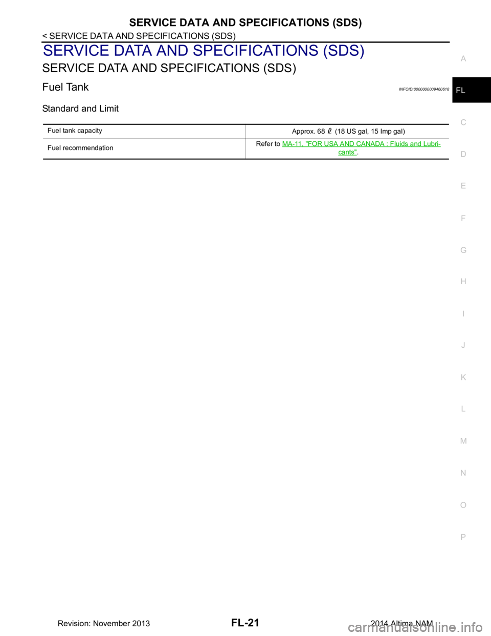
Fuel TankINFOID:0000000009460618
Standard and Limit
Fuel tank capacity
Approx. 68 (18 US gal, 15 Imp gal)
Fuel recommendation Refer to
MA-11, "FOR USA AND CANADA : Fluids and Lubri-
cants".
Revision: November 20132014 Altima NAM
Page 2508 of 4801
FRONT SUSPENSION ASSEMBLYFSU-7
< PERIODIC MAINTENANCE >
C
D
F
G H
I
J
K L
M A
B
FSU
N
O P
PERIODIC MAINTENANCE
FRONT SUSPENSION ASSEMBLY
Inspection and AdjustmentINFOID:0000000009460626
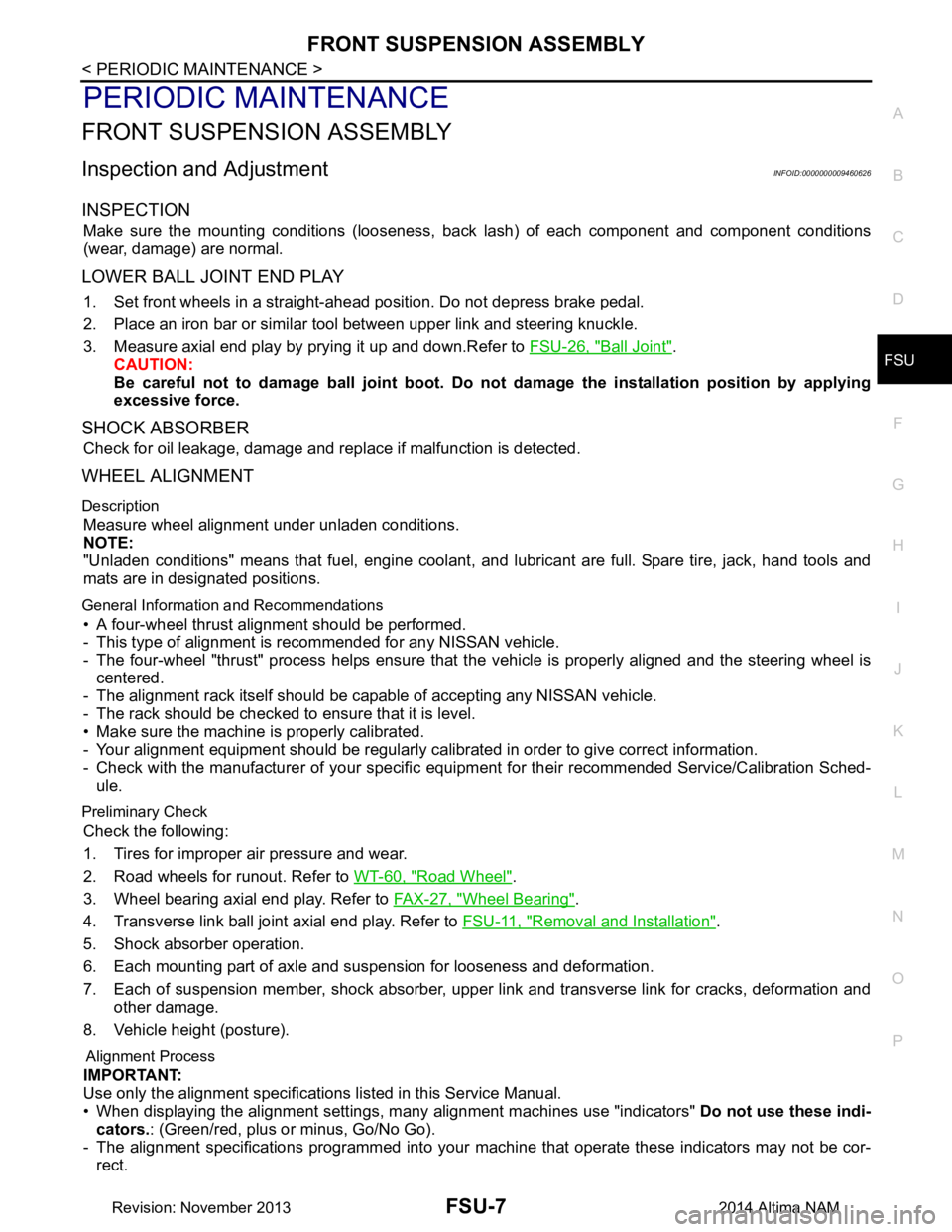
INSPECTION
Make sure the mounting conditions (looseness, back lash) of each component and component conditions
(wear, damage) are normal.
LOWER BALL JOINT END PLAY
1. Set front wheels in a straight-ahead position. Do not depress brake pedal.
2. Place an iron bar or similar tool between upper link and steering knuckle.
3. Measure axial end play by prying it up and down.Refer to FSU-26, "Ball Joint"
.
CAUTION:
Be careful not to damage ball joint boot. Do not damage the installation position by applying
excessive force.
SHOCK ABSORBER
Check for oil leakage, damage and repl ace if malfunction is detected.
WHEEL ALIGNMENT
Description
Measure wheel alignment under unladen conditions.
NOTE:
"Unladen conditions" means that fuel, engine coolant, and lubricant are full. Spare tire, jack, hand tools and
mats are in designated positions.
General Information and Recommendations
• A four-wheel thrust alignment should be performed.
- This type of alignment is re commended for any NISSAN vehicle.
- The four-wheel "thrust" process helps ensure that t he vehicle is properly aligned and the steering wheel is
centered.
- The alignment rack itself should be capable of accepting any NISSAN vehicle.
- The rack should be checked to ensure that it is level.
• Make sure the machine is properly calibrated.
- Your alignment equipment should be regularly ca librated in order to give correct information.
- Check with the manufacturer of your specific equi pment for their recommended Service/Calibration Sched-
ule.
Preliminary Check
Check the following:
1. Tires for improper air pressure and wear.
2. Road wheels for runout. Refer to WT-60, "Road Wheel"
.
3. Wheel bearing axial end play. Refer to FAX-27, "Wheel Bearing"
.
4. Transverse link ball joint axial end play. Refer to FSU-11, "Removal and Installation"
.
5. Shock absorber operation.
6. Each mounting part of axle and suspension for looseness and deformation.
7. Each of suspension member, shock absorber, upper link and transverse link for cracks, deformation and other damage.
8. Vehicle height (posture).
Alignment Process
IMPORTANT:
Use only the alignment specificati ons listed in this Service Manual.
• When displaying the alignment settings, m any alignment machines use "indicators" Do not use these indi-
cators. : (Green/red, plus or minus, Go/No Go).
- The alignment specifications programmed into your machine that operate these indicators may not be cor-
rect.
Revision: November 20132014 Altima NAM
Page 2556 of 4801
GI-28
< PRECAUTION >
PRECAUTIONS
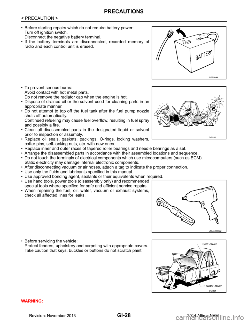
• Before starting repairs which do not require battery power:Turn off ignition switch.
Disconnect the negative battery terminal.
• If the battery terminals are disconnected, recorded memory of
radio and each control unit is erased.
• To prevent serious burns: Avoid contact with hot metal parts.
Do not remove the radiator cap when the engine is hot.
• Dispose of drained oil or the solvent used for cleaning parts in an
appropriate manner.
• Do not attempt to top off the fuel tank after the fuel pump nozzle
shuts off automatically.
Continued refueling may cause fuel overflow, resulting in fuel spray
and possibly a fire.
• Clean all disassembled parts in the designated liquid or solvent
prior to inspection or assembly.
• Replace oil seals, gaskets, packings, O-rings, locking washers, cotter pins, self-locking nuts, etc. with new ones.
• Replace inner and outer races of tapered roller bearings and needle bearings as a set.
• Arrange the disassembled parts in accordance with their assembled locations and sequence.
• Do not touch the terminals of electrical com ponents which use microcomputers (such as ECM).
Static electricity may damage internal electronic components.
• After disconnecting vacuum or air hoses, atta ch a tag to indicate the proper connection.
• Use only the fluids and lubricants specified in this manual.
• Use approved bonding agent, sealants or their equivalents when required.
• Use hand tools, power tools (disassembly only) and recommended special tools where specified for safe and efficient service repairs.
• When repairing the fuel, oil, water, vacuum or exhaust systems,
check all affected lines for leaks.
• Before servicing the vehicle: Protect fenders, upholstery and carpeting with appropriate covers.
Take caution that keys, buckles or buttons do not scratch paint.
WARNING:
SEF289H
SGI233
JPAIA0335ZZ
SGI234
Revision: November 20132014 Altima NAMRevision: November 20132014 Altima NAM
Page 2982 of 4801
![NISSAN TEANA 2014 Service Manual
LAN
SYSTEMLAN-33
< SYSTEM DESCRIPTION > [CAN]
C
D E
F
G H
I
J
K L
B
A
O P
N
Engine status signal T R R R R
Fuel consumption monitor signal T R R
Fuel filler cap warning display signal T R
Malfunc NISSAN TEANA 2014 Service Manual
LAN
SYSTEMLAN-33
< SYSTEM DESCRIPTION > [CAN]
C
D E
F
G H
I
J
K L
B
A
O P
N
Engine status signal T R R R R
Fuel consumption monitor signal T R R
Fuel filler cap warning display signal T R
Malfunc](/manual-img/5/57390/w960_57390-2981.png)
LAN
SYSTEMLAN-33
< SYSTEM DESCRIPTION > [CAN]
C
D E
F
G H
I
J
K L
B
A
O P
N
Engine status signal T R R R R
Fuel consumption monitor signal T R R
Fuel filler cap warning display signal T R
Malfunctioning indicator lamp signal TR
RT
Oil pressure warning lamp signal T R
Power generation command value
signal TR
Target throttle position signal T R
Wide open throttle position signal T R
EPS operation signal R T
Hydraulic pump electric power steer-
ing warning lamp signal TR
Detention switch signal T R R
Front wiper stop position signal T R
High beam status signal R T
Hood switch signal T R
Interlock/PNP switch signal RT
TR R
Low beam status signal R T
Oil pressure switch signal RT
TR R
Push-button ignition switch status
signal TR
Rear window defogger control signal R T
Sleep ready signal T R
Starter relay status signal T R
Steering lock unit status signal T R
Steering lock relay signal RT
TR
Current gear position signal T R R
CVT position indicator signal T R R
Input shaft revolution signal R T R R
Manual mode indicator signal T R R
N range signal T R
Output shaft revolution signal R T R R
O/D OFF indicator signal
*1TR R
P range signal T R R
Shift position signal T R R
Brake fluid level signal T R
Distance to empty signal T R
Fuel filler cap warning reset signal R T
Fuel level low warning signal T R
Fuel level sensor signal R T Signal name
ECM
EPS
IPDM-E TCM
M&A
STRG AV
AV M
HVAC ABS
BCM
Revision: November 20132014 Altima NAMRevision: November 20132014 Altima NAM