2014 NISSAN TEANA change wheel
[x] Cancel search: change wheelPage 1338 of 4801
![NISSAN TEANA 2014 Service Manual
EC-338
< DTC/CIRCUIT DIAGNOSIS >[QR25DE]
P0441 EVAP CONTROL SYSTEM
2.PERFORM DTC CONFIRMATION PROCEDURE-1
WITH CONSULT
TESTING CONDITION:
Always perform test at a temperature of 5 °C (41 °F) or mo NISSAN TEANA 2014 Service Manual
EC-338
< DTC/CIRCUIT DIAGNOSIS >[QR25DE]
P0441 EVAP CONTROL SYSTEM
2.PERFORM DTC CONFIRMATION PROCEDURE-1
WITH CONSULT
TESTING CONDITION:
Always perform test at a temperature of 5 °C (41 °F) or mo](/manual-img/5/57390/w960_57390-1337.png)
EC-338
< DTC/CIRCUIT DIAGNOSIS >[QR25DE]
P0441 EVAP CONTROL SYSTEM
2.PERFORM DTC CONFIRMATION PROCEDURE-1
WITH CONSULT
TESTING CONDITION:
Always perform test at a temperature of 5 °C (41 °F) or more.
1. Start engine and warm it up to normal operating temperature.
2. Turn ignition switch OFF and wait at least 10 seconds.
3. Turn ignition switch ON.
4. Turn ignition switch OFF and wait at least 10 seconds.
5. Start engine and let it idle for at least 70 seconds.
6. Select “PURG FLOW P0441” of “EVAPORATI VE SYSTEM” in “DTC WORK SUPPORT” mode of
“ENGINE” using CONSULT.
7. Touch “START”.
Is
“COMPLETED” displayed on CONSULT screen?
YES >> GO TO 4.
NO >> GO TO 3.
3.PERFORM DTC CONFIRMATION PROCEDURE-2
When the following conditions are met, “TESTING” will be displayed on the CONSULT screen. Maintain the
conditions continuously until “TESTING” changes to “COMPLETED”. (It will take at least 35 seconds.)
CAUTION:
Always drive vehicle at a safe speed.
NOTE:
If “TESTING” does not change for a long time, retry from step 2.
Is
“COMPLETED” displayed on CONSULT screen?
YES >> GO TO 4.
NO >> Perform DTC CONFIRMATION PROCEDURE again. GO TO 2.
4.PERFORM DTC CONFIRMATION PROCEDURE-3
Touch “SELF-DIAG RESULTS”.
Which is displayed on CONSULT screen?
OK >> INSPECTION END
NG >> Proceed to EC-339, "Diagnosis Procedure"
.
5.PERFORM COMPONENT FUNCTION CHECK
WITH GST
Perform component function check. Refer to EC-338, "Component Function Check"
.
NOTE:
Use component function check to check the overall moni toring function of the EVAP control system purge flow
monitoring. During this check, a 1st trip DTC might not be confirmed.
Is the inspection result normal?
YES >> INSPECTION END
NO >> Proceed to EC-339, "Diagnosis Procedure"
.
Component Function CheckINFOID:0000000009462270
1.PERFORM COMPONENT FUNCTION CHECK
1. Lift up drive wheels.
2. Start engine (VDC switch OFF) and warm it up to normal operating temperature.
3. Turn ignition switch OFF and wait at least 10 seconds.
Selector lever Suitable position
VHCL SPEED SE 32 - 120 km/h (20 - 75 MPH)
ENG SPEED 500 - 3,800 rpm
B/FUEL SCHDL 1.0 - 10.0 msec
COOLAN TEMP/S More than 0 °C (32 °F)
Revision: November 20132014 Altima NAMRevision: November 20132014 Altima NAM
Page 3189 of 4801

GENERAL MAINTENANCEMA-5
< PERIODIC MAINTENANCE >
C
D E
F
G H
I
J
K L
M B
MA
N
O A
PERIODIC MAINTENANCE
GENERAL MAINTENANCE
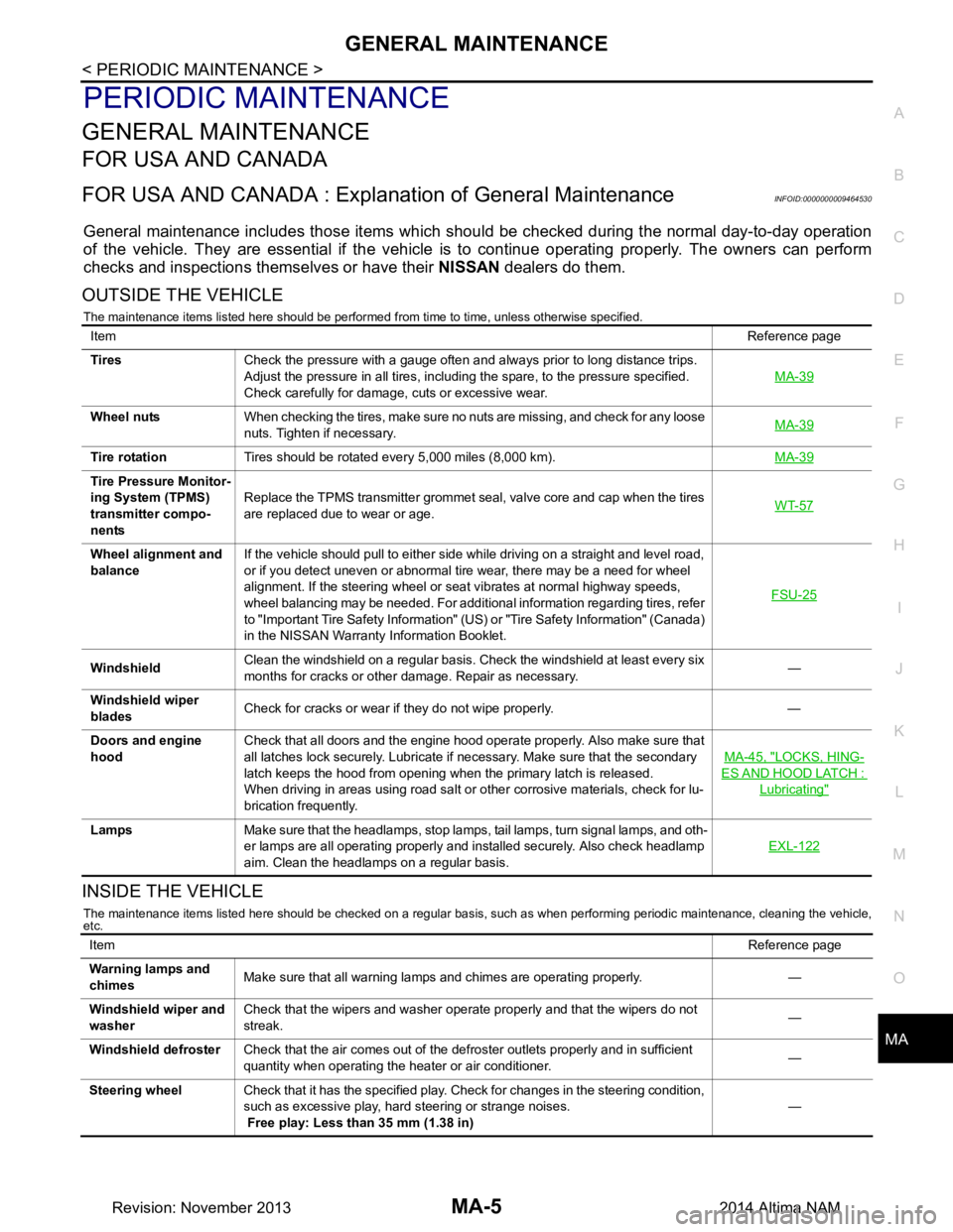
FOR USA AND CANADA
FOR USA AND CANADA : Explana
tion of General MaintenanceINFOID:0000000009464530
General maintenance includes those items which shoul d be checked during the normal day-to-day operation
of the vehicle. They are essential if the vehicle is to continue operating properly. The owners can perform
checks and inspections themselves or have their NISSAN dealers do them.
OUTSIDE THE VEHICLE
The maintenance items listed here should be performed from time to time, unless otherwise specified.
INSIDE THE VEHICLE
The maintenance items listed here should be checked on a regular basis, such as when performing periodic maintenance, cleaning the vehicle,
etc.
Item Reference page
Tires Check the pressure with a gauge often and always prior to long distance trips.
Adjust the pressure in all tires, including the spare, to the pressure specified.
Check carefully for damage, cuts or excessive wear. MA-39
Wheel nuts
When checking the tires, make sure no nuts are missing, and check for any loose
nuts. Tighten if necessary. MA-39
Tire rotation
Tires should be rotated every 5,000 miles (8,000 km). MA-39
Tire Pressure Monitor-
ing System (TPMS)
transmitter compo-
nents Replace the TPMS transmitter grommet seal, valve core and cap when the tires
are replaced due to wear or age. WT-57
Wheel alignment and
balance If the vehicle should pull to either side while driving on a straight and level road,
or if you detect uneven or abnormal tire wear, there may be a need for wheel
alignment. If the steering wheel or seat vibrates at normal highway speeds,
wheel balancing may be needed. For additional information regarding tires, refer
to "Important Tire Safety Information" (US) or "Tire Safety Information" (Canada)
in the NISSAN Warranty Information Booklet. FSU-25
Windshield
Clean the windshield on a regular basis. Check the windshield at least every six
months for cracks or other damage. Repair as necessary. —
Windshield wiper
blades Check for cracks or wear if they do not wipe properly. —
Doors and engine
hood Check that all doors and the engine hood operate properly. Also make sure that
all latches lock securely. Lubricate if necessary. Make sure that the secondary
latch keeps the hood from opening when the primary latch is released.
When driving in areas using road salt or other corrosive materials, check for lu-
brication frequently. MA-45, "LOCKS, HING-
ES AND HOOD LATCH :
Lubricating"
Lamps
Make sure that the headlamps, stop lamps, tail lamps, turn signal lamps, and oth-
er lamps are all operating properly and installed securely. Also check headlamp
aim. Clean the headlamps on a regular basis. EXL-122
Item
Reference page
Warning lamps and
chimes Make sure that all warning lamps and chimes are operating properly. —
Windshield wiper and
washer Check that the wipers and washer operate properly and that the wipers do not
streak. —
Windshield defroster Check that the air comes out of the defroster outlets properly and in sufficient
quantity when operating the heater or air conditioner. —
Steering wheel Check that it has the specified play. Check for changes in the steering condition,
such as excessive play, hard steering or strange noises.
Free play: Less than 35 mm (1.38 in) —
Revision: November 20132014 Altima NAM
Page 3325 of 4801

MWI-70
< DTC/CIRCUIT DIAGNOSIS >
STEERING SWITCH
STEERING SWITCH
DescriptionINFOID:0000000009461735
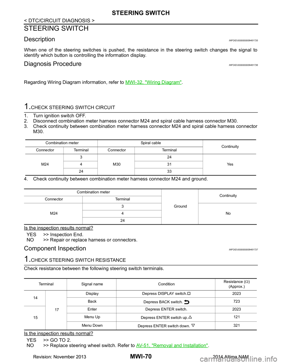
When one of the steering switches is pushed, the resistance in the steering switch changes the signal to
identify which button is controlling the information display.
Diagnosis ProcedureINFOID:0000000009461736
Regarding Wiring Diagram information, refer to MWI-32, "Wiring Diagram".
1.CHECK STEERING SWITCH CIRCUIT
1. Turn ignition switch OFF.
2. Disconnect combination meter harness connector M24 and spiral cable harness connector M30.
3. Check continuity between combination meter har ness connector M24 and spiral cable harness connector
M30.
4. Check continuity between combination meter harness connector M24 and ground.
Is the inspection results normal?
YES >> Inspection End.
NO >> Repair or replace harness or connectors.
Component InspectionINFOID:0000000009461737
1.CHECK STEERING SWITCH RESISTANCE
Check resistance between the following steering switch terminals.
Is the inspection results normal?
YES >> GO TO 2.
NO >> Replace steering wheel switch. Refer to AV-51, "Removal and Installation"
.
Combination meter Spiral cable
Continuity
Connector Terminal Connector Terminal
M24 3
M30 24
Ye s
431
24 33
Combination meter GroundContinuity
Connector Terminal
M24 3
No
4
24
Terminal Signal name Condition Resistance (
Ω)
(Approx.)
14
17 Display Depress DISPLAY switch.
�†2023
Back Depress BACK switch. 723
15 Enter Depress ENTER switch. 2023
Menu Up Depress ENTER switch up. 121
Menu Down Depress ENTER switch down. 321
Revision: November 20132014 Altima NAMRevision: November 20132014 Altima NAM
Page 3724 of 4801

REAR SUSPENSION ASSEMBLYRSU-7
< PERIODIC MAINTENANCE >
C
D
F
G H
I
J
K L
M A
B
RSU
N
O P
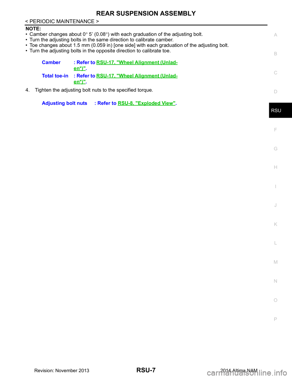
NOTE:
• Camber changes about 0 ° 5’ (0.08 °) with each graduation of the adjusting bolt.
• Turn the adjusting bolts in the same direction to calibrate camber.
• Toe changes about 1.5 mm (0.059 in) [one side] with each graduation of the adjusting bolt.
• Turn the adjusting bolts in the opposite direction to calibrate toe.
4. Tighten the adjusting bolt nuts to the specified torque. Camber : Refer to
RSU-17, "Wheel Alignment (Unlad-
en*)".
Total toe-in : Refer to RSU-17, "Wheel Alignment (Unlad-
en*)".
Adjusting bolt nuts : Refer to RSU-8, "Exploded View"
.
Revision: November 20132014 Altima NAM
Page 4160 of 4801

SYSTEMSTC-9
< SYSTEM DESCRIPTION >
C
D E
F
H I
J
K L
M A
B
STC
N
O P
HYDRAULIC PUMP ELECTRIC POWER STEE RING SYSTEM : Protection Function
INFOID:0000000009460346
• When the steering wheel is operated repeatedly or turned all the way for a long period during parking or low
speed driving, the function of the hydraulic pump elec tric power steering system becomes limited to prevent
the system from overheating. Cont inued operation of the steering wheel will cause the hydraulic pump elec-
tric power steering system to stop and the hydraulic pum p electric power steering system warning lamp may
come ON. In this case, the steering wheel operation temporarily becomes hard. This is not a malfunction.
When the engine is turned OFF (ignition switch OFF) and steering operation is stopped for a while, the tem-
perature of the hydraulic pump electric power steer ing system decreases and the steering operation returns
to normal after restarting the engine.
• Then, the hydraulic pump electric power steering syste m warning lamp turns OFF. If the system is OFF
under the protection state, the hydraulic pump electr ic power steering system warning lamp turns ON to
warn that the system is in the manual steering state. (This is not a system malfunction.) In addition, the fol-
lowing DTC remains to distinguish from malfunction.
C1608 Manual steering state
U1000 Normal control
NOTE:
If the cause is in a different ECU, the state changes to fixed steering assist force.
DTC Fail-safe condition
DTC vehicle condition
C160A The system temporarily enters the manual steering state. (This is not a hydraulic pump electric
power steering system malfunction.)
Revision: November 20132014 Altima NAMRevision: November 20132014 Altima NAM
Page 4162 of 4801

POWER STEERING CONTROL MODULESTC-11
< ECU DIAGNOSIS INFORMATION >
C
D E
F
H I
J
K L
M A
B
STC
N
O P
ECU DIAGNOSIS INFORMATION
POWER STEERING CONTROL MODULE
Reference ValueINFOID:0000000009460348
VALUES ON THE DIAGNOSIS TOOL
*1: The value changes according to load of power steering motor.
*2: This is in close agreement with a motor speed command value. Although a quick steering operation may
cause disagreement, this is not a malfunction.
*3: Usually, 100% is displayed. An excessive steer ing operation gradually lowers the percentage. When left
standing, the percentage returns to 100%.
Monitor item Data monitor
Condition Display value
BATTERY VOLT Engine running Battery voltage (V)
STEERING ANGLE The steering wheel is not steered. Approx. 0.0 deg
The steering wheel is steered. Displays steering angle (deg)
STR ANG SPD The steering wheel is not steered. Approx. 0.0 deg/s
The steering wheel is steered. Displays steering angle speed (deg/s)
MOTOR CURRENT Engine running Steering wheel: Not steering (There is
no steering force) MAX approx. 10 A
*1
Steering wheel: Right or left turnDisplays consumption current of pow-
er steering control module (A)
MTR REV SPD COMM Engine running Steering wheel: Not steering (There is
no steering force) Shows an almost constant value
(rpm)
Steering wheel: Right or left turn The value changes as a steering
speed (rpm)
MTR REV SPD Engine running Steering wheel: Not steering (There is
no steering force) Shows an almost constant value
(rpm)
*2
Steering wheel: Right or left turn The value changes as a steering
speed (rpm)*2
C/U TEMP Engine running Displays temperature of inside of
power steering control module ( °C or
° F)
C/U TEMP A Engine running Displays temperature of inside of
power steering control module ( °C or
° F)
MTR ASSIST Engine running 100%
*3
ESTM VHCL SPDVehicle stopped 0.00 km/h or mph
While driving Approximately equal to the indication
on speedometer*4
(inside of ±10%)
WARNING LAMP Hydraulic pump electric power steering warning lamp: ON On
Hydraulic pump electric power steering warning lamp: OFF Off
ENGINE STATUS Engine not running STOP
Engine running RUN
Engine cranking CRANK
VHCL SPD JUDGE Vehicle speed signal can be received via CAN communication OK
Vehicle speed signal cannot be received via CAN communica-
tion NG
Revision: November 20132014 Altima NAMRevision: November 20132014 Altima NAM
Page 4163 of 4801

STC-12
< ECU DIAGNOSIS INFORMATION >
POWER STEERING CONTROL MODULE
*4: This may not agree with the speedometer indication immediately after the ignition switch is turned ON. This
is not a malfunction.
TERMINAL LAYOUT
PHYSICAL VALUES
Fail-safeINFOID:0000000009460349
When an error occurs in the hydraulic pump electric pow er steering system, fail-safe brings the system to a
halt (manual steering) or restricted (constant steering assi st level) state. When the system is in a halt state,
fail-safe turns ON the hydraulic pump electric power steer ing warning lamp to warn the driver that the hydrau-
lic pump electric power steering system is in the manual steering state.
Protection FunctionINFOID:0000000009460350
• When the steering wheel is operated repeatedly or turned all the way for a long period during parking or low
speed driving, the function of the hydraulic pump elec tric power steering system becomes limited to prevent
the system from overheating. If the steering wheel is operated further more, the hydraulic pump electric
power steering system stops and the hydraulic pump el ectric power steering system warning lamp may be
turned ON. In this case, the steering wheel operation temporarily becomes hard. This is not a malfunction.
When the engine is turned OFF (ignition switch OFF) and steering operation is stopped for a while, the tem-
perature of the hydraulic pump electric power steeri ng system decreases and the steering operation returns
to normal after restarting the engine.
JSGIA0835ZZ
Te r m i n a l N o .
(Wire Color) Description
Condition Value
+ − Signal name Input/Output
1
(W) Ground Battery power supply Input Always Battery Voltage
2
(B) Ground Ground — Always 0 V
5
(BR) Ground Ignition power supply Input Ignition switch: ON Battery Voltage
Ignition switch: OFF 0 V
7
(P) — CAN-L Input/Output — —
8
(L) — CAN-H Input/Output — —
DTC Fail-safe condition
C1143 Certain steering assist force
C1601 Manual steering state
C1606 Manual steering state
C1607 Certain steering assist force
C1608 Manual steering state
U1000 Normal control
NOTE:
If the cause is in a different ECU, the state changes to fixed steering assist force.
Revision: November 20132014 Altima NAMRevision: November 20132014 Altima NAM
Page 4249 of 4801
![NISSAN TEANA 2014 Service Manual
TM-34
< SYSTEM DESCRIPTION >[CVT: RE0F10D]
SYSTEM
CVT CONTROL SYSTEM : Protection Control
INFOID:0000000009463989
The TCM becomes the protection control status temporar ily to protect the safety wh NISSAN TEANA 2014 Service Manual
TM-34
< SYSTEM DESCRIPTION >[CVT: RE0F10D]
SYSTEM
CVT CONTROL SYSTEM : Protection Control
INFOID:0000000009463989
The TCM becomes the protection control status temporar ily to protect the safety wh](/manual-img/5/57390/w960_57390-4248.png)
TM-34
< SYSTEM DESCRIPTION >[CVT: RE0F10D]
SYSTEM
CVT CONTROL SYSTEM : Protection Control
INFOID:0000000009463989
The TCM becomes the protection control status temporar ily to protect the safety when the safety of TCM and
transmission is lost. It automatically returns to the normal status if the safety is secured.
The TCM has the following protection control.
CONTROL FOR WHEEL SPIN
TORQUE IS REDUCED WHEN DRIVING WITH THE REVERSE GEAR
CONTROL WHEN FLUID TEMPERATURE IS HIGH
P2813 • Selector shock is large
•Start is slow
• Acceleration is slow
• Vehicle speed is not increased When a malfunction occurs on the low oil pressure side
• Selector shock is large When a malfunction occurs on the high oil pressure side
P2814 • Selector shock is large —
P2815 • Selector shock is large —
U0073 • Selector shock is large
•Start is slow
• Acceleration is slow
• Lock-up is not performed —
U0100 • Selector shock is large
•Start is slow
• Acceleration is slow
• Lock-up is not performed —
U0140 • Not changed from normal driving —
U0141 • Not changed from normal driving —
U0155 • Not changed from normal driving —
U0300 • Selector shock is large
•Start is slow
• Acceleration is slow
• Lock-up is not performed —
U1000 • Not changed from normal driving — U1117 • Not changed from normal driving — DTC Vehicle behavior Conditions of vehicle
Control
When a wheel spin is detected, the engine output and gear ratio are limited and the line pressure is increased.
Limits engine output when a wheel spin occurs in any of right and left drive wheels.
Vehicle behavior in
control If the accelerator is kept depressing during wheel spin, the engine revolution and vehicle speed are limited to
a certain degree.
Normal retu rn condi-
tion Wheel spin convergence returns the control to the normal control.
Control Engine output is controlled according to a vehicle speed while reversing the vehicle.
Vehicle behavior in
control Power performance may be lowered while reversing the vehicle.
Normal retu rn condi-
tion Torque returns to normal by positioning the selector lever in a range other than “R” position.
Control
When the CVT fluid temperature is high, the gear shift permission maximum revolution and the maximum
torque are reduced than usual to prevent increase of the oil temperature.
Vehicle behavior in
control Power performance may be lowered, compared to normal control.
Normal retu rn condi-
tion The control returns to the normal control when CVT fluid temperature is lowered.
Revision: November 20132014 Altima NAMRevision: November 20132014 Altima NAM