2014 NISSAN QASHQAI change wheel
[x] Cancel search: change wheelPage 204 of 338

the engine idling, and wait until the warning mes-
sage is no longer displayed, the 4WD mode re-
turns to the AUTO mode.
•Braking distance in 4WD mode is the same as in
2WD mode.
•Even if the mode automatically changes to AUTO
mode, when driving in the LOCK mode, the indi-
cator light stays in the LOCK mode.
CAUTION
•Only use the 4WD mode control when driving
in a straight direction (to select 2WD, AUTO or
LOCK).
•Do not use the 4WD mode control when turn-
ing or reversing.
•Do not use the 4WD mode control with the
front wheels spinning (to select 2WD, AUTO,
or LOCK).
•Be especially careful when starting or driving
on slippery surfaces with the 4WD mode set
to AUTO.
•Never drive on dry hard surface roads in the
LOCK position as this will overload the power
train and may cause serious malfunctions.
4WD MODE INDICATOR LIGHTS
•4WD mode indicator light (LOCK):
This light comes on when the ignition switch is
turned to the ON position, and turns off within 1
second. When selecting LOCK mode while theengine is running, this light will illuminate simul-
taneously along with the 4WD mode indicator
light (AUTO).
•4WD mode indicator light (AUTO):
This light comes on when the ignition switch is
turned to the ON position, and turns off within 1
second. If the engine is running, this light will illu-
minate when selecting AUTO mode.
The 4WD mode indicator light is located in the
instrument panel.
The light should turn off within 1 second of the
ignition switch being turned to the ON position.
While the engine is running, the 4WD mode indi-
cator light will display the position selected by
the 4WD mode control.
NOTE
The 4WD mode indicator light may blink while
shifting from one drive mode to another. Once
shifting is completed, the 4WD mode indicator
light will come on. If the indicator light does not
come on immediately, make sure that the area
around the vehicle is safe and free from ob-
stacles. Drive the vehicle straight (DO NOT ac-
celerate, decelerate or reverse), then turn the
4WD mode control.
If the 4WD warning lights comes on, the 4WD indi-
cator light(s) will go out.
DRIVING FOUR-WHEEL DRIVE (4WD)
SAFELY
Your NISSAN is designed for both normal and off-
road use. However, avoid driving in deep water or
mud as your NISSAN is mainly designed for leisure
use, unlike a conventional off-road vehicle.
Remember that Two-Wheel drive (2WD) models are
less capable than Four-Wheel Drive (4WD) models
for rough road driving and extrication when stuck,
for example, in deep snow or mud.
Please observe the following precautions:
•Drive carefully when off-road and avoid danger-
ous areas. Always wear seat belts to help keep
you and your passengers in position when driv-
ing over rough terrain.
•Do not drive across steep slopes. Instead drive
either straight up or straight down the slope. Off-
road vehicles can tip over sideways much more
easily than they can forwards or backwards.
•Many hills are too steep for any vehicle. If you
drive up them, you may stall. If you drive down
them, you may not be able to control your speed.
If you drive across them, you may roll over.
•Do not shift gears when driving on downhill
grades as this could cause loss of control of the
vehicle.
•Stay alert when driving to the top of a hill. At the
top there could be a drop-off or other hazard that
could cause an accident.
5-28Starting and driving
Page 207 of 338

mirrors) will illuminate. If the turn signal is then acti-
vated, the system chimes (twice) and the Blind spot
indicator light will start flashing bright orange to alert
you to the presence of vehicle(s) in the adjacent
lane.
The Blind spot indicator light continues to flash until
the detected vehicle(s) leave the detection zone.
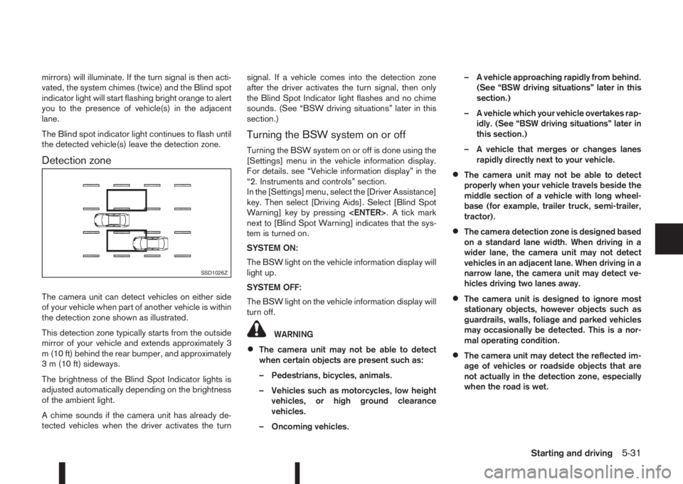
Detection zone
The camera unit can detect vehicles on either side
of your vehicle when part of another vehicle is within
the detection zone shown as illustrated.
This detection zone typically starts from the outside
mirror of your vehicle and extends approximately 3
m (10 ft) behind the rear bumper, and approximately
3 m (10 ft) sideways.
The brightness of the Blind Spot Indicator lights is
adjusted automatically depending on the brightness
of the ambient light.
A chime sounds if the camera unit has already de-
tected vehicles when the driver activates the turnsignal. If a vehicle comes into the detection zone
after the driver activates the turn signal, then only
the Blind Spot Indicator light flashes and no chime
sounds. (See “BSW driving situations” later in this
section.)
Turning the BSW system on or off
Turning the BSW system on or off is done using the
[Settings] menu in the vehicle information display.
For details. see “Vehicle information display” in the
“2. Instruments and controls” section.
In the [Settings] menu, select the [Driver Assistance]
key. Then select [Driving Aids]. Select [Blind Spot
Warning] key by pressing
next to [Blind Spot Warning] indicates that the sys-
tem is turned on.
SYSTEM ON:
The BSW light on the vehicle information display will
light up.
SYSTEM OFF:
The BSW light on the vehicle information display will
turn off.
WARNING
•The camera unit may not be able to detect
when certain objects are present such as:
– Pedestrians, bicycles, animals.
– Vehicles such as motorcycles, low height
vehicles, or high ground clearance
vehicles.
– Oncoming vehicles.– A vehicle approaching rapidly from behind.
(See “BSW driving situations” later in this
section.)
– A vehicle which your vehicle overtakes rap-
idly. (See “BSW driving situations” later in
this section.)
– A vehicle that merges or changes lanes
rapidly directly next to your vehicle.
•The camera unit may not be able to detect
properly when your vehicle travels beside the
middle section of a vehicle with long wheel-
base (for example, trailer truck, semi-trailer,
tractor).
•The camera detection zone is designed based
on a standard lane width. When driving in a
wider lane, the camera unit may not detect
vehicles in an adjacent lane. When driving in a
narrow lane, the camera unit may detect ve-
hicles driving two lanes away.
•The camera unit is designed to ignore most
stationary objects, however objects such as
guardrails, walls, foliage and parked vehicles
may occasionally be detected. This is a nor-
mal operating condition.
•The camera unit may detect the reflected im-
age of vehicles or roadside objects that are
not actually in the detection zone, especially
when the road is wet.
SSD1026Z
Starting and driving5-31
Page 215 of 338

•When additional floor mats are used, be sure
that they are correctly secured and that they
cannot interfere with the accelerator pedal.
Mats not adapted to the vehicle may prevent
proper operation of the speed limiter.
The speed limiter operation switches are located on
the steering wheel (right hand side).
The speed limiter operating condition is shown on
the top of vehicle information display. For details,
see “Vehicle information display” in the “2. Instru-
ments and controls” section.
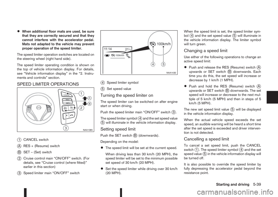
SPEED LIMITER OPERATIONS
j
1CANCEL switch
jARES + (Resume) switch
jBSET – (Set) switch
j2Cruise control main “ON/OFF” switch. (For
details, see “Cruise control (where fitted)”
earlier in this section)
j3Speed limiter main “ON/OFF” switch
j4Speed limiter symbol
j5Set speed value
Turning the speed limiter on
The speed limiter can be switched on after engine
start or when driving.
Push the speed limiter main “ON/OFF” switch
j3.
The speed limiter symbol
j4 and the set speed valuej5 will illuminate in the vehicle information display.
Setting speed limit
Push the SET switchjB (downwards).
Depending on the model:
•The speed limit will be set at the current speed.
When driving less than 30 km/h (20 MPH), the
speed limiter will be set to the minimum possible
set speed of 30 km/h (20 MPH).
•Set the speed limiter while driving over 30 km/h
(20 MPH).When the speed limit is set, the speed limiter sym-
bol
j4 and the set speed valuej5 will illuminate in
the vehicle information display. The limiter symbol
will turn green.
Changing a speed limit
Use either of the following operations to change an
active speed limit:
•Push and release the RES (Resume) switchjA
upwards or SET switchjB downwards. Each
time you do this, the set speed will increase or
decrease by 1 km/h (1 MPH).
•Push and hold the RES (Resume) switchjA
upwards or SET switchjB downwards. The set
speed will increase or decrease to the next mul-
tiple of 5 km/h (5 MPH) and then in steps of 5
km/h (5 MPH).
The new set speed limit value
j5 will be displayed
in the vehicle information display.
When the actual vehicle speed exceeds the set
speed, an audible warning will be heard a short time
after the set speed is exceeded and driver interven-
tion is not detected.
Cancelling a speed limit
To cancel a set speed limit, push the CANCEL
switchj1 . The speed limiter symbolj4 and the set
speed valuej5 in the vehicle information display will
be turned off.
It is also possible to override the speed limiter by
fully depressing the accelerator pedal beyond the
resistance point.
NAA1385
NAA1430
Starting and driving5-39
Page 222 of 338
![NISSAN QASHQAI 2014 Owner´s Manual Using the settings menu
The settings of the parking sensor system can be
changed.
At ignition on (the [Settings] menu is shown in the
display), select
[Driver Assistance] —> [Parking Aids]
or when t NISSAN QASHQAI 2014 Owner´s Manual Using the settings menu
The settings of the parking sensor system can be
changed.
At ignition on (the [Settings] menu is shown in the
display), select
[Driver Assistance] —> [Parking Aids]
or when t](/manual-img/5/40326/w960_40326-221.png)
Using the settings menu
The settings of the parking sensor system can be
changed.
At ignition on (the [Settings] menu is shown in the
display), select
[Driver Assistance] —> [Parking Aids]
or when the parking sensor screen is displayed,
press the
jB on the steering
wheel. Press the BACK switchjA to return to the
previous item.
The settings menu is shown
Set the following items on or off by selecting (high-
lighted) and pressing the
jB switch on
the steering wheel. When selected a green marker
is shown.
– [Front sensor]:
Switch the front sensors on or off
– [Rear sensor]:
Switch the rear sensors on or off– [Display]:
Switch the parking sensor system automatically
on or off when selecting R (Reverse) gear.
By highlighting the colour of the to be set item:
– Set the volume of the parking sensor system
Select [Volume] and press
•High
•Med.
•Low
– Set the range sensitivity
Select [Range] and press
•Far
•Mid.
•Near
WARNING
Intelligent Parking Assist (IPA) is a guidance sys-
tem for parking procedures. It does not prevent
collisions with objects. Always look through the
windows and check to be sure that it is safe to
move.
The Intelligent Parking Assist (IPA) system controls
steering, guiding the vehicle when parking:
– In a bay
– Parallel to the road
NOTE
The IPA system instructs you to stop, drive for-
wards or drive backwards. Follow the instructions
given by the system.
The IPA system is not able to support parking when
the vehicle speed during the parking manoeuvre is
more than 7 km/h (4 MPH).
CAUTION
Do not use the IPA system under the following
conditions:
•On unpaved roads.
•On snow-covered or frozen roads.
•On uneven roads with slants, bumps, kerb-
stones, wheel tracks, etc.
•At mechanical parking facilities.
•When tyre chains or a spare tyre are installed.
NIC2204
INTELLIGENT PARKING ASSIST
(IPA) (where fitted)
5-46Starting and driving
Page 229 of 338

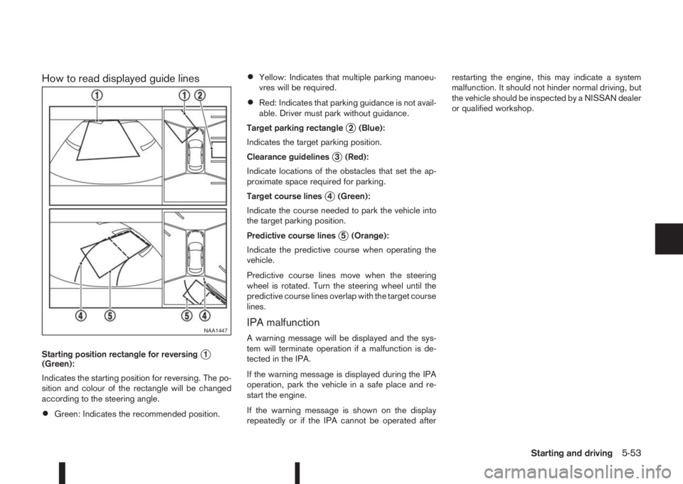
How to read displayed guide lines
Starting position rectangle for reversingj1
(Green):
Indicates the starting position for reversing. The po-
sition and colour of the rectangle will be changed
according to the steering angle.
•Green: Indicates the recommended position.
•Yellow: Indicates that multiple parking manoeu-
vres will be required.
•Red: Indicates that parking guidance is not avail-
able. Driver must park without guidance.
Target parking rectangle
j2 (Blue):
Indicates the target parking position.
Clearance guidelines
j3 (Red):
Indicate locations of the obstacles that set the ap-
proximate space required for parking.
Target course lines
j4 (Green):
Indicate the course needed to park the vehicle into
the target parking position.
Predictive course lines
j5 (Orange):
Indicate the predictive course when operating the
vehicle.
Predictive course lines move when the steering
wheel is rotated. Turn the steering wheel until the
predictive course lines overlap with the target course
lines.
IPA malfunction
A warning message will be displayed and the sys-
tem will terminate operation if a malfunction is de-
tected in the IPA.
If the warning message is displayed during the IPA
operation, park the vehicle in a safe place and re-
start the engine.
If the warning message is shown on the display
repeatedly or if the IPA cannot be operated afterrestarting the engine, this may indicate a system
malfunction. It should not hinder normal driving, but
the vehicle should be inspected by a NISSAN dealer
or qualified workshop.NAA1447
Starting and driving5-53
Page 230 of 338

Your new vehicle was designed to be used primarily
to carry passengers and luggage.
Remember that towing a trailer will place additional
loads on your vehicle’s engine, drive-train, steering,
braking and other systems. Towing a trailer will also
exaggerate other conditions, such as sway caused
by crosswinds, rough road surfaces or passing
trucks. Driving style and speed must be adjusted
according to the circumstances. Before towing a
trailer, see a NISSAN dealer or qualified workshop
for an explanation of towing equipment and its
proper use.
OPERATING PRECAUTIONS
•Avoid towing a trailer during the running-in
schedule.
•Choose proper coupling devices (trailer hitch,
safety chain, roof carrier, etc.) for your vehicle
and trailer. These devices are available from a
NISSAN dealer or qualified workshop where you
can also obtain more detailed information about
trailer towing.
Heavy-duty kits are available at a NISSAN dealer
or qualified workshop.
•It is advisable to contact a NISSAN dealer or
qualified workshop for towing details, before
towing a trailer up steep slopes for long dis-
tances.
•Never allow the total trailer load (trailer weight
plus its cargo weight) to exceed the maximum
set for the coupling device.Contact a NISSAN dealer or qualified workshop
for more information on this matter.
•The trailer must be loaded so that heavy goods
are distributed over the axle and as low in the
trailer as possible. Poor load distribution can se-
riously affect the stability of the trailer and tow
vehicle.
•Do not exceed the maximum permitted vertical
load on the trailer hitch.
•Before driving, make sure that the lighting sys-
tem of the trailer works properly.
•When towing with 4WD models, the 4WD mode
switch should be in the AUTO position. Using
the vehicle in AUTO mode gives better traction,
particularly when moving off from stationary and/
or on an incline, as the vehicle is less likely to
wheel spin.
•Avoid abrupt starts, accelerations and stops.
•Avoid sharp turns and lane changes.
•Always drive your vehicle at a moderate speed.
•Always block the wheels on both vehicle and
trailer when parking. Apply the handbrake (where
fitted) on the trailer. Parking on a steep slope is
not recommended.
If parking on a steep slope is unavoidable it is
also advisable to put the vehicle into gear, or
select P (Park (XTRONIC models)), and turn the
front wheels into the kerb (in addition to the other
precautions described). Before parking on asteep slope consider the incline (the towing
weights quoted are for a 12% slope).
•Follow the trailer manufacturer’s instructions.
•Have your vehicle serviced more often than at
the intervals specified in the separately provided
Warranty Information and Maintenance booklet.
•Trailer towing requires more fuel than under nor-
mal circumstances because of a considerable
increase in traction power required and resis-
tance.
•When towing a trailer, observe the following re-
stricted towing speed:
Speed: below 100 km/h (62 MPH)
•Observe the legal maximum speeds for trailer
operation.
CAUTION
While towing a trailer, check the engine coolant
temperature gauge regularly to prevent engine
overheating.
NSD239Z
TRAILER TOWING
5-54Starting and driving
Page 247 of 338

In case of a flat tyre, follow the instructions as de-
scribed below:
STOPPING THE VEHICLE
WARNING
•Make sure that the parking brake is securely
applied.
•For Manual Transmission (MT) models: Make
sure the shift lever is in the R (Reverse) posi-
tion.
For XTRONIC models: Make sure that the shift
lever is in the P (Park) position.
•Never change tyres when the vehicle is on a
slope, ice or a slippery area. This is hazard-
ous.
•Never change tyres if oncoming traffic is close
to your vehicle. Wait for professional road as-
sistance.
1. Safely move the vehicle off the road, away from
traffic.
2. Switch on the hazard warning flashers.
3. Park on a level surface.
4. Apply the parking brake.
5. Shift the shift lever (MT models) into the R (Re-
verse) position [XTRONIC models, move the shift
lever to the P (Park) position].
6. Turn off the engine.7. Open the bonnet (for details, see “Bonnet
release” in the “3. Pre-driving checks and
adjustments” section) in order to:
•Warn other traffic.
•Signal to professional road assistance that
you require assistance.
8. Have all passengers exit the vehicle and stand in
a safe place, away from traffic and clear of the
vehicle.
CHANGING FLAT TYRE (Models with
spare wheel, where fitted)
Blocking the wheels
WARNING
Make sure to block the appropriate wheel to pre-
vent the vehicle from moving, which may cause
personal injury.
Place suitable blocks
j1 in front of and behind thewheel diagonally opposite the flat tyre
jA to prevent
the vehicle from moving when it is on the jack.
Getting the tools and spare wheel
The spare wheel, jack and tools are located inside
the luggage compartment.
1. Open the back door.
2. Remove the luggage boards and luggage com-
partment floor cover.
3. Remove the retainer by turning it anticlockwise.
4. Remove the jack, tools and spare wheel.
MCE0001DZ
NCE395
FLAT TYRE
In case of emergency6-3
Page 248 of 338

Removing wheel cover (where fitted)
WARNING
Take care when removing the wheel cover as the
cover may detach suddenly.
Remove the wheel cover as illustrated with a suit-
able tool or carefully remove the wheel cover with
both hands.
Removing the wheel
WARNING
•Make sure to read the caution label attached
to the jack body before use.
•DO NOT GET UNDER A VEHICLE THAT IS
SUPPORTED BY A JACK.
•Never use a jack which was not provided with
your vehicle.
•The jack, which is provided with your vehicle
is designed only to lift your vehicle during a
tyre change.
•Use the correct jacking points. Never use any
other part of the vehicle for jack support.
•Never lift the vehicle more than necessary.
•Never use blocks on or under the jack.
•Do not start or run the engine while the ve-
hicle is on the jack. The vehicle may move
suddenly, and this may cause an accident.
•Never allow passengers to stay in the vehicle
while the tyre is off the ground.
•Make sure to read the caution label attached
to the jack body before use.
•Remove all loads before lifting the vehicle with
the jack.
1. Place the jack directly under the jack-up point as
illustrated so that the top of the jack contacts the
vehicle at the jack-up point.CAUTION
The jack should be placed on firm level
ground.
2. Align the centre of both the jack head and the
notches at the jack-up point as shown.
3. Fit the groove of the jack head between the two
notches as shown.
Alloy wheels (where fitted): Alloy wheel bolts have
a chrome finish plastic cap that can be removed
using tweezers (where fitted) from the tool kit.
SCE0173AZ
NCE256ZJack-up points
NCE411
6-4In case of emergency