Page 10 of 50
Lamp Name Icon Description
READY Indicator (Green)
This lamp is on when the high voltage system is powered
up and the vehicle is ready to drive.
Master Warning Lamp
(Orange or Red)
This lamp is on when another warning lamp or message is
displayed in the instrument cluster.
Hybrid System Warning
Lamp *1 (Orange)
This lamp is on or blinking when:
• Malfunction has occurred in the high voltage system and/or
• High voltage leak to vehicle chassis and/or
• Emergency shut-off system has been activated. The
shut-off system activates in the following conditions:
– Front and side collisions in which the air bags are deployed.
– Certain rear collisions.
– Certain high voltage system malfunctions.
*1: When this lamp is ON, the READY Indicator will turn OFF. DG–10
Page 32 of 50

DO NOT cut the Li-ion battery due to possible electrocution risk and electrolyte solution leakage.
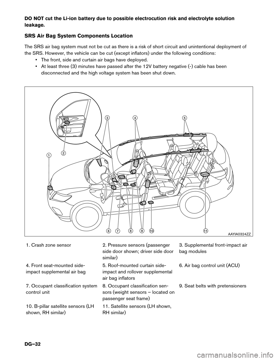
SRS Air Bag System Components Location
The SRS air bag system must not be cut as there is a risk of short circuit and unintentional deployment of
the SRS. However, the vehicle can be cut (except inflators) under the following conditions:• The front, side and curtain air bags have deployed.
• At least three (3) minutes have passed after the 12V battery negative (-) cable has been
disconnected and the high voltage system has been shut down.
1. Crash zone sensor 2. Pressure sensors (passenger side door shown; driver side door similar)3. Supplemental front-impact air
bag modules
4. Front seat-mounted side-
impact supplemental air bag 5. Roof-mounted curtain side-
impact and rollover supplemental
air bag inflators6. Air bag control unit (ACU)
7. Occupant classification system
control unit 8. Occupant classification sen-
sors (weight sensors – located on
passenger seat frame)9. Seat belts with pretensioners
10. B-pillar satellite sensors (LH
shown, RH similar) 11. Satellite sensors (LH shown,
RH similar)
4
891011
53
21
67AAYIA0324ZZ
DG–32
Page 37 of 50

4-1 Jump Starting Procedures
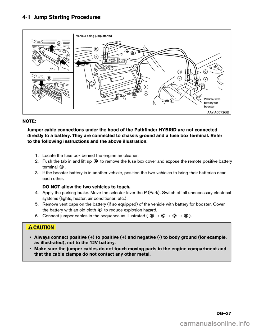
NOTE:Jumper cable connections under the hood of the Pathfinder HYBRID are not connected
directly to a battery. They are connected to chassis ground and a fuse box terminal. Refer
to the following instructions and the above illustration.
1. Locate the fuse box behind the engine air cleaner.
2. Push the tab in and lift up ○A
to remove the fuse box cover and expose the remote positive battery
terminal ○B
.
3. If the booster battery is in another vehicle, position the two vehicles to bring their batteries near each other.
DO NOT allow the two vehicles to touch.
4. Apply the parking brake. Move the selector lever the P (Park) . Switch off all unnecessary electrical systems (lights, heater, air conditioner, etc.) .
5. Remove vent caps on the battery (if so equipped) of the vehicle with battery for booster. Cover the battery with an old cloth ○F
to reduce explosion hazard.
6. Connect jumper cables in the sequence as illustrated ( ○B
�
○C
�
○D
�
○E
) .
• Always connect positive (+) to positive (+) and negative (-) to body ground (for example,
as illustrated) , not to the 12V battery.
• Make sure the jumper cables do not touch moving parts in the engine compartment and that the cable clamps do not contact any other metal.
F
A
E
D
B
B
+
C
+
Cloth
Vehicle being jump started
Vehicle with battery for booster
AAYIA0072GB
DG–37