Page 10 of 432
1. Engine hood (P. 3-17)
2. Windshield wiper and washer switch(P. 2-28)
3. Windshield (P. 8-20)
4. Moonroof (if so equipped) (P. 2-46)
5. Power windows (P. 2-43)
6. Door locks, NISSAN Intelligent Key®,
keys, request button (P. 3-4, 3-2, 3-2,
3-2)
7. Mirrors (P. 3-25)
8. Tire pressure (P. 8-32)
9. Flat tire (P. 6-3)
10. Tire chains (P. 8-40)
11. Headlight and turn signal switch
(P. 2-30)
12. Replacing bulbs (P. 8-30)
13. Fog light switch (if so equipped)
(P. 8-27)
See the page number indicated in paren-
theses for operating details.
WII0155
EXTERIOR FRONT
Illustrated table of contents0-3
Page 11 of 432
1. Rear window defroster switch (P. 2-29)
2. Interior trunk lid release (P. 3-19)
3. Trunk lid (P. 3-17)
4. Vehicle loading (P. 9-12)
5. Exterior trunk lid release/request button(P. 3-12)
6. Replacing bulbs (P. 8-30)
7. Fuel-filler cap, fuel recommendation
(P. 3-20, P. 9-28 )
8. Fuel-filler door (P. 3-20)
9. Child safety rear door locks (P. 3-6)
See the page number indicated in paren-
theses for operating details.
WII0156
EXTERIOR REAR
0-4Illustrated table of contents
Page 15 of 432
1. Power steering fluid reservoir (P. 8-13)
2. Engine oil filler cap (P. 8-10)
3. Brake fluid reservoir (P. 8-14)
4. Air cleaner (P. 8-19)
5. Fuse block (P. 8-22)
6. Battery (P. 8-15)
7. Fuse/fusible link box (P. 8-22)
8. Engine oil dipstick (P. 8-10)
9. Radiator cap (P. 8-8)
10. Drive belt location (P.8-17)
11. Engine coolant reservoir * (P. 8-8)
12. Windshield-washer fluid reservoir *(P. 8-14)
NOTE:
* Side covers removed for clarity.
See the page number indicated in paren-
theses for operating details.
WDI0662
ENGINE COMPARTMENT CHECK
LOCATIONS
0-8Illustrated table of contents
Page 16 of 432
Warninglight Name Page
or
Anti-lock Braking
System (ABS) warn-
ing light 2-11
or
Brake warning light 2-11
Charge warning
light
2-11
Engine oil pressure
warning light2-12
Low tire pressure
warning light2-12
Master warning light 2-14
Warning
light Name Page
Seat belt warning
light and chime 2-14
Supplemental air
bag warning light2-14
Indicator
light Name Page
Continuously Vari-
able Transmission
(CVT) indicator light 2-14
Continuously Vari-
able Transmission
(CVT) position indi-
cator light2-10
Cruise main switch
indicator light
2-15
Front passenger air
bag status light2-15
Indicator
light Name Page
High beam indicator
light (blue) 2-15
Malfunction Indica-
tor Light (MIL)2-15
Security indicator
light2-16
Side light and head-
light indicator light
(green)2-16
Slip indicator light 2-16
Turn signal/hazard
indicator lights
2-16
Vehicle Dynamic
Control OFF indica-
tor light2-16
WARNING/INDICATOR LIGHTS
Illustrated table of contents0-9
Page 19 of 432

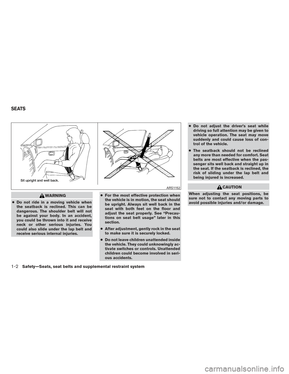
WARNING
●Do not ride in a moving vehicle when
the seatback is reclined. This can be
dangerous. The shoulder belt will not
be against your body. In an accident,
you could be thrown into it and receive
neck or other serious injuries. You
could also slide under the lap belt and
receive serious internal injuries. ●
For the most effective protection when
the vehicle is in motion, the seat should
be upright. Always sit well back in the
seat with both feet on the floor and
adjust the seat properly. See “Precau-
tions on seat belt usage” later in this
section.
● After adjustment, gently rock in the seat
to make sure it is securely locked.
● Do not leave children unattended inside
the vehicle. They could unknowingly ac-
tivate switches or controls. Unattended
children could become involved in seri-
ous accidents. ●
Do not adjust the driver’s seat while
driving so full attention may be given to
vehicle operation. The seat may move
suddenly and could cause loss of con-
trol of the vehicle.
● The seatback should not be reclined
any more than needed for comfort. Seat
belts are most effective when the pas-
senger sits well back and straight up in
the seat. If the seatback is reclined, the
risk of sliding under the lap belt and
being injured is increased.
CAUTION
When adjusting the seat positions, be
sure not to contact any moving parts to
avoid possible injuries and/or damage.
ARS1152
SEATS
1-2Safety—Seats, seat belts and supplemental restraint system
Page 23 of 432

●When returning the seatbacks to the
upright position, be certain they are
completely secured in the latched posi-
tion. If they are not completely secured,
passengers may be injured in an acci-
dent or sudden stop.
● Closely supervise children when they
are around cars to prevent them from
playing and becoming locked in the
trunk where they could be seriously in-
jured. Keep the car locked, with the rear
seatback and trunk lid securely latched
when not in use, and prevent children’s
access to car keys.
To fold down the driver side of the rear seat, reach
through the opening and pull on the strap
�1
located behind the seat.
The rear seats can be locked using the mechani-
cal key to prevent unauthorized access.
Secondary trunk lid release (if so
equipped)
For models with a rear center console, the trunk
can be accessed through the access panel be-
tween the rear seats, as shown.● Fold down the center arm rest.
● Insert the mechanical key into the trunk com-
partment access lid lock. Fold down the
trunk compartment access lid. For more in-
formation on the mechanical key, see
“NISSAN Intelligent Key® ” in the Pre-
driving checks and adjustments chapter.
● Pull the rear seat trunk release handle
�1.
WRS0867LPD0459
1-6Safety—Seats, seat belts and supplemental restraint system
Page 25 of 432

●Adjustable head restraints/headrests have
multiple notches along the stalk to lock them
in a desired adjustment position.
● The non-adjustable head
restraints/headrests have a single locking
notch to secure them to the seat frame.
● Proper Adjustment:
– For the adjustable type, align the head restraint/headrest so the center of your
ear is approximately level with the center
of the head restraint/headrest.
– If your ear position is still higher than the recommended alignment, place the head
restraint/headrest at the highest position.
● If the head restraint/headrest has been re-
moved, ensure that it is reinstalled and
locked in place before riding in that desig-
nated seating position.
Adjustable head restraint/headrest
components
1. Removable head restraint/headrest
2. Multiple notches
3. Lock knob
4. Stalks
Non-adjustable head restraint/
headrest components
1. Removable head restraint/headrest
2. Single Notch
3. Lock knob
4. Stalks
LRS2300LRS2299
1-8Safety—Seats, seat belts and supplemental restraint system
Page 26 of 432

Removable
Use the following procedure to remove the head
restraints/headrests.1. Pull the head restraint/headrest up to the highest position.
2. Push and hold the lock knob.
3. Remove the head restraint/headrest from the seat.
4.
Store the head restraint/headrest properly in a
secure place so it is not loose in the vehicle.
5. Reinstall and properly adjust the head restraint/headrest before an occupant uses
the seating position.
Install
1. Align the head restraint/headrest stalks withthe holes in the seat. Make sure the head
restraint/headrest is facing the correct di-
rection. The stalk with the notch (notches)
�1must be installed in the hole with the lock
knob
�2.
2. Push and hold the lock knob and the head restraint/headrest down.
3. Properly adjust the head restraint/headrest before an occupant uses the seating posi-
tion.
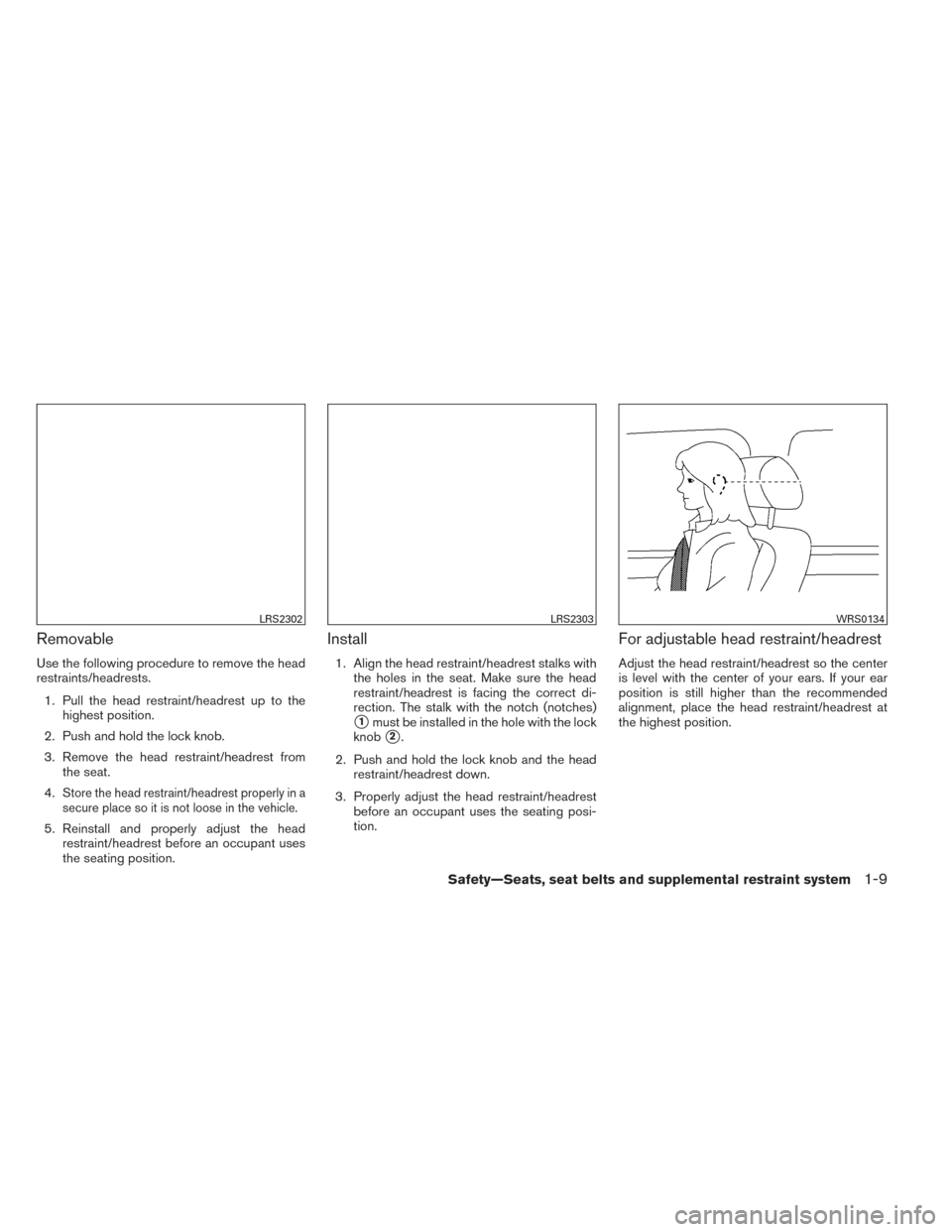
For adjustable head restraint/headrest
Adjust the head restraint/headrest so the center
is level with the center of your ears. If your ear
position is still higher than the recommended
alignment, place the head restraint/headrest at
the highest position.
LRS2302LRS2303WRS0134
Safety—Seats, seat belts and supplemental restraint system1-9