2014 NISSAN GT-R wheel
[x] Cancel search: wheelPage 35 of 354
GTR-28GT-R Overview
The GT-R dual clutch transmission is a newly-
developed system that uses an electronically
controlled multiple-disc wet clutch attached to
the highly efficient manual transmission. This
transmission has two driving modes.
.
&Aposition (Automatic gearshift):
allows automatic shifting of the manual
transmission.
.
&Mposition (Manual gearshift):
allows quick shifting of the manual transmis-
sion.
NOTE:
When starting or driving on a steep uphill
grade, shift to the
&Mposition and operate
the paddle shifter to shift down to 1st gear
similar to a manual transmission vehicle.
The GT-R dual clutch transmission was devel-
oped specifically to maximize vehicle perfor-
mance and driving enjoyment. The GT-R
transmission components were designed using
different engineering standards than typical
passenger car transmissions. Because of this,
the GT-R has different operating characteristics,
and various rattle noises may be heard during
some driving conditions because of the follow-
ing items:
. Gear clearances .
Ultralight flywheel
. Dry sump lubrication
These noises do not indicate that there is a
malfunction.
DUAL CLUTCH TRANSMISSION
Page 36 of 354
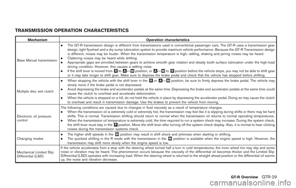
TRANSMISSION OPERATION CHARACTERISTICS
MechanismOperation characteristics
Base Manual transmission
.The GT-R transmission design is different from transmissions used in conventional passenger cars. The GT-R uses a transmission gear
design, light flywheel and a dry sump lubrication system to provide maximum vehicle performance. Because the GT-R Transmission design
is different, noises may be louder. When the transmission temperature is high, rattling, shaking and jarring noises may be heard.
.Clattering noises may be heard while shifting..Appropriate gaps are provided between gears to achieve smooth gear rotation and steady tooth surface lubrication under the high-load
driving condition. However, this causes a rattling noise.
.If the shift lever is moved from&Rto&A↔&Mposition, or&A↔&Mto&Rposition before the vehicle stops, you may not be able to shift gear
or it may take longer to shift gear. Make sure to depress the brake pedal and check that the vehicle has stopped before shifting.
Multiple disc wet clutch
.When stopping the vehicle with the shift lever in the&Ror&A↔&Mposition, be sure to firmly depress the brake pedal. The vehicle may
slowly move if the brake pedal is not depressed.
.Avoid depressing the brake and accelerator pedals at the same time. Depressing the brake and accelerator pedals at the same time could
cause the clutch to overheat and accelerate deterioration.
.When the vehicle is stopped on a hill, do not hold the vehicle in place by depressing the accelerator pedal. Doing so may cause the clutch
to overheat and result in transmission damage. Use the brakes to prevent the vehicle from moving.
Electronic oil pressure
control The following conditions are caused due to changes in fluid viscosity as a result of temperature changes.
.When the transmission oil is extremely cold or extremely hot, the transmission may feel like it is slipping during shifts or there may be hard
shifts. This is normal. Transmission shifting should return to normal when the transmission oil returns to normal operating temperatures.
.When the transmission oil temperature is extremely cold, the time required to run a system check may increase. During the system check,
the shift lever must stay in the&Pposition. Move the shift lever after turning off the system check display. Also, it is normal to hear clicking
noises during the transmission systems check.
Changing modes
.The higher shift speeds in the&Mposition may result in shift shock and jerkiness when starting or shifting..The quickest shifting in the R mode with the transmission in the&Mposition is available when the engine speed is high. However, the
transmission may shift more slowly when the engine speed is low.
Mechanical Limited Slip
Differential (LSD) If the vehicle accelerates from a stop with the steering wheel turned half a turn in cold temperatures, the inner wheel tire may slip and some
noise or vibration may be heard. This phenomenon occurs because the viscosity of the differential oil becomes thicker and the Limited Slip
Differential (LSD) operates with increasing load. When the steering wheel is returned to the straight ahead position or the differential oil warms
up, the noise and vibration decrease.
GT-R OverviewGTR-29
Page 37 of 354
GTR-30GT-R Overview
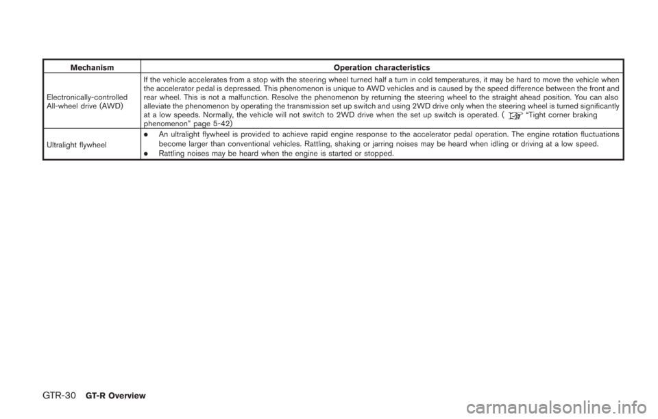
MechanismOperation characteristics
Electronically-controlled
All-wheel drive (AWD) If the vehicle accelerates from a stop with the steering wheel turned half a turn in cold temperatures, it may be hard to move the vehicle when
the accelerator pedal is depressed. This phenomenon is unique to AWD vehicles and is caused by the speed difference between the front and
rear wheel. This is not a malfunction. Resolve the phenomenon by returning the steering wheel to the straight ahead position. You can also
alleviate the phenomenon by operating the transmission set up switch and using 2WD drive only when the steering wheel is turned significantly
at a low speeds. Normally, the vehicle will not switch to 2WD drive when the set up switch is operated. (
“Tight corner braking
phenomenon” page 5-42)
Ultralight flywheel
.An ultralight flywheel is provided to achieve rapid engine response to the accelerator pedal operation. The engine rotation fluctuations
become larger than conventional vehicles. Rattling, shaking or jarring noises may be heard when idling or driving at a low speed.
.Rattling noises may be heard when the engine is started or stopped.
Page 41 of 354
0-4Illustrated table of contents
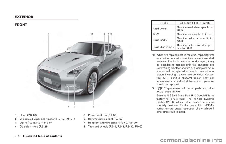
FRONT
1. Hood (P.3-18)
2. Windshield wiper and washer (P.2-47, P.8-21)
3. Doors (P.3-2, P.3-4, P.3-8)
4. Outside mirrors (P.3-28)5. Power windows (P.2-59)
6. Daytime running light (P.2-50)
7. Headlight and turn signal (P.2-50, P.8-29)
8. Tires and wheels (P.5-4, P.6-3, P.8-32, P.9-9) ITEMS GT-R SPECIFIED PARTS
Road wheel Genuine road wheel specific to
GT-R
Tire*1 Genuine tire specific to GT-R
Brake pad*2 Genuine brake pad specific to
GT-R
Brake disc rotor*2 Genuine brake disc rotor spe-
cific to GT-R
*1: When tire replacement is required, replacing tires as a set of four with new tires is recommended.
However, if a tire is punctured or damaged, it may
be possible to replace only the damaged tire.
Determining whether one tire or a complete set of
tires should be replaced is based on a number of
factors including tire wear and condition. Contact
your GT-R certified NISSAN dealer. They can
recommend if an individual tire or a complete set
should be replaced.
*2:
“Replacement of brake pads and disc
rotors” page GTR-6
Genuine NISSAN Brake Fluid R35 Special II is the
factory fill brake fluid. The Vehicle Dynamic
Control (VDC) unit and other related parts were
specially designed for this brake fluid. NISSAN
cannot ensure proper operation of the vehicle if
other brake fluid is used.
EXTERIOR
Page 44 of 354
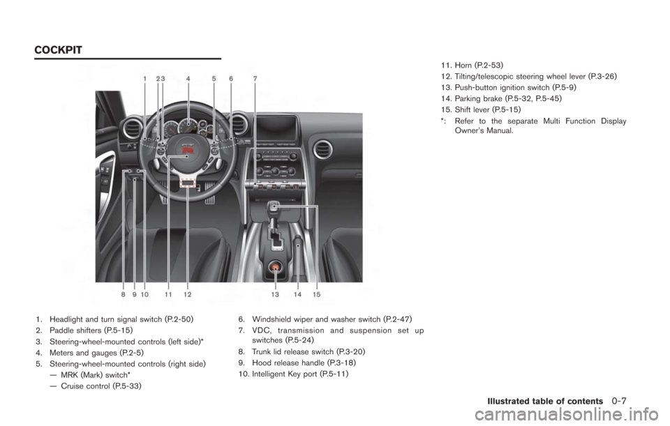
1. Headlight and turn signal switch (P.2-50)
2. Paddle shifters (P.5-15)
3. Steering-wheel-mounted controls (left side)*
4. Meters and gauges (P.2-5)
5. Steering-wheel-mounted controls (right side)— MRK (Mark) switch*
— Cruise control (P.5-33) 6. Windshield wiper and washer switch (P.2-47)
7. VDC, transmission and suspension set up
switches (P.5-24)
8. Trunk lid release switch (P.3-20)
9. Hood release handle (P.3-18)
10. Intelligent Key port (P.5-11) 11. Horn (P.2-53)
12. Tilting/telescopic steering wheel lever (P.3-26)
13. Push-button ignition switch (P.5-9)
14. Parking brake (P.5-32, P.5-45)
15. Shift lever (P.5-15)
*: Refer to the separate Multi Function Display
Owner’s Manual.
Illustrated table of contents0-7
COCKPIT
Page 48 of 354
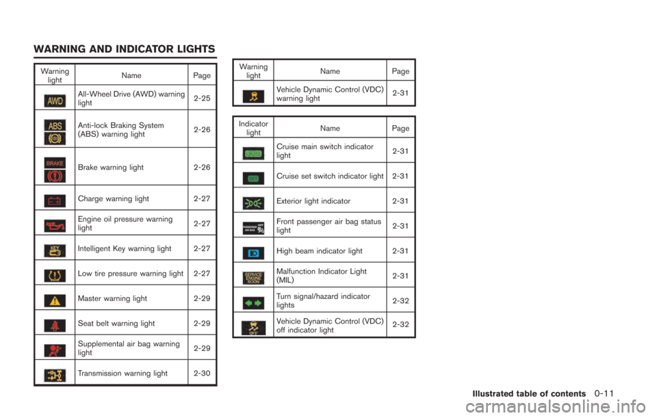
Warninglight Name
Page
All-Wheel Drive (AWD) warning
light 2-25
Anti-lock Braking System
(ABS) warning light2-26
Brake warning light
2-26
Charge warning light2-27
Engine oil pressure warning
light 2-27
Intelligent Key warning light 2-27
Low tire pressure warning light 2-27
Master warning light
2-29
Seat belt warning light 2-29
Supplemental air bag warning
light 2-29
Transmission warning light 2-30 Warning
light Name
Page
Vehicle Dynamic Control (VDC)
warning light 2-31
Indicator light Name
Page
Cruise main switch indicator
light 2-31
Cruise set switch indicator light 2-31
Exterior light indicator
2-31
Front passenger air bag status
light 2-31
High beam indicator light 2-31
Malfunction Indicator Light
(MIL)2-31
Turn signal/hazard indicator
lights
2-32
Vehicle Dynamic Control (VDC)
off indicator light2-32
Illustrated table of contents0-11
WARNING AND INDICATOR LIGHTS
Page 83 of 354
1-34Safety — Seats, seat belts and supplemental restraint system
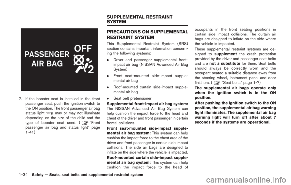
7. If the booster seat is installed in the frontpassenger seat, push the ignition switch to
the ON position. The front passenger air bag
status light
may or may not illuminate
depending on the size of the child and the
type of booster seat used. (
“Front
passenger air bag and status light” page
1-41)
PRECAUTIONS ON SUPPLEMENTAL
RESTRAINT SYSTEM
This Supplemental Restraint System (SRS)
section contains important information concern-
ing the following systems:
. Driver and passenger supplemental front-
impact air bag (NISSAN Advanced Air Bag
System)
. Front seat-mounted side-impact supple-
mental air bag
. Roof-mounted curtain side-impact supple-
mental air bag
. Seat belt pretensioner
Supplemental front-impact air bag system:
The NISSAN Advanced Air Bag System can
help cushion the impact force to the head and
chest of the driver and front passenger in certain
frontal collisions.
Front seat-mounted side-impact supple-
mental air bag system: This system can help
cushion the impact force to the chest area of the
driver and front passenger in certain side impact
collisions. The side air bags are designed to
inflate on the side where the vehicle is impacted.
Roof-mounted curtain side-impact supple-
mental air bag system: This system can help
cushion the impact force to the head of occupants in the front seating positions in
certain side impact collisions. The curtain air
bags are designed to inflate on the side where
the vehicle is impacted.
These supplemental restraint systems are de-
signed to
supplement the crash protection
provided by the driver and passenger seat belts
and are not a substitute for them. Seat belts
should always be correctly worn and the
occupant seated a suitable distance away from
the steering wheel, instrument panel and door
finishers. (
“Seat belts” page 1-7)
The supplemental air bags operate only
when the ignition switch is in the ON
position.
After pushing the ignition switch to the ON
position, the supplemental air bag warning
light illuminates. The supplemental air bag
warning light will turn off after about 7
seconds if the systems are operational.
SUPPLEMENTAL RESTRAINT
SYSTEM
Page 85 of 354
1-36Safety — Seats, seat belts and supplemental restraint system
back against the seatback and as
far-away as practical from the steer-
ing wheel or instrument panel. Al-
ways use the seat belts.
. The driver and front passenger seat
belt buckles are equipped with
sensors that detect if the seat belts
are fastened. The Advanced Air Bag
System monitors the severity of a
collision and seat belt usage then
inflates the air bags as needed.
Failure to properly wear seat belts
can increase the risk or severity of
injury in an accident.
. The front passenger seat is
equipped with an occupant classifi-
cation sensor (pattern sensor) that
turns the front passenger air bag
OFF under some conditions. This
sensor is only used in this seat.
Failure to be properly seated and
wearing the seat belt can increase
the risk or severity of injury in an
accident. (
“Front passenger air
bag and status light” page 1-41)
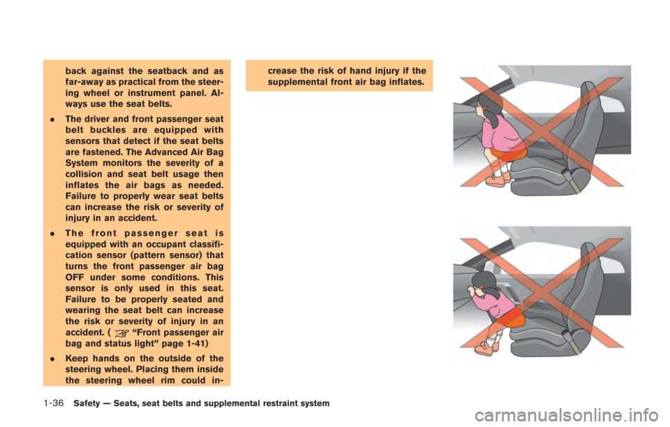
. Keep hands on the outside of the
steering wheel. Placing them inside
the steering wheel rim could in- crease the risk of hand injury if the
supplemental front air bag inflates.