2014 NISSAN GT-R lights
[x] Cancel search: lightsPage 150 of 354
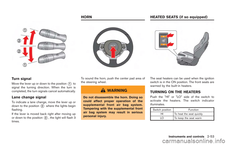
Turn signal
Move the lever up or down to the position*1to
signal the turning direction. When the turn is
completed, the turn signals cancel automatically.
Lane change signal
To indicate a lane change, move the lever up or
down to the position
*2where the lights begin
flashing.
If the lever is moved back right after moving up
or down to the position
*2, the light will flash 3
times.
To sound the horn, push the center pad area of
the steering wheel.
WARNING
Do not disassemble the horn. Doing so
could affect proper operation of the
supplemental front air bag system.
Tampering with the supplemental front
air bag system may result in serious
personal injury.
The seat heaters can be used when the ignition
switch is in the ON position. The front seats are
warmed by the built-in heaters.
TURNING ON THE HEATERS
Push the "HI" or "LO" side of the switch to
activate the heaters. The switch indicator
illuminates.
Switch position Function
HI To heat the seat quickly
LO To keep the seat warm
Instruments and controls2-53
HORN HEATED SEATS (if so equipped)
Page 151 of 354
2-54Instruments and controls
TURNING OFF THE HEATERS
Move the switch to the level position. The switch
indicator turns off.
WARNING
Do not use or allow occupants to use
the seat heater if you or the occupants
cannot monitor elevated seat tempera-
tures or have an inability to feel pain in
those body parts in contact with the
seat. Use of the seat heater by such
people could result in serious injury.
CAUTION
.Do not put anything on the seat
which insulates heat, such as a
blanket, cushion, seat cover, etc.
Otherwise, the seat may become
overheated.
. Do not place anything hard or heavy
on the seat or pierce it with a pin or
similar object. This may result in
damage to the heater.
. Any liquid spilled on the heated seat
should be removed immediately with a dry cloth.
. If any malfunctions are found or the
heated seat does not operate, turn
the switch off and have the system
checked by a GT-R certified NISSAN
dealer.
NOTICE
.The battery could run down if the
seat heater is operated while the
engine is not running.
. Do not use the seat heater for
extended periods or when no one
is using the seat.
. When cleaning the seat, never use
gasoline, thinner, or any similar
materials.
CAUTION
.The outlet and plug may be hot
during or immediately after use.
. Do not use with accessories that
exceed a 12 volt, 120W (10A) power
draw. Do not use double adapters or
more than one electrical accessory.
. This power outlet is not designed
for use with a cigarette lighter unit.
. Before inserting or disconnecting a
plug, be sure the electrical acces-
sory being used is turned OFF.
. When not in use, be sure to close
the cap. Do not allow water to
contact the outlet.
NOTICE
.Use power outlet with the engine
running to avoid discharging the
vehicle battery.
. Avoid using power outlet when the
air conditioner, headlights or rear
window defroster is on.
POWER OUTLETS
Page 159 of 354
2-62Instruments and controls
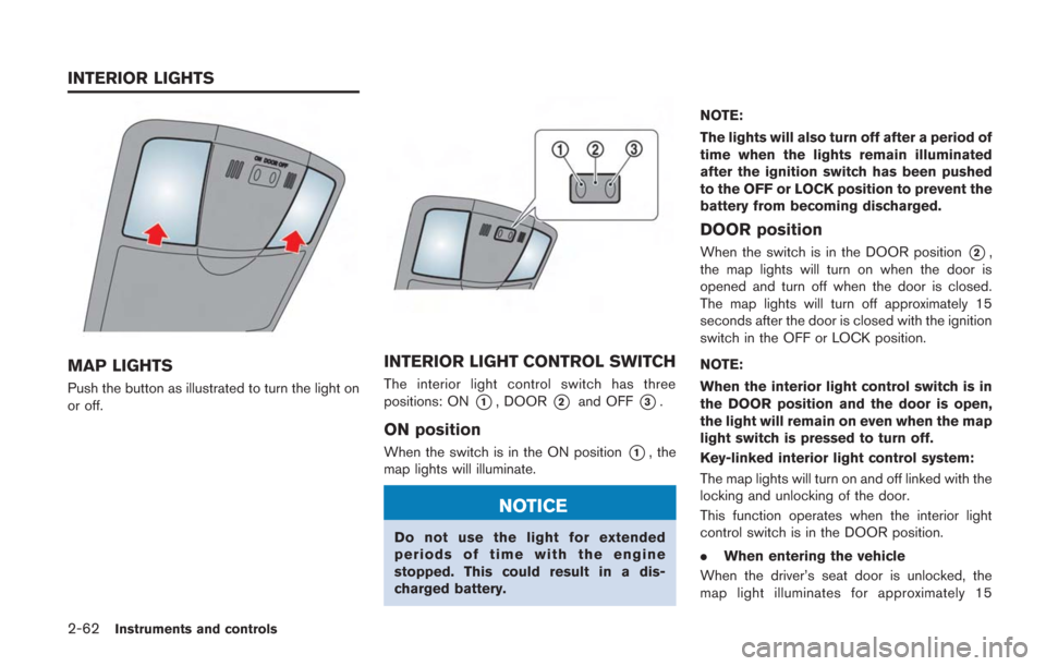
MAP LIGHTS
Push the button as illustrated to turn the light on
or off.
INTERIOR LIGHT CONTROL SWITCH
The interior light control switch has three
positions: ON
*1, DOOR*2and OFF*3.
ON position
When the switch is in the ON position*1, the
map lights will illuminate.
NOTICE
Do not use the light for extended
periods of time with the engine
stopped. This could result in a dis-
charged battery. NOTE:
The lights will also turn off after a period of
time when the lights remain illuminated
after the ignition switch has been pushed
to the OFF or LOCK position to prevent the
battery from becoming discharged.
DOOR position
When the switch is in the DOOR position*2,
the map lights will turn on when the door is
opened and turn off when the door is closed.
The map lights will turn off approximately 15
seconds after the door is closed with the ignition
switch in the OFF or LOCK position.
NOTE:
When the interior light control switch is in
the DOOR position and the door is open,
the light will remain on even when the map
light switch is pressed to turn off.
Key-linked interior light control system:
The map lights will turn on and off linked with the
locking and unlocking of the door.
This function operates when the interior light
control switch is in the DOOR position.
. When entering the vehicle
When the driver’s seat door is unlocked, the
map light illuminates for approximately 15
INTERIOR LIGHTS
Page 160 of 354
seconds, then it turns off.
While the map light is on, if the ignition switch is
pushed to the ACC or ON position, or if the
driver’s side door is locked, the light turns off.
.When exiting the vehicle
When the ignition switch is pushed to the OFF
or LOCK position, the map lights turn on for
approximately 15 seconds, then it turns off.
If the driver’s side door is locked while the map
lights are on, the light turns off.
NOTE:
It is possible to cancel the key-linked
interior light control system setting. See
the separate Multi Function Display Own-
er’s Manual.
OFF position
When the switch is in the OFF position*3, the
map lights will not illuminate, regardless of any
condition.
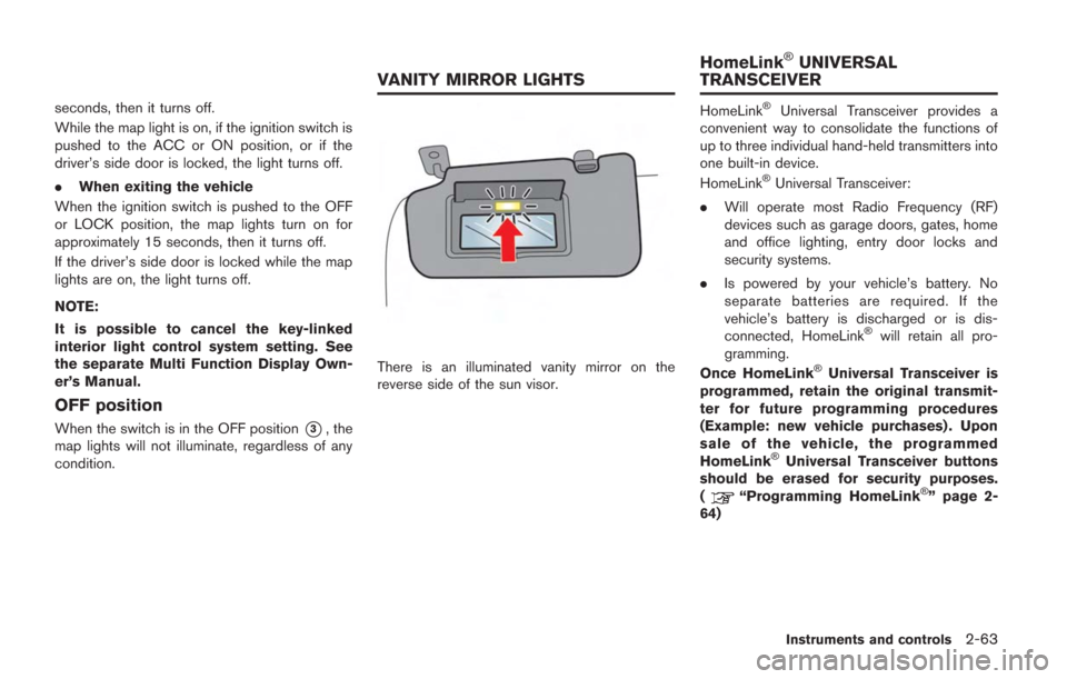
There is an illuminated vanity mirror on the
reverse side of the sun visor.
HomeLink®Universal Transceiver provides a
convenient way to consolidate the functions of
up to three individual hand-held transmitters into
one built-in device.
HomeLink
®Universal Transceiver:
. Will operate most Radio Frequency (RF)
devices such as garage doors, gates, home
and office lighting, entry door locks and
security systems.
. Is powered by your vehicle’s battery. No
separate batteries are required. If the
vehicle’s battery is discharged or is dis-
connected, HomeLink
®will retain all pro-
gramming.
Once HomeLink
®Universal Transceiver is
programmed, retain the original transmit-
ter for future programming procedures
(Example: new vehicle purchases) . Upon
sale of the vehicle, the programmed
HomeLink
®Universal Transceiver buttons
should be erased for security purposes.
(
“Programming HomeLink®” page 2-
64)
Instruments and controls2-63
VANITY MIRROR LIGHTS HomeLink
®UNIVERSAL
TRANSCEIVER
Page 178 of 354
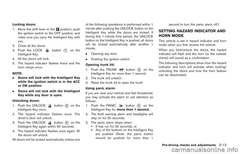
Locking doors:
1. Move the shift lever to the
&Pposition, push
the ignition switch to the OFF position, and
make sure you carry the Intelligent Key with
you.
2. Close all the doors.
3. Push the LOCK
button*1on the
Intelligent Key.
4. All the doors will lock.
5. The hazard indicator flashes twice and the horn chirps once.
NOTE:
. Doors will lock with the Intelligent Key
while the ignition switch is in the ACC
or ON position.
. Doors will not lock with the Intelligent
Key while any door is open.
Unlocking doors:
1. Push the UNLOCK
button*2on the
Intelligent Key once.
2. The hazard indicator flashes once. The driver’s door will unlock.
3. Push the UNLOCK
button*2on the
Intelligent Key again within 60 seconds.
4. The hazard indicator flashes once again. All the doors will unlock.
All doors will be locked automatically unless one of the following operations is performed within 1
minute after pushing the UNLOCK button on the
Intelligent Key while the doors are locked. If
during this 1-minute time period, the UNLOCK
button on the Intelligent Key is pushed, all doors
will be locked automatically after another 1
minute.
.
Opening any door
. Pushing the ignition switch
Opening trunk lid:
1. Push the TRUNK
button*3on the
Intelligent Key for more than 1 second.
2. The trunk will unlatch.
3. Raise the trunk lid to open the trunk.
Using panic alarm:
If you are near your vehicle and feel threatened,
you may activate the alarm to call attention as
follows:
1. Push the PANIC
button*4on the
Intelligent Key for more than 1 second.
2. The theft warning alarm and headlights will stay on for 25 seconds.
3. The panic alarm stops when:
.It has run for 25 seconds, or.Any of the buttons on the Intelligent Key
are pushed. (Note: the panic button
should be pushed for more than 1 second to turn the panic alarm off.)
SETTING HAZARD INDICATOR AND
HORN MODE
This vehicle is set in hazard indicator and horn
mode when you first receive the vehicle.
When you lock/unlock the doors, the hazard
indicator will flash and the horn (or the outside
chime) will sound as a confirmation.
The following descriptions show how the hazard
indicator and horn will activate when locking/
unlocking the doors and how the horn feature
can be deactivated.
Pre-driving checks and adjustments3-13
Page 192 of 354
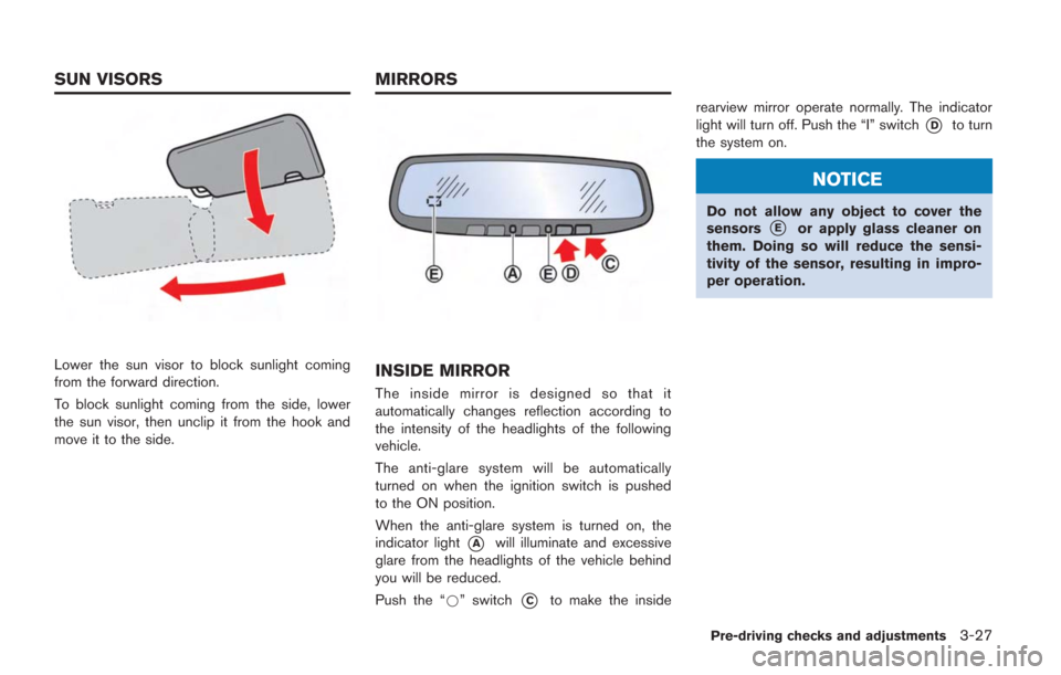
Lower the sun visor to block sunlight coming
from the forward direction.
To block sunlight coming from the side, lower
the sun visor, then unclip it from the hook and
move it to the side.INSIDE MIRROR
The inside mirror is designed so that it
automatically changes reflection according to
the intensity of the headlights of the following
vehicle.
The anti-glare system will be automatically
turned on when the ignition switch is pushed
to the ON position.
When the anti-glare system is turned on, the
indicator light
*Awill illuminate and excessive
glare from the headlights of the vehicle behind
you will be reduced.
Push the “*” switch
*Cto make the inside rearview mirror operate normally. The indicator
light will turn off. Push the “I” switch
*Dto turn
the system on.
NOTICE
Do not allow any object to cover the
sensors*Eor apply glass cleaner on
them. Doing so will reduce the sensi-
tivity of the sensor, resulting in impro-
per operation.
Pre-driving checks and adjustments3-27
SUN VISORS MIRRORS
Page 210 of 354
.Make sure the area around the vehicle is
clear.
. Check fluid levels such as engine oil, cool-
ant, brake fluid and window washer fluid as
frequently as possible, or at least whenever
you refuel.
. Check that all windows and lights are clean.
. Visually inspect tires for their appearance
and condition. Also check tires for proper
inflation.
. Lock all doors.
. Position seat.
. Adjust inside and outside mirrors.
. Fasten seat belts and ask all passengers to
do likewise.
. Check the operation of warning lights when
the ignition switch is pushed to the ON
position. (
“Warning/indicator lights
and audible reminders” page 2-25)
NOTE:
. This vehicle includes spark plugs that
are designed for maximum perfor-
mance. If the start time becomes long-
er, the plugs may be fouled, making the
engine difficult to start. If this occurs,
start the engine using the procedure
described in this section.
. A click sound may be heard when the
brake pedal is depressed and released.
This is normal.
. A low rattling operating sound may
occur when the engine is started or
stopped. This is because of the trans-
mission gear design, light flywheel and
dry sump lubrication system used in
this transmission. This does not indi-
cate that there is a malfunction. This
sound is likely to occur in particular if
the engine is stopped when the tem-
perature of the transmission oil is high.
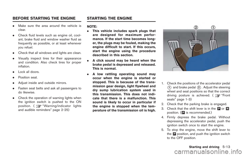
1. Check the positions of the accelerator pedal
*1and brake pedal*2. Adjust the steering
wheel and seat positions so that the correct
driving posture is achieved. (
“Front
seats” page 1-3)
2. Check that the parking brake is engaged.
3. Check that the shift lever is in the
&Por&N
position. (&Pis recommended.)
4. Firmly depress the brake pedal. Without depressing the accelerator pedal, push the
ignition switch once to start the engine.
5. To stop the engine, move the shift lever to the
&Pposition, and push the ignition switch
to the OFF position.
Starting and driving5-13
BEFORE STARTING THE ENGINE STARTING THE ENGINE
Page 226 of 354
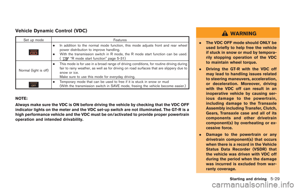
Vehicle Dynamic Control (VDC)
Set up modeFeatures
.In addition to the normal mode function, this mode adjusts front and rear wheel
power distribution to improve handling.
.With the transmission switch in R mode, the R mode start function can be used.
(“R mode start function” page 5-31)
Normal (light is off)
.This mode is for use in a broad range of driving conditions, for routine driving during
fair to rainy weather, as well as for driving on road surfaces that are slippery due to
snow or ice.
Make sure to use this mode for everyday driving.
.Temporary mode that can be used to free if it is stuck in snow or mud
(With the transmission switch in SAVE mode, freeing the vehicle become easier.)
NOTE:
Always make sure the VDC is ON before driving the vehicle by checking that the VDC OFF
indicator lights on the meter and the VDC set-up switch are not illuminated. The GT-R is a
high performance vehicle and the VDC must be on/activated to provide proper powertrain
operation and intended drivability.
WARNING
. The VDC OFF mode should ONLY be
used briefly to help free the vehicle
if stuck in snow or mud by tempora-
rily stopping operation of the VDC
to maintain wheel torque.
. Driving the GT-R with the VDC off
may lead to handling issues related
to steering maneuvers, acceleration,
or deceleration. Moreover, driving
with the VDC off can result in an
inoperative vehicle by causing ser-
ious damage to the powertrain,
including damage to the Transaxle
Assembly including Transfer, Clutch,
Gears, Transaxle case and all of its
components and other drivetrain
component(s) by overheating or ex-
cessive force.
. Damage to the powertrain or any
drivetrain component(s) that occurs
when there is a record in the Vehicle
Status Data Recorder (VSDR) that
the vehicle was driven with VDC off
during the period when the damage
was incurred is excluded from war-
ranty coverage.
Starting and driving5-29