2014 NISSAN GT-R instrument panel
[x] Cancel search: instrument panelPage 218 of 354
.Fifth gear:
Use this position for all normal forward
driving at highway speeds. Engine braking
is weaker in this position.
. Sixth gear:
Use this position for all normal forward
driving at highway speeds. Engine braking
is weakest in this position.
Suggested maximum speed in each gear:
Downshift to a lower gear if the engine is not
running smoothly, or if you need to accelerate.
Do not exceed the maximum suggested speed
(shown below) in any gear. For level road
driving, use the highest gear suggested for that
speed. Always observe posted speed limits, and
drive according to the road conditions that will
ensure safe operation. Do not over-rev the
engine when shifting to a lower gear as it may
cause engine damage or loss of vehicle control.
Gear MPH (km/h)
1st 36 (58)
2nd 63 (102)
3rd 91 (148)
4th —
5th —
6th —
NOTE:
The paddle shifters are made from magne-
sium alloy. Only clear coating is applied to
their surfaces to utilize the unique casting
patterns and the texture of the material
itself.
DRIVING TIPS
After starting the engine, fully depress the foot
brake pedal and push the shift lever button
before shifting the shift lever from the
&Pposition
to the&R,&N,or&A↔&Mposition. Be sure the
vehicle is fully stopped before attempting to shift
the shift lever.
The transmission is designed so that the foot
brake pedal must be depressed before shifting
from
&Pto any other position.
The shift lever cannot be moved out of the
&P
position and into any other position with the
ignition switch other in the LOCK, OFF or ACC
position.
When accelerating from a stop
Keep the foot brake pedal depressed and push
the shift lever button to shift into a driving gear
as following:
. To drive forward, move the shift lever to the
&A↔&Mposition. .
To back up, move the shift lever to the
&R
position.
Starting on level ground or an uphill:
1. Check the shift lever position indicator on the instrument panel to confirm that the
driving gear is selected.
2. Release the parking brake.
3. Release the foot brake pedal gradually, then slowly depress the accelerator pedal to start
the vehicle in motion.
(
“R mode start function” page 5-31)
NOTE:
. To prevent the clutch from overheating
when the parking brake is applied,
engine output is limited when the
accelerator pedal is depressed. In par-
ticular, the vehicle may not start
smoothly when the accelerator pedal
is depressed with the parking brake
applied on an uphill grade. To enable
smooth starting, release the parking
brake before moving the vehicle.
. The hill start assist function operates
when the vehicle is accelerating from a
stop on an uphill. (
“Hill Start
Assist” page 5-37)
Starting and driving5-21
Page 221 of 354
5-24Starting and driving
the brakes normally based on traffic and road
conditions.
The metallic brake pads and brake disc rotor
may rust together when the brakes are not
applied:
.If the vehicle is not idled for 20 seconds
without the brakes applied, or if the brakes
are applied when the vehicle is shut off, the
rotor and pads can rust together, even when
the brake pads are dry.
. If the brakes are wet when the vehicle is
parked and the parking brake is applied for a
long time.
Contact a GT-R certified NISSAN dealer if the
brake pads and brake rotor have rusted
together.
1. Bring the vehicle to a complete stop.
2. With the foot brake pedal depressed, apply the parking brake.
3. Move the shift lever to the
&Pposition.
4. Check the shift lever position indicator on the instrument panel to confirm that the
&P
position is selected.
5. Push the ignition switch to stop the engine.
WARNING
Before exiting the vehicle, be sure to
move the shift lever to the&Pposition
and stop the engine. If the engine is
running and the shift lever is not in the
&Pposition, the vehicle may start mov-
ing due to partial engagement of the
clutch or to the effects of gravity on a
slope, or the vehicle may suddenly
accelerate due to accidental operation
of the accelerator pedal, possibly caus-
ing an accident.
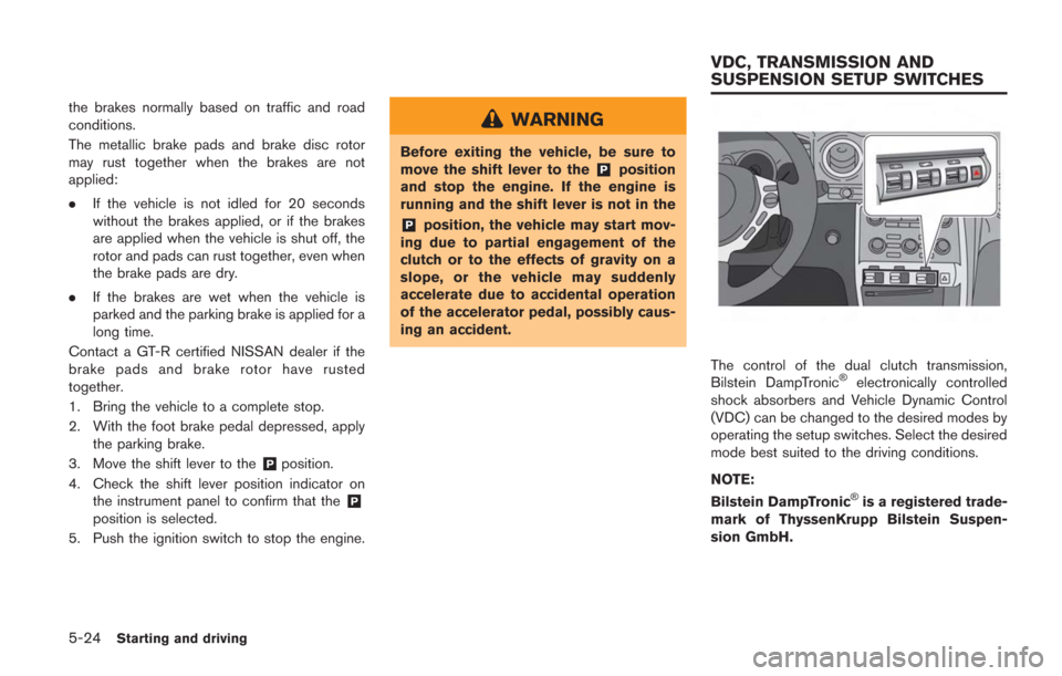
The control of the dual clutch transmission,
Bilstein DampTronic®electronically controlled
shock absorbers and Vehicle Dynamic Control
(VDC) can be changed to the desired modes by
operating the setup switches. Select the desired
mode best suited to the driving conditions.
NOTE:
Bilstein DampTronic
®is a registered trade-
mark of ThyssenKrupp Bilstein Suspen-
sion GmbH.
VDC, TRANSMISSION AND
SUSPENSION SETUP SWITCHES
Page 232 of 354
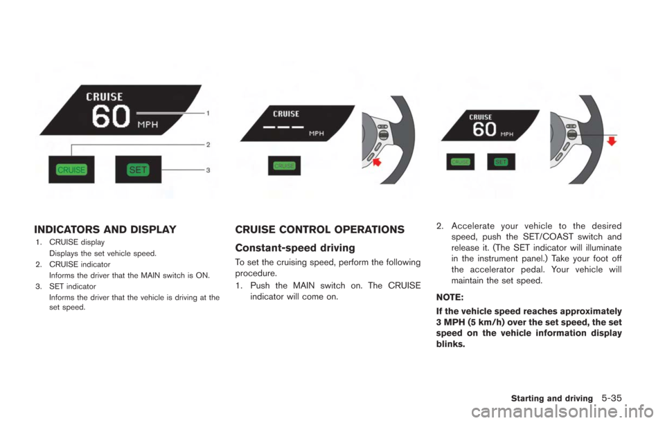
INDICATORS AND DISPLAY
1. CRUISE displayDisplays the set vehicle speed.
2. CRUISE indicator
Informs the driver that the MAIN switch is ON.
3. SET indicator Informs the driver that the vehicle is driving at the
set speed.
CRUISE CONTROL OPERATIONS
Constant-speed driving
To set the cruising speed, perform the following
procedure.
1. Push the MAIN switch on. The CRUISEindicator will come on.
2. Accelerate your vehicle to the desiredspeed, push the SET/COAST switch and
release it. (The SET indicator will illuminate
in the instrument panel.) Take your foot off
the accelerator pedal. Your vehicle will
maintain the set speed.
NOTE:
If the vehicle speed reaches approximately
3 MPH (5 km/h) over the set speed, the set
speed on the vehicle information display
blinks.
Starting and driving5-35
Page 245 of 354
5-48Starting and driving
ANTI-LOCK BRAKING SYSTEM
(ABS)
WARNING
.The Anti-lock Braking System (ABS)
is a sophisticated device, but it
cannot prevent accidents resulting
from careless or dangerous driving
techniques. It can help maintain
vehicle control during braking on
slippery surfaces. Remember that
stopping distances on slippery sur-
faces will be longer than on normal
surfaces even with ABS. Stopping
distances may also be longer on
rough, gravel or snow covered
roads, or if you are using tire chains.
Always maintain a safe distance
from the vehicle in front of you.
Ultimately, the driver is responsible
for safety.
. Tire type and condition may also
affect braking effectiveness. When
replacing tires, install the specified
size of tires on all four wheels.
The Anti-lock Braking System (ABS) controls the brakes so the wheels do not lock during hard
braking or when braking on slippery surfaces.
The system detects the rotation speed at each
wheel and varies the brake fluid pressure to
prevent each wheel from locking and sliding. By
preventing each wheel from locking, the system
helps the driver maintain steering control and
helps to minimize swerving and spinning on
slippery surfaces.
Using the system
Depress the brake pedal and hold it down.
Depress the brake pedal with firm steady
pressure, but do not pump the brakes. The
ABS will operate to prevent the wheels from
locking up. Steer the vehicle to avoid obstacles.
WARNING
Do not pump the brake pedal. Doing so
may result in increased stopping dis-
tances.
Self-test feature
The ABS includes electronic sensors, electric
pumps, hydraulic solenoids and a computer. The
computer has a built-in diagnostic feature that
tests the system each time you start the engine
and move the vehicle at a low speed in forwardor reverse. When the self-test occurs, you may
hear a “clunk” noise and/or feel a pulsation in the
brake pedal. This does not indicate that there is
a malfunction. If the computer senses a mal-
function, it switches the ABS off and illuminates
the ABS warning light on the instrument panel.
The brake system then operates normally, but
without anti-lock assistance.
If the ABS warning light illuminates during the
self-test or while driving, have the vehicle
checked by a GT-R certified NISSAN dealer.
Normal operation
The ABS operates at speeds above 3 to 6 MPH
(5 to 10 km/h). The speed varies according to
road conditions.
When the ABS senses that one or more wheels
are close to locking up, the actuator rapidly
applies and releases hydraulic pressure. This
action is similar to pumping the brakes very
quickly. You may feel a pulsation in the brake
pedal and hear a noise from under the hood or
feel a vibration from the actuator when it is
operating. This is normal and indicates that the
ABS is operating properly. However, the pulsa-
tion may indicate that road conditions are
hazardous and extra care is required while
driving.
BRAKE ASSIST
Page 246 of 354
The Vehicle Dynamic Control (VDC) system
uses various sensors to monitor driver inputs
and vehicle motion. Under certain driving con-
ditions, the VDC system helps to perform the
following functions.
.Controls brake pressure to reduce wheel
slip on one slipping drive wheel so power is
transferred to a non slipping drive wheel on
the same axle.
. Controls brake pressure and engine output
to reduce drive wheel slip based on vehicle
speed (traction control function) .
. Controls brake pressure at individual wheels
and engine output to help the driver maintain
control of the vehicle in the following
conditions:
— understeer (vehicle tends to not follow
the steered path despite increased
steering input)
— oversteer (vehicle tends to spin due to certain road or driving conditions) .
The VDC system can help the driver to maintain
control of the vehicle, but it cannot prevent loss
of vehicle control in all driving situations.
When the VDC system operates, the VDC
warning light
in the instrument panel flashes
so note the following: .
The road may be slippery or the system may
determine some action is required to help
keep the vehicle on the steered path.
. You may feel a pulsation in the brake pedal
and hear a noise or vibration from under the
hood. This is normal and indicates that the
VDC system is working properly.
. Adjust your speed and driving to the road
conditions.
. The VDC mode can be changed using the
VDC setup switch. (
“VDC, transmis-
sion and suspension setup switches” page
5-24)
(
“Vehicle Dynamic Control (VDC) warning
light” page 2-31,“Vehicle Dynamic Con-
trol (VDC) off indicator light” page 2-32)
If a malfunction occurs in the system, the VDC
warning light
illuminates in the instrument
panel. The VDC system automatically turns off.
The VDC setup switch is used to turn off the
VDC system. The VDC off indicator
illuminates to indicate the VDC system is off.
When the VDC setup switch is used to turn off
the system, the VDC system still operates to
prevent one drive wheel from slipping by
transferring power to a non slipping drive wheel.
The VDC warning light
flashes if this
occurs. All other VDC functions are off and the VDC warning light
will not flash. The VDC
system is automatically reset to on when the
ignition switch is placed in the off position then
back to the on position.
(
“Vehicle Dynamic Control (VDC) warning
light” page 2-31,“Vehicle Dynamic Con-
trol (VDC) off indicator light” page 2-32)
The computer has a built-in diagnostic feature
that tests the system each time you start the
engine and move the vehicle forward or in
reverse at a slow speed. When the self-test
occurs, you may hear a “clunk” noise and/or feel
a pulsation in the brake pedal. This is normal and
is not an indication of a malfunction.
WARNING
. The VDC system is designed to help
the driver maintain stability but
does not prevent accidents due to
abrupt steering operation at high
speeds or by careless or dangerous
driving techniques. Reduce vehicle
speed and be especially careful
when driving and cornering on slip-
pery surfaces and always drive care-
fully.
. Do not modify the vehicle’s suspen-
sion. If suspension parts such as
Starting and driving5-49
VEHICLE DYNAMIC CONTROL (VDC)
SYSTEM
Page 254 of 354
To shut off the engine in an emergency situation
while driving, perform the following procedure:
.Rapidly push the push-button ignition switch
3 consecutive times in less than 1.5
seconds, or
. Push and hold the push-button ignition
switch for more than 2 seconds.TIRE PRESSURE MONITORING
SYSTEM (TPMS)
This vehicle is equipped with the Tire Pressure
Monitoring System (TPMS) . It monitors tire
pressure of all tires. When the low tire pressure
warning light is lit, one or more of your tires is
significantly under-inflated. If the vehicle is being
driven with low tire pressure, the TPMS will
activate and warn you of it by the low tire
pressure warning light (in the instrument panel)
or the LOW PRESSURE information screen (on
the display) . This system will activate only when
the vehicle is driven at speeds above 16 MPH
(25 km/h). (
“Low tire pressure warning
light” page 2-27) (“Tire Pressure Monitor-
ing System (TPMS)” page 5-4)
WARNING
. If the low tire pressure warning light
illuminates or LOW PRESSURE in-
formation is displayed on the moni-
tor screen while driving, avoid
sudden steering maneuvers or
abrupt braking, reduce vehicle
speed, pull off the road to a safe
location and stop the vehicle as
soon as possible. Driving with un-
der-inflated tires may permanently damage the tires and increase the
likelihood of tire failure. Serious
vehicle damage could occur and
may lead to an accident and could
result in serious personal injury.
Check the tire pressure for all four
tires. Adjust the tire pressure to the
recommended COLD tire pressure
shown on the Tire and Loading
Information label to turn the low
tire pressure warning light off. If the
light still illuminates while driving
after adjusting the tire pressure, a
tire may be flat.
. When a wheel is replaced, the TPMS
will not function and the low tire
pressure warning light will flash for
approximately 1 minute. The light
will remain on after 1 minute. Con-
tact a GT-R certified NISSAN dealer
as soon as possible for tire replace-
ment and/or system resetting.
. Replacing tires with those not ori-
ginally specified by NISSAN could
affect the proper operation of the
TPMS.
. Do not inject any tire liquid or
aerosol tire sealant into the tires,
In case of emergency6-3
EMERGENCY ENGINE SHUT OFF FLAT TIRE
Page 346 of 354
Forward-facing child restraint installation
using LATCH................................................................ 1-25
Forward-facing child restraint installation using
the seat belts ............................................................... 1-26
Freeing a frozen door lock........................................ 5-51
Front seat-mounted side-impact supplemental
air bag and roof-mounted curtain side-impact
supplemental air bag systems ................................. 1-44
Front seats...................................................................... 1-3
Front/rear tire size discrepancy warning............... 2-38
Fuel........................................................................... GTR-12Average fuel consumption and speed............ 2-16
Capacities and
recommended fuel/lubricants............................... 9-2
Closing the fuel-filler door ................................. 3-25
Current fuel consumption .................................. 2-15
Fuel gauge................................................................ 2-8
Fuel recommendation............................................. 9-4
Fuel-filler door....................................................... 3-23
Increasing fuel economy..................................... 5-40
Low fuel warning.................................................. 2-40
Opening the fuel filler door ............................... 3-24
Fuel Efficient Driving Tips ......................................... 5-39
Fuses.............................................................................. 8-24
G
Gasoline smell ....................................................... GTR-24
Gauge Engine coolant temperature gauge .................... 2-7
Fuel gauge................................................................ 2-8 Meters and gauges................................................. 2-5
General maintenance .......................................... 8-3, 8-4
Glass................................................................................ 7-3
Glove box...................................................................... 2-58
GT-R performance optimization services.......... GTR-8
GT-R special specification parts......................... GTR-4
GT-R specific information ..................................... GTR-3
GT-R specific vehicle characteristics .............. GTR-24
H
Handling of data.......................................................... 9-21
Hazard warning flasher switch................................... 6-2
Head restraints .............................................................. 1-6
Headlight Headlight and turn signal switch ..................... 2-50
Headlight switch................................................... 2-50
Headlights.............................................................. 8-30
Xenon headlights.................................................. 2-50
Heated seats................................................................ 2-53
High altitude ........................................................... GTR-24
High performance brake system ............................. 8-23
Hill Start Assist............................................................ 5-37
HomeLink
®Universal Transceiver ........................... 2-63
Hood............................................................................... 3-18
Horn................................................................................ 2-53
How to switch the modes ........................................ 5-25
How to use R mode start function......................... 5-32
I
Idle speed is not steady...................................... GTR-24
If your vehicle is stolen.............................................. 2-66
If your vehicle overheats.............................................. 6-8
Ignition switch operation ........................................... 5-10
Ignition switch positions............................................ 5-10
Increase tightening of the strut support bar
attachment section with the shock absorber.... GTR-9
Increasing fuel economy............................................ 5-40
Indicator lights.............................................................. 2-62
Indicators and display................................................ 5-35
Infants............................................................................. 1-14
Injured persons.............................................................. 1-9
Inside mirror.................................................................. 3-27
Inspection and adjustments after driving........ GTR-19
Inspection and adjustments before driving .... GTR-14
Installing front license plate...................................... 9-14
Installing top tether strap .......................................... 1-30
Instrument brightness control .................................. 2-11
Instrument panel............................................................ 2-4
Intelligent Key................................................................. 3-2
Intelligent Key battery discharge............................. 5-11
Intelligent Key battery discharge indicator............ 2-44
Intelligent Key battery replacement ........................ 8-27
Intelligent Key functions............................................... 3-9
Intelligent Key insertion indicator ............................ 2-44
Intelligent Key removal indicator.............................. 2-44
Intelligent Key system .................................................. 3-8
Interior light control switch ....................................... 2-62
Interior lights................................................................. 2-62
10-3