Page 41 of 354

0-4Illustrated table of contents
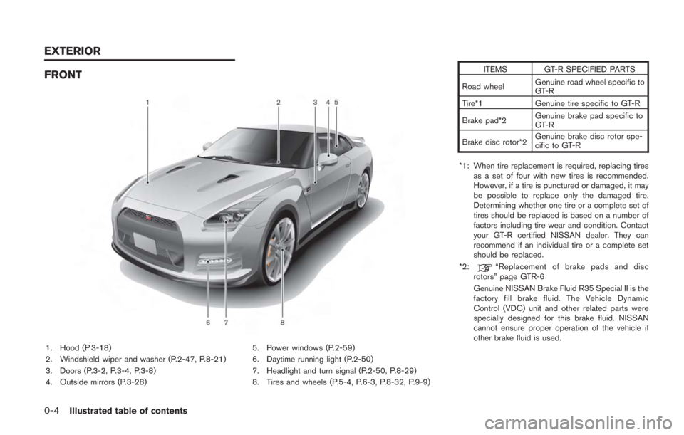
FRONT
1. Hood (P.3-18)
2. Windshield wiper and washer (P.2-47, P.8-21)
3. Doors (P.3-2, P.3-4, P.3-8)
4. Outside mirrors (P.3-28)5. Power windows (P.2-59)
6. Daytime running light (P.2-50)
7. Headlight and turn signal (P.2-50, P.8-29)
8. Tires and wheels (P.5-4, P.6-3, P.8-32, P.9-9) ITEMS GT-R SPECIFIED PARTS
Road wheel Genuine road wheel specific to
GT-R
Tire*1 Genuine tire specific to GT-R
Brake pad*2 Genuine brake pad specific to
GT-R
Brake disc rotor*2 Genuine brake disc rotor spe-
cific to GT-R
*1: When tire replacement is required, replacing tires as a set of four with new tires is recommended.
However, if a tire is punctured or damaged, it may
be possible to replace only the damaged tire.
Determining whether one tire or a complete set of
tires should be replaced is based on a number of
factors including tire wear and condition. Contact
your GT-R certified NISSAN dealer. They can
recommend if an individual tire or a complete set
should be replaced.
*2:
“Replacement of brake pads and disc
rotors” page GTR-6
Genuine NISSAN Brake Fluid R35 Special II is the
factory fill brake fluid. The Vehicle Dynamic
Control (VDC) unit and other related parts were
specially designed for this brake fluid. NISSAN
cannot ensure proper operation of the vehicle if
other brake fluid is used.
EXTERIOR
Page 43 of 354
0-6Illustrated table of contents
1. Coat hooks (P.2-59)
2. Inside lock knob (P.3-5)
3. Interior light control switch (P.2-62)
4. Map lights (P.2-62)
5. Sun visors (P.3-27)
6. Sunglasses holder (P.2-57)7. Inside rearview mirror (P.2-63, P.3-27)
8. Center console box (P.2-58)
— USB memory operation*
—iPod
®player operation*
9. Cup holders (P.2-56)
10. Power window switches (P.2-59) 11. Window lock button (P.2-60)
12. Power door lock switch (P.3-5)
*: Refer to the separate Multi Function Display
Owner’s Manual.
PASSENGER COMPARTMENT
Page 45 of 354
0-8Illustrated table of contents
1. Outside mirror control switch (P.3-28)
2. Center dial*
3. Audio system*
4. Heater and air conditioner*
5. Multi function display*
6. Hazard warning flasher switch (P.6-2)7. Glove box (P.2-58)
8. Fuse box cover (P.8-24)
9. Power outlet (P.2-54)
10. Rear window defroster switch (P.2-49)
11. Front passenger air bag status light (P.1-41)
12. Compact Disc slot*13. Trunk release power cancel switch (P.3-21)
*: Refer to the separate Multi Function Display
Owner’s Manual.
INSTRUMENT PANEL
Page 101 of 354
2-4Instruments and controls
1. Outside mirror control switch (P.3-28)
2. Center dial*
3. Audio system*
4. Heater and air conditioner*
5. Multi function display*
6. Hazard warning flasher switch (P.6-2)7. Glove box (P.2-58)
8. Fuse box cover (P.8-24)
9. Power outlet (P.2-54)
10. Rear window defroster switch (P.2-49)
11. Front passenger air bag status light (P.1-41)
12. Compact Disc slot*13. Trunk release power cancel switch (P.3-21)
*: Refer to the separate Multi Function Display
Owner’s Manual.
INSTRUMENT PANEL
Page 146 of 354
USING THE WASHER
Pull the lever toward you to operate the washer.
Then the wiper will also operate several times.
NOTE:
When the level of washer fluid is low, a
warning display appears on the vehicle
information display. (
“Low washer
fluid warning” page 2-41)
To defog/defrost the rear window, start the
engine and push the switch on. The indicator
light on the switch will come on. Push the switch
again to turn the defroster off.
It will automatically turn off in approximately 15
minutes.
NOTE:
When the rear window defroster switch is
pressed, the heated outside mirrors also
operate at the same time. (
“Outside
mirrors” page 3-28)
NOTICE
When cleaning the inner side of the rear
window, be careful not to scratch or
damage the rear window defroster.
Instruments and controls2-49
REAR WINDOW DEFROSTER
SWITCH
Page 160 of 354

seconds, then it turns off.
While the map light is on, if the ignition switch is
pushed to the ACC or ON position, or if the
driver’s side door is locked, the light turns off.
.When exiting the vehicle
When the ignition switch is pushed to the OFF
or LOCK position, the map lights turn on for
approximately 15 seconds, then it turns off.
If the driver’s side door is locked while the map
lights are on, the light turns off.
NOTE:
It is possible to cancel the key-linked
interior light control system setting. See
the separate Multi Function Display Own-
er’s Manual.
OFF position
When the switch is in the OFF position*3, the
map lights will not illuminate, regardless of any
condition.
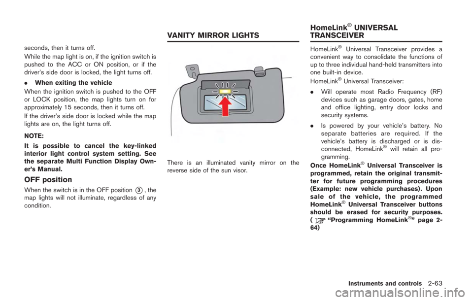
There is an illuminated vanity mirror on the
reverse side of the sun visor.
HomeLink®Universal Transceiver provides a
convenient way to consolidate the functions of
up to three individual hand-held transmitters into
one built-in device.
HomeLink
®Universal Transceiver:
. Will operate most Radio Frequency (RF)
devices such as garage doors, gates, home
and office lighting, entry door locks and
security systems.
. Is powered by your vehicle’s battery. No
separate batteries are required. If the
vehicle’s battery is discharged or is dis-
connected, HomeLink
®will retain all pro-
gramming.
Once HomeLink
®Universal Transceiver is
programmed, retain the original transmit-
ter for future programming procedures
(Example: new vehicle purchases) . Upon
sale of the vehicle, the programmed
HomeLink
®Universal Transceiver buttons
should be erased for security purposes.
(
“Programming HomeLink®” page 2-
64)
Instruments and controls2-63
VANITY MIRROR LIGHTS HomeLink
®UNIVERSAL
TRANSCEIVER
Page 166 of 354

3 Pre-driving checks and adjustments
Keys ........................................................................\
..................... 3-2Intelligent Key ...................................................................... 3-2
Doors ........................................................................\
................... 3-4
Locking with inside lock knob ........................................ 3-5
Locking with power door lock switch ........................... 3-5
Automatic door lock system ............................................ 3-5
Locking with mechanical key ........................................... 3-6
Opening the doors ............................................................ 3-7
Intelligent Key system ............................................................. 3-8 Intelligent Key functions .................................................... 3-9
Remote keyless entry functions ................................... 3-12
Setting hazard indicator and horn mode .................. 3-13
Warning signals ............................................................... 3-16
Troubleshooting guide ................................................... 3-17
Hood ........................................................................\
................. 3-18 Opening the hood ........................................................... 3-18
Closing the hood ............................................................. 3-19 Trunk ........................................................................\
................ 3-20
Trunk open request switch ......................................... 3-20
Trunk lid release switch ............................................... 3-20
Trunk release power cancel switch .......................... 3-21Opening and closing the trunk .................................. 3-21
Emergency trunk lid release ....................................... 3-22
Fuel-filler door ....................................................................... 3-23 Opening the fuel filler door ........................................ 3-24
Closing the fuel-filler door .......................................... 3-25
Steering wheel ...................................................................... 3-26
Tilt/telescopic steering column .................................. 3-26
Sun visors ........................................................................\
....... 3-27
Mirrors ........................................................................\
............. 3-27
Inside mirror .................................................................... 3-27
Outside mirrors .............................................................. 3-28
Vanity mirror .................................................................... 3-29
Page 192 of 354

Lower the sun visor to block sunlight coming
from the forward direction.
To block sunlight coming from the side, lower
the sun visor, then unclip it from the hook and
move it to the side.INSIDE MIRROR
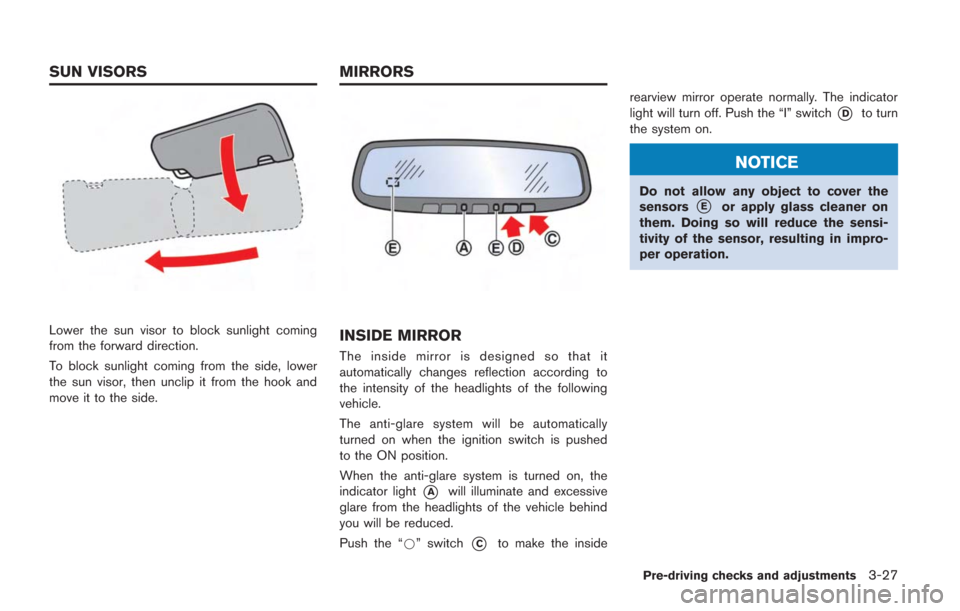
The inside mirror is designed so that it
automatically changes reflection according to
the intensity of the headlights of the following
vehicle.
The anti-glare system will be automatically
turned on when the ignition switch is pushed
to the ON position.
When the anti-glare system is turned on, the
indicator light
*Awill illuminate and excessive
glare from the headlights of the vehicle behind
you will be reduced.
Push the “*” switch
*Cto make the inside rearview mirror operate normally. The indicator
light will turn off. Push the “I” switch
*Dto turn
the system on.
NOTICE
Do not allow any object to cover the
sensors*Eor apply glass cleaner on
them. Doing so will reduce the sensi-
tivity of the sensor, resulting in impro-
per operation.
Pre-driving checks and adjustments3-27
SUN VISORS MIRRORS