2014 NISSAN GT-R reset
[x] Cancel search: resetPage 178 of 314
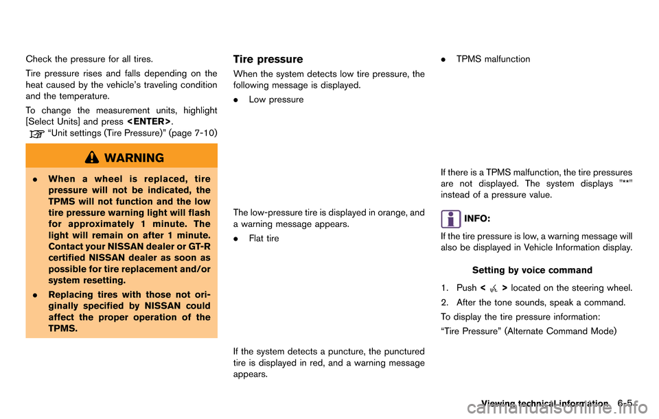
Check the pressure for all tires.
Tire pressure rises and falls depending on the
heat caused by the vehicle’s traveling condition
and the temperature.
To change the measurement units, highlight
[Select Units] and press
“Unit settings (Tire Pressure)” (page 7-10)
WARNING
.When a wheel is replaced, tire
pressure will not be indicated, the
TPMS will not function and the low
tire pressure warning light will flash
for approximately 1 minute. The
light will remain on after 1 minute.
Contact your NISSAN dealer or GT-R
certified NISSAN dealer as soon as
possible for tire replacement and/or
system resetting.
. Replacing tires with those not ori-
ginally specified by NISSAN could
affect the proper operation of the
TPMS.
Tire pressure
When the system detects low tire pressure, the
following message is displayed.
.Low pressure
The low-pressure tire is displayed in orange, and
a warning message appears.
.Flat tire
If the system detects a puncture, the punctured
tire is displayed in red, and a warning message
appears. .
TPMS malfunction
If there is a TPMS malfunction, the tire pressures
are not displayed. The system displays "**"
instead of a pressure value.
INFO:
If the tire pressure is low, a warning message will
also be displayed in Vehicle Information display.
Setting by voice command
1. Push <
>located on the steering wheel.
2. After the tone sounds, speak a command.
To display the tire pressure information:
“Tire Pressure” (Alternate Command Mode)
Viewing technical information6-5
Page 179 of 314
6-6Viewing technical information
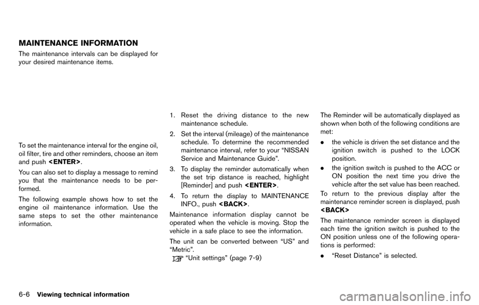
MAINTENANCE INFORMATION
The maintenance intervals can be displayed for
your desired maintenance items.
To set the maintenance interval for the engine oil,
oil filter, tire and other reminders, choose an item
and push
You can also set to display a message to remind
you that the maintenance needs to be per-
formed.
The following example shows how to set the
engine oil maintenance information. Use the
same steps to set the other maintenance
information.
1. Reset the driving distance to the new maintenance schedule.
2. Set the interval (mileage) of the maintenance schedule. To determine the recommended
maintenance interval, refer to your “NISSAN
Service and Maintenance Guide”.
3. To display the reminder automatically when the set trip distance is reached, highlight
[Reminder] and push
4. To return the display to MAINTENANCE INFO., push
Maintenance information display cannot be
operated when the vehicle is moving. Stop the
vehicle in a safe place to see the information.
The unit can be converted between “US” and
“Metric”.
“Unit settings” (page 7-9)
The Reminder will be automatically displayed as
shown when both of the following conditions are
met:
. the vehicle is driven the set distance and the
ignition switch is pushed to the LOCK
position.
. the ignition switch is pushed to the ACC or
ON position the next time you drive the
vehicle after the set value has been reached.
To return to the previous display after the
maintenance reminder screen is displayed, push
The maintenance reminder screen is displayed
each time the ignition switch is pushed to the
ON position unless one of the following opera-
tions is performed:
. “Reset Distance” is selected.
Page 233 of 314
![NISSAN GT-R 2014 R35 Multi Function Display Owners Manual 8-24Voice recognition
INFO:
With [Continuous Learning] set to on, the
system does not go back to the command
list screen, allowing to continue voice
command learning by the system.
12. If the system h NISSAN GT-R 2014 R35 Multi Function Display Owners Manual 8-24Voice recognition
INFO:
With [Continuous Learning] set to on, the
system does not go back to the command
list screen, allowing to continue voice
command learning by the system.
12. If the system h](/manual-img/5/367/w960_367-232.png)
8-24Voice recognition
INFO:
With [Continuous Learning] set to on, the
system does not go back to the command
list screen, allowing to continue voice
command learning by the system.
12. If the system has learned the command correctly, “None” will change to “Stored”.
Editing registered items
It is possible to edit user names and select
learning function settings.
1. Push
2. Highlight [Others] and push
3. Highlight [Voice Recognition] and push
4. Highlight [Speaker Adaptation] and push
5. Highlight a user to edit, and push
6. Highlight [Setting] and push
7. Highlight an item to edit, and push
Setting items
.[Edit User Name]:
Edit the user name.
.[Delete Voice Data]:Reset the user voice that the voice
recognition system has learned.
.[Continuous Learning]:Have the system learn the voice com-
mands of the user in succession, without
selecting commands one by one.
VOICE COMMAND EXAMPLES
To use the voice recognition function, speaking
one command is sometimes sufficient, but at
other times it is necessary to speak two or more
commands. As examples, some additional basic
operations by voice commands are described
here.
Page 254 of 314
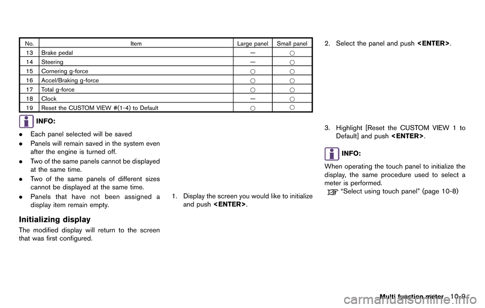
No.Item Large panel Small panel
13 Brake pedal —*
14 Steering —*
15 Cornering g-force **
16 Accel/Braking g-force **
17 Total g-force **
18 Clock —*
19 Reset the CUSTOM VIEW #(1-4) to Default **
INFO:
. Each panel selected will be saved
. Panels will remain saved in the system even
after the engine is turned off.
. Two of the same panels cannot be displayed
at the same time.
. Two of the same panels of different sizes
cannot be displayed at the same time.
. Panels that have not been assigned a
display item remain empty.
Initializing display
The modified display will return to the screen
that was first configured.
1. Display the screen you would like to initialize
and push
2. Select the panel and push
3. Highlight [Reset the CUSTOM VIEW 1 to
Default] and push
INFO:
When operating the touch panel to initialize the
display, the same procedure used to select a
meter is performed.
“Select using touch panel” (page 10-8)
Multi function meter10-9
Page 263 of 314
10-18Multi function meter
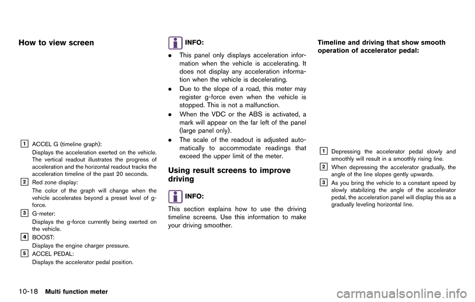
How to view screen
&1ACCEL G (timeline graph):
Displays the acceleration exerted on the vehicle.
The vertical readout illustrates the progress of
acceleration and the horizontal readout tracks the
acceleration timeline of the past 20 seconds.
&2Red zone display:
The color of the graph will change when the
vehicle accelerates beyond a preset level of g-
force.
&3G-meter:
Displays the g-force currently being exerted on
the vehicle.
&41BOOST:
Displays the engine charger pressure.
&5ACCEL PEDAL:
Displays the accelerator pedal position.
INFO:
. This panel only displays acceleration infor-
mation when the vehicle is accelerating. It
does not display any acceleration informa-
tion when the vehicle is decelerating.
. Due to the slope of a road, this meter may
register g-force even when the vehicle is
stopped. This is not a malfunction.
. When the VDC or the ABS is activated, a
mark will appear on the far left of the panel
(large panel only).
. The scale of the readout is adjusted auto-
matically to accommodate readings that
exceed the upper limit of the meter.
Using result screens to improve
driving
INFO:
This section explains how to use the driving
timeline screens. Use this information to make
your driving smoother. Timeline and driving that show smooth
operation of accelerator pedal:
&1Depressing the accelerator pedal slowly and
smoothly will result in a smoothly rising line.
&2When depressing the accelerator gradually, the
angle of the line slopes gently upwards.
&3As you bring the vehicle to a constant speed by
slowly stabilizing the angle of the accelerator
pedal, the acceleration panel will display this as a
gradually leveling horizontal line.
Page 264 of 314
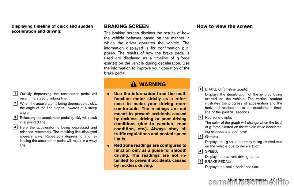
Displaying timeline of quick and sudden
acceleration and driving:
&1Quickly depressing the accelerator pedal will
result in a steep climbing line.
&2When the accelerator is being depressed quickly,
the angle of the line slopes upwards at a steep
angle.
&3Releasing the accelerator pedal quickly will result
in a pointed line
&4Here the accelerator is being depressed and
released repeatedly. The resulting line displayed
appears wavy. Repeatedly depressing and re-
leasing the accelerator pedal will result in a wavy
line.
BRAKING SCREEN
The braking screen displays the results of how
the vehicle behaves based on the manner in
which the driver operates the vehicle. The
information displayed is for confirmation pur-
poses. The results of how the brake pedal is
used are displayed as a timeline of g-force
exerted on the vehicle during deceleration. Use
the information to improve your operation of the
brake pedal.
WARNING
.Use the information from the multi
function meter strictly as a refer-
ence to make your driving more
comfortable. The readings are not
meant to prevent accidents caused
by reckless driving or poor driving
conditions (due to weather, road
condition, etc.) . Always obey all
traffic regulations and posted speed
limits.
. Red zone readings are configured to
function only as a guide for smooth
driving. The readings are not in-
tended to prevent accidents caused
by reckless driving.
How to view the screen
&1BRAKE G (timeline graph):
Displays the deceleration of the g-force being
exerted on the vehicle. The vertical readout
illustrates the progress of acceleration and the
horizontal readout tracks the deceleration time-
line of the past 20 seconds.
&2Red zone display:
The color of the graph will change when the level
of g-force exerted on the vehicle while decelerat-
ing exceeds a preset level.
&3G-meter:
Displays the g-force currently being exerted due
on the vehicle due to deceleration.
&4SPEED:
Displays the current driving speed.
&5BRAKE PEDAL:
Displays the brake pedal position.
Multi function meter10-19
Page 266 of 314
STEERING SCREEN
The steering screen allows you to confirm how
the vehicle responds to your driving by display-
ing the results of how you operate the vehicle.
The results of your driving are displayed as a
timeline of the g-force exerted on the vehicle.
Use the displayed information to improve your
steering smoothness.
WARNING
.Use the information from the multi
function meter strictly as a refer-
ence to make your driving more
comfortable. The readings are not
meant to prevent accidents caused
by reckless driving or poor driving
conditions (due to weather, road
condition, etc.) . Always obey all
traffic regulations and posted speed
limits.
. Red zone readings are configured to
function only as a guide for smooth
driving. The readings are not in-
tended to prevent accidents caused
by reckless driving.
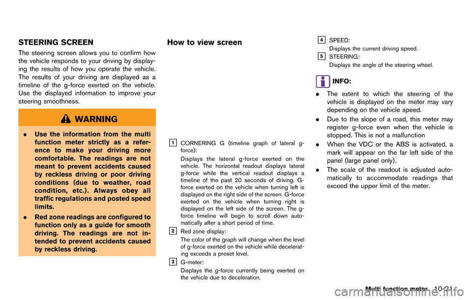
How to view screen
&1CORNERING G (timeline graph of lateral g-
force):
Displays the lateral g-force exerted on the
vehicle. The horizontal readout displays lateral
g-force while the vertical readout displays a
timeline of the past 20 seconds of driving. G-
force exerted on the vehicle when turning left is
displayed on the right side of the screen. G-force
exerted on the vehicle when turning right is
displayed on the left side of the screen. The g-
force timeline will begin to scroll down auto-
matically after a short period of time.
&2Red zone display:
The color of the graph will change when the level
of g-force exerted on the vehicle while decelerat-
ing exceeds a preset level.
&3G-meter:
Displays the g-force currently being exerted on
the vehicle due to deceleration.
&4SPEED:
Displays the current driving speed.
&5STEERING:
Displays the angle of the steering wheel.
INFO:
. The extent to which the steering of the
vehicle is displayed on the meter may vary
depending on the vehicle speed.
. Due to the slope of a road, this meter may
register g-force even when the vehicle is
stopped. This is not a malfunction
. When the VDC or the ABS is activated, a
mark will appear on the far left side of the
panel (large panel only) .
. The scale of the readout is adjusted auto-
matically to accommodate readings that
exceed the upper limit of the meter.
Multi function meter10-21
Page 271 of 314
10-26Multi function meter
INFO:
. The STOP WATCH function can only be
used when the clock is activated.
. If using the driver’s notes, the STOP
WATCH function is unavailable. To use the
STOP WATCH function, first finish using the
driver’s notes.
. If the ignition is in the OFF position, you will
not be able to use the STOP WATCH
function.
. If the ignition is put into the ACC or the OFF
position while using the timer, timing will
end.
. The timer will continue timing while you
display other screens until you push
. The maximum time that the system timer can
display is a recorded time of up to 9 hours
59 minutes and 59.99 seconds.
. When timing has finished, the upper timer
will reset to 00:00.0
. When the recorded time and the finished
recording time are displayed, they tempora-
rily interrupt the time recorder display and
are displayed in large numbers. The re-
corded time will disappear automatically
after 5-10 seconds. .
When screens other than the multi function
meter are displayed, the STOP WATCH
screen will not interrupt the display.
Checking timed distance list
You can review the list of past measured times.
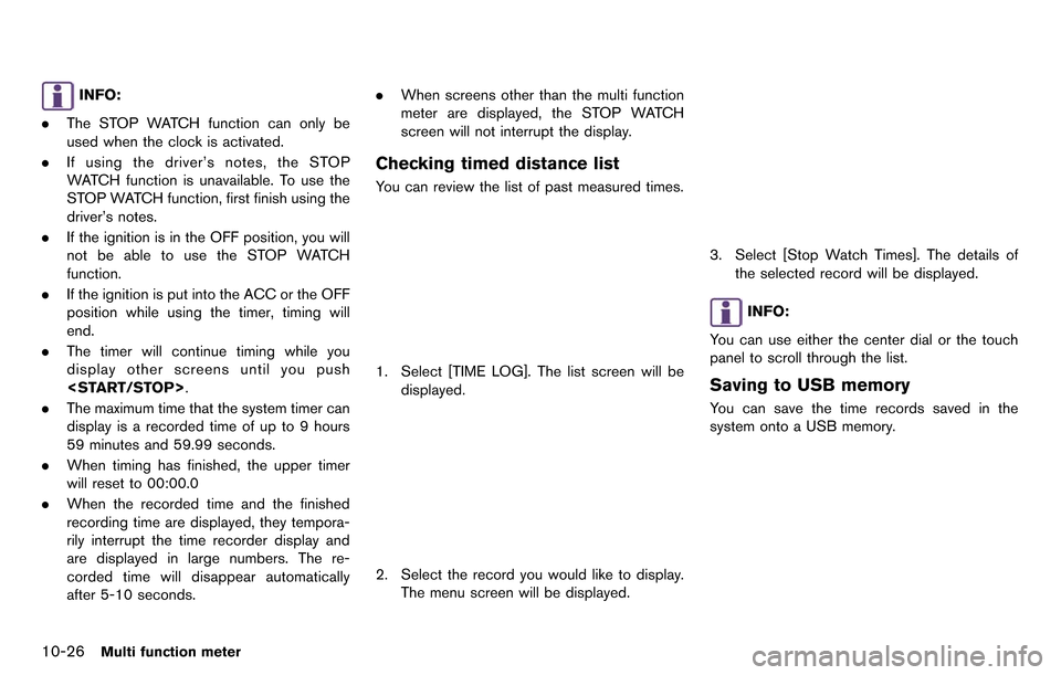
1. Select [TIME LOG]. The list screen will be
displayed.
2. Select the record you would like to display.
The menu screen will be displayed.
3. Select [Stop Watch Times]. The details ofthe selected record will be displayed.
INFO:
You can use either the center dial or the touch
panel to scroll through the list.
Saving to USB memory
You can save the time records saved in the
system onto a USB memory.