2014 NISSAN CUBE warning light
[x] Cancel search: warning lightPage 72 of 332
rails. The side air bags and curtain air bags
inflate quickly in order to help protect the
occupants in the outboard seating positions.
Because of this, the force of the side air bags
and curtain air bags inflating can increase the
risk of injury if the occupant is too close to, or is
against, these air bag modules during inflation.
The side air bags and curtain air bags will deflate
quickly after the collision is over.
The side air bags and curtain air bags
operate only when the ignition switch is in
the ON position.
After placing the ignition switch in the ON
position, the supplemental air bag warning
light illuminates. The supplemental air bag
warning light will turn off after about 7
seconds if the systems are operational.
WARNING
.Do not place any objects near the
seatback of the front seats. Also, do
not place any objects (an umbrella,
bag, etc.) between the front door
finisher and the front seat. Such
objects may become dangerous
projectiles and cause injury if a side
air bag inflates. .
Right after inflation, several side air
bag and curtain air bag system
components will be hot. Do not
touch them; you may severely burn
yourself.
. No unauthorized changes should be
made to any components or wiring
of the side air bag and curtain air
bag systems. This is to prevent
damage to or accidental inflation
of the side air bag and curtain air
bag systems.
. Do not make unauthorized changes
to your vehicle’s electrical system,
suspension system or side panel.
This could affect proper operation
of the side air bag and curtain air
bag systems.
. Tampering with the side air bag
system may result in serious perso-
nal injury. For example, do not
change the front seats by placing
material near the seatbacks or by
installing additional trim material,
such as seat covers, around the side
air bag.
. Work around and on the side air bag
and curtain air bag systems should
be done by a NISSAN dealer. In- stallation of electrical equipment
should also be done by a NISSAN
dealer. The Supplemental Restraint
System (SRS) wiring harnesses*
should not be modified or discon-
nected. Unauthorized electrical test
equipment and probing devices
should not be used on the side air
bag and curtain supplemental air
bag systems.
*The SRS wiring harness connectors are
yellow and orange for easy identification.
When selling your vehicle, we request that you
inform the buyer about the side air bag and
curtain air bag systems and guide the buyer to
the appropriate sections in this Owner’s Manual.
SEAT BELTS WITH PRETENSIONERS
(front seats)
WARNING
. The pretensioners cannot be reused
after activation. They must be re-
placed together with the retractor
and buckle as a unit.
. If the vehicle becomes involved in a
collision but a pretensioner is not
Safety — Seats, seat belts and supplemental restraint system1-53
Page 73 of 332
1-54Safety — Seats, seat belts and supplemental restraint system
activated, be sure to have the pre-
tensioner system checked and, if
necessary, replaced by a NISSAN
dealer.
. No unauthorized changes should be
made to any components or wiring
of the pretensioner system. This is
to prevent damage to or accidental
activation of the pretensioners.
Tampering with the pretensioner
system may result in serious perso-
nal injury.
. Work around and on the preten-
sioner system should be done by a
NISSAN dealer. Installation of elec-
trical equipment should also be
done by a NISSAN dealer. Un-
authorized electrical test equipment
and probing devices should not be
used on the pretensioner system.
. If you need to dispose of a preten-
sioner or scrap the vehicle, contact a
NISSAN dealer. Correct preten-
sioner disposal procedures are set
forth in the appropriate NISSAN
Service Manual. Incorrect disposal
procedures could cause personal
injury. The pretensioner system may activate with the
supplemental air bag system in certain types of
collisions. Working with the seat belt retractor, it
helps tighten the seat belt when the vehicle
becomes involved in certain types of collisions,
helping to restrain front seat occupants.
The pretensioner is encased with the seat belt
retractor. These seat belts are used the same
way as conventional seat belts.
When a pretensioner activates, smoke is re-
leased and a loud noise may be heard. The
smoke is not harmful and does not indicate a
fire. Care should be taken not to inhale it, as it
may cause irritation and choking. Those with a
history of a breathing condition should get fresh
air promptly.
After pretensioner activation, load limiters allow
the seat belt to release webbing (if necessary) to
reduce forces against the chest.
The supplemental air bag warning light
is
used to indicate malfunctions in the pretensioner
system. (See “Supplemental air bag warning
light” (P.1-55) for more details.) If the operation
of the supplemental air bag warning light
indicates there is a malfunction, have the system
checked by a NISSAN dealer.
When selling your vehicle, we request that you
inform the buyer about the pretensioner system
and guide the buyer to the appropriate sections in this Owner’s Manual.
SUPPLEMENTAL AIR BAG WARNING
LABELS
Warning labels about the supplemental front-
impact air bag system are placed in the vehicle
as shown in the illustration.
Page 74 of 332
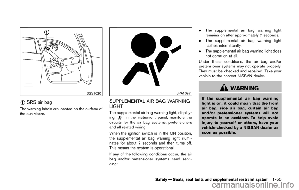
SSS1020
*1SRS air bag
The warning labels are located on the surface of
the sun visors.
SPA1097
SUPPLEMENTAL AIR BAG WARNING
LIGHT
The supplemental air bag warning light, display-
ingin the instrument panel, monitors the
circuits for the air bag systems, pretensioners
and all related wiring.
When the ignition switch is in the ON position,
the supplemental air bag warning light illumi-
nates for about 7 seconds and then turns off.
This means the system is operational.
If any of the following conditions occur, the air
bag and/or pretensioner systems need servi-
cing: .
The supplemental air bag warning light
remains on after approximately 7 seconds.
. The supplemental air bag warning light
flashes intermittently.
. The supplemental air bag warning light does
not come on at all.
Under these conditions, the air bag and/or
pretensioner systems may not operate properly.
They must be checked and repaired. Take your
vehicle to the nearest NISSAN dealer.
WARNING
If the supplemental air bag warning
light is on, it could mean that the front
air bag, side air bag, curtain air bag
and/or pretensioner systems will not
operate in an accident. To help avoid
injury to yourself or others, have your
vehicle checked by a NISSAN dealer as
soon as possible.
Safety — Seats, seat belts and supplemental restraint system1-55
Page 75 of 332
1-56Safety — Seats, seat belts and supplemental restraint system
REPAIR AND REPLACEMENT PRO-
CEDURE
The front air bags, side air bags, curtain air bags
and pretensioners are designed to activate on a
one-time-only basis. As a reminder, unless it is
damaged, the supplemental air bag warning light
will remain illuminated after inflation has oc-
curred. Repair and replacement of these sys-
tems should be done only by a NISSAN dealer.
When maintenance work is required on the
vehicle, the front air bags, side air bags, curtain
air bags and pretensioners and related parts
should be pointed out to the person performing
the maintenance. The ignition switch should
always be in the LOCK position when working
under the hood or inside the vehicle.
WARNING
.Once a front air bag, side air bag or
curtain air bag has inflated, the air
bag module will not function again
and must be replaced. Additionally,
the activated pretensioners must
also be replaced. The air bag mod-
ule and pretensioner should be
replaced by a NISSAN dealer. The
air bag modules and pretensioner
system cannot be repaired. .
The front air bag, side air bag and
curtain air bag systems, and preten-
sioner system should be inspected
by a NISSAN dealer if there is any
damage to the front end or side
portion of the vehicle.
. If you need to dispose of a supple-
mental air bag or pretensioner or
scrap the vehicle, contact a NISSAN
dealer. Correct supplemental air
bag and pretensioner system dis-
posal procedures are set forth in the
appropriate NISSAN Service Man-
ual. Incorrect disposal procedures
could cause personal injury.
Page 76 of 332
2 Instruments and controls
Cockpit ........................................................................\
................ 2-2
Instrument panel ........................................................................\
2-3
Meters and gauges ................................................................... 2-4
Speedometer and odometer ............................................ 2-5
Tachometer ........................................................................\
... 2-7
Engine coolant temperature gauge ................................ 2-7
Fuel gauge ........................................................................\
.... 2-8
Vehicle information display ................................................ 2-8
Outside air temperature (if so equipped) ..................... 2-9
Continuously Variable Transmission (CVT) position
indicator (if so equipped) .................................................. 2-9
Trip computer ....................................................................... 2-9
Warning/indicator lights and audible reminders ............ 2-11
Checking bulbs ................................................................. 2-12
Warning lights ................................................................... 2-12
Indicator lights ................................................................... 2-16
Audible reminders ............................................................ 2-18
Security systems .................................................................... 2-19 Vehicle security system .................................................. 2-19
NISSAN Vehicle Immobilizer System .......................... 2-20
Windshield wiper and washer switch ............................... 2-22
Rear window wiper and washer switch ........................... 2-23 Rear window defroster switch ........................................... 2-24
Headlight and turn signal switch ....................................... 2-24
Headlight switch ............................................................ 2-24
Turn signal switch .......................................................... 2-27
Fog light switch (if so equipped) .............................. 2-27
Horn ........................................................................\
.................. 2-28
Vehicle Dynamic Control (VDC) OFF switch ................. 2-28
Power outlet ........................................................................\
.... 2-28
Storage ........................................................................\
............ 2-29 Cup holders ..................................................................... 2-29
Glove box ........................................................................\
. 2-31
Rear pillar pocket ........................................................... 2-32
Luggage hooks ............................................................... 2-32
Utility hooks ..................................................................... 2-33
Windows ........................................................................\
......... 2-33 Power windows .............................................................. 2-33
Interior lights ........................................................................\
.. 2-36 Map lights ........................................................................\
2-36
Map light control switch ............................................... 2-36
Ceiling light ...................................................................... 2-37
Cargo light ........................................................................\
...... 2-38>
Page 78 of 332
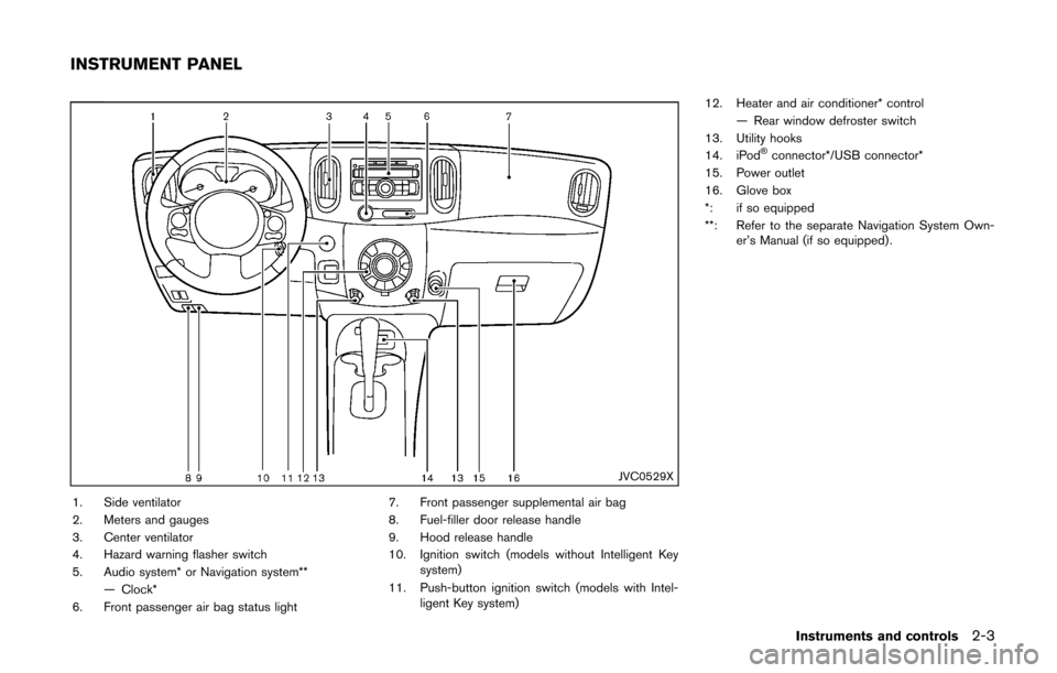
JVC0529X
1. Side ventilator
2. Meters and gauges
3. Center ventilator
4. Hazard warning flasher switch
5. Audio system* or Navigation system**— Clock*
6. Front passenger air bag status light 7. Front passenger supplemental air bag
8. Fuel-filler door release handle
9. Hood release handle
10. Ignition switch (models without Intelligent Key
system)
11. Push-button ignition switch (models with Intel- ligent Key system) 12. Heater and air conditioner* control
— Rear window defroster switch
13. Utility hooks
14. iPod
®connector*/USB connector*
15. Power outlet
16. Glove box
*: if so equipped
**: Refer to the separate Navigation System Own- er’s Manual (if so equipped) .
Instruments and controls2-3
INSTRUMENT PANEL
Page 79 of 332
2-4Instruments and controls
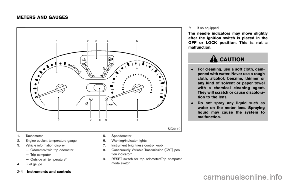
SIC4119
1. Tachometer
2. Engine coolant temperature gauge
3. Vehicle information display— Odometer/twin trip odometer
— Trip computer
— Outside air temperature*
4. Fuel gauge 5. Speedometer
6. Warning/indicator lights
7. Instrument brightness control knob
8. Continuously Variable Transmission (CVT) posi-
tion indicator*
9. RESET switch for trip odometer/Trip computer mode switch *: if so equipped
The needle indicators may move slightly
after the ignition switch is placed in the
OFF or LOCK position. This is not a
malfunction.
CAUTION
.
For cleaning, use a soft cloth, dam-
pened with water. Never use a rough
cloth, alcohol, benzine, thinner or
any kind of solvent or paper towel
with a chemical cleaning agent.
They will scratch or cause discolora-
tion to the lens.
. Do not spray any liquid such as
water on the meter lens. Spraying
liquid may cause the system to
malfunction.
METERS AND GAUGES
Page 81 of 332
2-6Instruments and controls
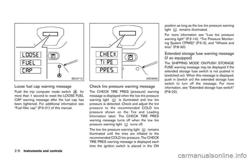
SIC4712
Loose fuel cap warning message
Push the trip computer mode switch*Afor
more than 1 second to reset the LOOSE FUEL
CAP warning message after the fuel cap has
been tightened. For additional information see
“Fuel-filler cap” (P.3-21) of this manual.
JVI0359X
Check tire pressure warning message
The CHECK TIRE PRES (pressure) warning
message is displayed when the low tire pressure
warning light
is illuminated and low tire
pressure is detected. Check and adjust the tire
pressure to the recommended COLD tire
pressure shown on the Tire and Loading
Information label. The CHECK TIRE PRES
warning message turns off when the low tire
pressure warning light
turns off.
The low tire pressure warning light
remains
illuminated until the tires are inflated to the
recommended COLD tire pressure. The CHECK
TIRE PRES warning message is displayed each
time the ignition switch is placed in the ON position as long as the low tire pressure warning
light
remains illuminated.
For more information see “Low tire pressure
warning light” (P.2-14) , “Tire Pressure Monitor-
ing System (TPMS)” (P.5-3) , and “Wheels and
tires” (P.8-30).
Extended storage fuse warning message
(if so equipped)
The SHIPPING MODE ON/PUSH STORAGE
FUSE warning message may be displayed if the
extended storage fuse switch is not pushed in
(switched on) . When this message is displayed,
push in (switch on) the extended storage fuse
switch to turn off the message. For more
information, see “Extended storage fuse switch”
(P.8-22) .