Page 74 of 332
SSS1020
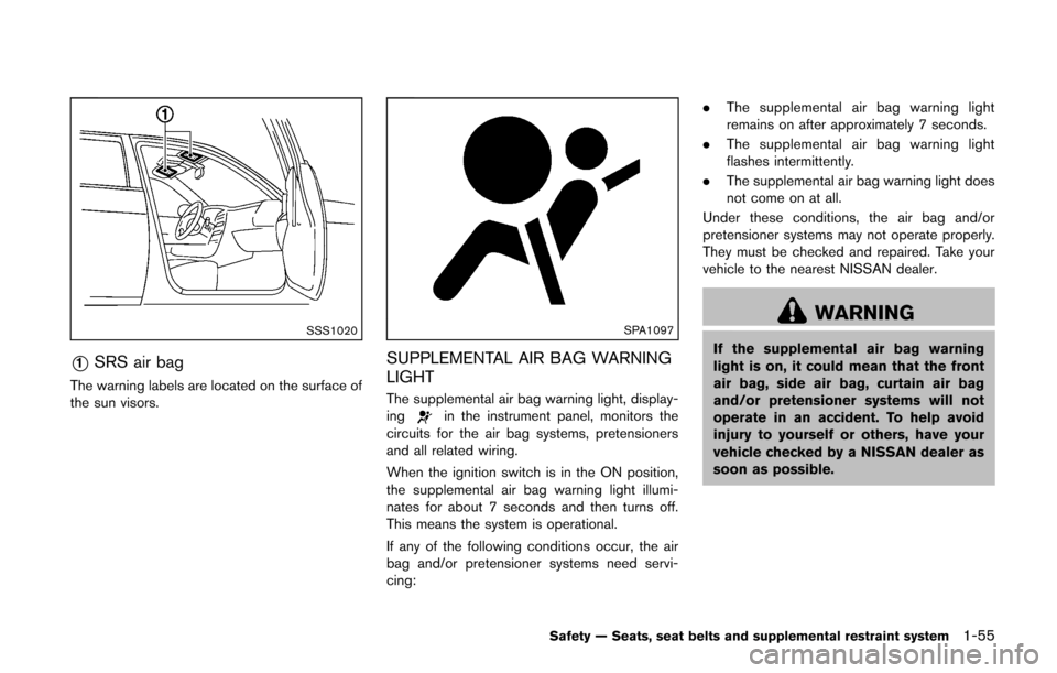
*1SRS air bag
The warning labels are located on the surface of
the sun visors.
SPA1097
SUPPLEMENTAL AIR BAG WARNING
LIGHT
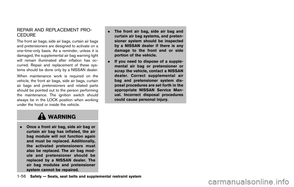
The supplemental air bag warning light, display-
ingin the instrument panel, monitors the
circuits for the air bag systems, pretensioners
and all related wiring.
When the ignition switch is in the ON position,
the supplemental air bag warning light illumi-
nates for about 7 seconds and then turns off.
This means the system is operational.
If any of the following conditions occur, the air
bag and/or pretensioner systems need servi-
cing: .
The supplemental air bag warning light
remains on after approximately 7 seconds.
. The supplemental air bag warning light
flashes intermittently.
. The supplemental air bag warning light does
not come on at all.
Under these conditions, the air bag and/or
pretensioner systems may not operate properly.
They must be checked and repaired. Take your
vehicle to the nearest NISSAN dealer.
WARNING
If the supplemental air bag warning
light is on, it could mean that the front
air bag, side air bag, curtain air bag
and/or pretensioner systems will not
operate in an accident. To help avoid
injury to yourself or others, have your
vehicle checked by a NISSAN dealer as
soon as possible.
Safety — Seats, seat belts and supplemental restraint system1-55
Page 75 of 332
1-56Safety — Seats, seat belts and supplemental restraint system
REPAIR AND REPLACEMENT PRO-
CEDURE
The front air bags, side air bags, curtain air bags
and pretensioners are designed to activate on a
one-time-only basis. As a reminder, unless it is
damaged, the supplemental air bag warning light
will remain illuminated after inflation has oc-
curred. Repair and replacement of these sys-
tems should be done only by a NISSAN dealer.
When maintenance work is required on the
vehicle, the front air bags, side air bags, curtain
air bags and pretensioners and related parts
should be pointed out to the person performing
the maintenance. The ignition switch should
always be in the LOCK position when working
under the hood or inside the vehicle.
WARNING
.Once a front air bag, side air bag or
curtain air bag has inflated, the air
bag module will not function again
and must be replaced. Additionally,
the activated pretensioners must
also be replaced. The air bag mod-
ule and pretensioner should be
replaced by a NISSAN dealer. The
air bag modules and pretensioner
system cannot be repaired. .
The front air bag, side air bag and
curtain air bag systems, and preten-
sioner system should be inspected
by a NISSAN dealer if there is any
damage to the front end or side
portion of the vehicle.
. If you need to dispose of a supple-
mental air bag or pretensioner or
scrap the vehicle, contact a NISSAN
dealer. Correct supplemental air
bag and pretensioner system dis-
posal procedures are set forth in the
appropriate NISSAN Service Man-
ual. Incorrect disposal procedures
could cause personal injury.
Page 78 of 332
JVC0529X
1. Side ventilator
2. Meters and gauges
3. Center ventilator
4. Hazard warning flasher switch
5. Audio system* or Navigation system**— Clock*
6. Front passenger air bag status light 7. Front passenger supplemental air bag
8. Fuel-filler door release handle
9. Hood release handle
10. Ignition switch (models without Intelligent Key
system)
11. Push-button ignition switch (models with Intel- ligent Key system) 12. Heater and air conditioner* control
— Rear window defroster switch
13. Utility hooks
14. iPod
®connector*/USB connector*
15. Power outlet
16. Glove box
*: if so equipped
**: Refer to the separate Navigation System Own- er’s Manual (if so equipped) .
Instruments and controls2-3
INSTRUMENT PANEL
Page 79 of 332
2-4Instruments and controls
SIC4119
1. Tachometer
2. Engine coolant temperature gauge
3. Vehicle information display— Odometer/twin trip odometer
— Trip computer
— Outside air temperature*
4. Fuel gauge 5. Speedometer
6. Warning/indicator lights
7. Instrument brightness control knob
8. Continuously Variable Transmission (CVT) posi-
tion indicator*
9. RESET switch for trip odometer/Trip computer mode switch *: if so equipped
The needle indicators may move slightly
after the ignition switch is placed in the
OFF or LOCK position. This is not a
malfunction.
CAUTION
.
For cleaning, use a soft cloth, dam-
pened with water. Never use a rough
cloth, alcohol, benzine, thinner or
any kind of solvent or paper towel
with a chemical cleaning agent.
They will scratch or cause discolora-
tion to the lens.
. Do not spray any liquid such as
water on the meter lens. Spraying
liquid may cause the system to
malfunction.
METERS AND GAUGES
Page 80 of 332
SIC4120Speedometer
SPEEDOMETER AND ODOMETER
Speedometer
The speedometer indicates vehicle speed in
miles per hour (MPH) and kilometers per hour
(km/h) .
SIC4121Odometer/twin trip odometer
Odometer/twin trip odometer
The odometer*1/twin trip odometer*2are
displayed when the ignition switch is in the ON
position.
The odometer records the total distance the
vehicle has been driven.
The twin trip odometer records the distance of
individual trips.
Changing the display:
Pushing the reset switch
*3located on the
meter panel changes the display as follows:
TRIP A ?TRIP B ?Trip computer mode ?
TRIP A For trip computer information, see “Trip compu-
ter” (P.2-9) .
Resetting the trip odometer:
Pushing the reset switch
*3for approximately 1
second resets the trip odometer to zero.
Instruments and controls2-5
Page 81 of 332
2-6Instruments and controls
SIC4712
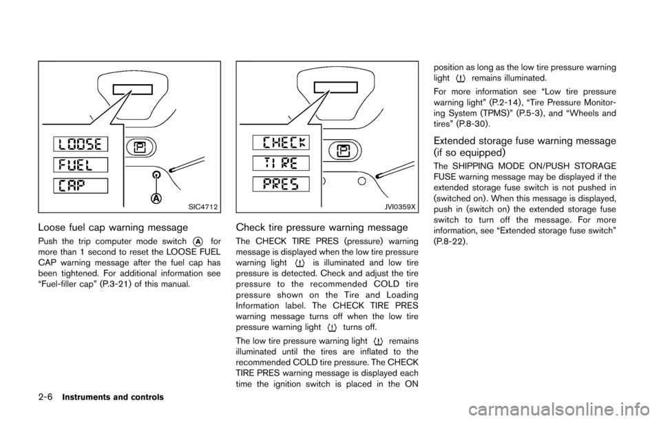
Loose fuel cap warning message
Push the trip computer mode switch*Afor
more than 1 second to reset the LOOSE FUEL
CAP warning message after the fuel cap has
been tightened. For additional information see
“Fuel-filler cap” (P.3-21) of this manual.
JVI0359X
Check tire pressure warning message
The CHECK TIRE PRES (pressure) warning
message is displayed when the low tire pressure
warning light
is illuminated and low tire
pressure is detected. Check and adjust the tire
pressure to the recommended COLD tire
pressure shown on the Tire and Loading
Information label. The CHECK TIRE PRES
warning message turns off when the low tire
pressure warning light
turns off.
The low tire pressure warning light
remains
illuminated until the tires are inflated to the
recommended COLD tire pressure. The CHECK
TIRE PRES warning message is displayed each
time the ignition switch is placed in the ON position as long as the low tire pressure warning
light
remains illuminated.
For more information see “Low tire pressure
warning light” (P.2-14) , “Tire Pressure Monitor-
ing System (TPMS)” (P.5-3) , and “Wheels and
tires” (P.8-30).
Extended storage fuse warning message
(if so equipped)
The SHIPPING MODE ON/PUSH STORAGE
FUSE warning message may be displayed if the
extended storage fuse switch is not pushed in
(switched on) . When this message is displayed,
push in (switch on) the extended storage fuse
switch to turn off the message. For more
information, see “Extended storage fuse switch”
(P.8-22) .
Page 83 of 332
2-8Instruments and controls
SIC4124
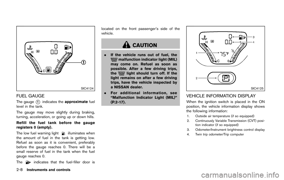
FUEL GAUGE
The gauge*1indicates theapproximate fuel
level in the tank.
The gauge may move slightly during braking,
turning, acceleration, or going up or down hills.
Refill the fuel tank before the gauge
registers 0 (empty) .
The low fuel warning light
illuminates when
the amount of fuel in the tank is getting low.
Refuel as soon as it is convenient, preferably
before the gauge reaches 0. There will be a
small reserve of fuel in the tank when the fuel
gauge reaches 0.
The
indicates that the fuel-filler door is located on the front passenger’s side of the
vehicle.
CAUTION
.
If the vehicle runs out of fuel, themalfunction indicator light (MIL)
may come on. Refuel as soon as
possible. After a few driving trips,
the
light should turn off. If the
light remains on after a few driving
trips, have the vehicle inspected by
a NISSAN dealer.
. For additional information, see
“Malfunction Indicator Light (MIL)”
(P.2-17) .
SIC4125
VEHICLE INFORMATION DISPLAY
When the ignition switch is placed in the ON
position, the vehicle information display shows
the following information:
1. Outside air temperature (if so equipped)
2. Continuously Variable Transmission (CVT) posi-
tion indicator (if so equipped)
3. Odometer/Instrument brightness control display
4. Twin trip odometer/Trip computer
Page 84 of 332
OUTSIDE AIR TEMPERATURE (if so
equipped)
The outside air temperature is displayed in8F.
When the outside air temperature becomes
378F(3 8C) or lower, the outside air temperature
display blinks to give a warning. The display will
stop blinking after 1 minute or when the outside
air temperature becomes 398F(4 8C) or above.
The display may differ from the actual outside
temperature displayed on various signs or bill-
boards.
CONTINUOUSLY VARIABLE TRANS-
MISSION (CVT) POSITION INDICATOR
(if so equipped)
The Continuously Variable Transmission (CVT)
position indicator indicates the shift lever posi-
tion when the ignition switch is in the ON
position.
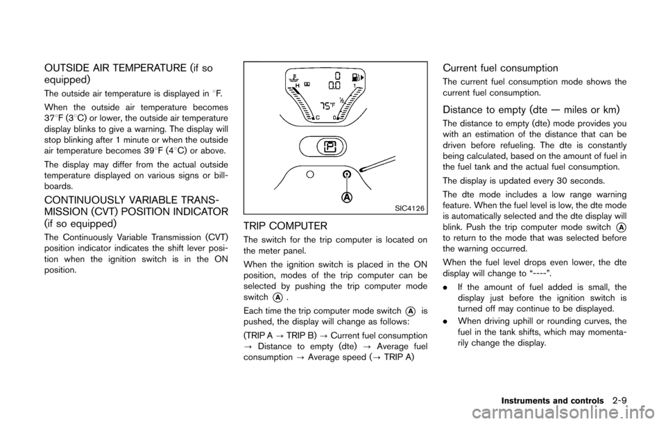
SIC4126
TRIP COMPUTER
The switch for the trip computer is located on
the meter panel.
When the ignition switch is placed in the ON
position, modes of the trip computer can be
selected by pushing the trip computer mode
switch
*A.
Each time the trip computer mode switch
*Ais
pushed, the display will change as follows:
(TRIP A ?TRIP B) ?Current fuel consumption
? Distance to empty (dte) ?Average fuel
consumption ?Average speed (? TRIP A)
Current fuel consumption
The current fuel consumption mode shows the
current fuel consumption.
Distance to empty (dte — miles or km)
The distance to empty (dte) mode provides you
with an estimation of the distance that can be
driven before refueling. The dte is constantly
being calculated, based on the amount of fuel in
the fuel tank and the actual fuel consumption.
The display is updated every 30 seconds.
The dte mode includes a low range warning
feature. When the fuel level is low, the dte mode
is automatically selected and the dte display will
blink. Push the trip computer mode switch
*Ato return to the mode that was selected before
the warning occurred.
When the fuel level drops even lower, the dte
display will change to “----”.
.If the amount of fuel added is small, the
display just before the ignition switch is
turned off may continue to be displayed.
. When driving uphill or rounding curves, the
fuel in the tank shifts, which may momenta-
rily change the display.
Instruments and controls2-9