2014 NISSAN CUBE display
[x] Cancel search: displayPage 84 of 332
OUTSIDE AIR TEMPERATURE (if so
equipped)
The outside air temperature is displayed in8F.
When the outside air temperature becomes
378F(3 8C) or lower, the outside air temperature
display blinks to give a warning. The display will
stop blinking after 1 minute or when the outside
air temperature becomes 398F(4 8C) or above.
The display may differ from the actual outside
temperature displayed on various signs or bill-
boards.
CONTINUOUSLY VARIABLE TRANS-
MISSION (CVT) POSITION INDICATOR
(if so equipped)
The Continuously Variable Transmission (CVT)
position indicator indicates the shift lever posi-
tion when the ignition switch is in the ON
position.
SIC4126
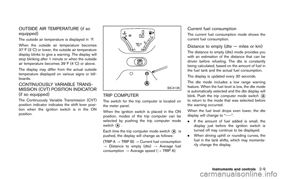
TRIP COMPUTER
The switch for the trip computer is located on
the meter panel.
When the ignition switch is placed in the ON
position, modes of the trip computer can be
selected by pushing the trip computer mode
switch
*A.
Each time the trip computer mode switch
*Ais
pushed, the display will change as follows:
(TRIP A ?TRIP B) ?Current fuel consumption
? Distance to empty (dte) ?Average fuel
consumption ?Average speed (? TRIP A)
Current fuel consumption
The current fuel consumption mode shows the
current fuel consumption.
Distance to empty (dte — miles or km)
The distance to empty (dte) mode provides you
with an estimation of the distance that can be
driven before refueling. The dte is constantly
being calculated, based on the amount of fuel in
the fuel tank and the actual fuel consumption.
The display is updated every 30 seconds.
The dte mode includes a low range warning
feature. When the fuel level is low, the dte mode
is automatically selected and the dte display will
blink. Push the trip computer mode switch
*Ato return to the mode that was selected before
the warning occurred.
When the fuel level drops even lower, the dte
display will change to “----”.
.If the amount of fuel added is small, the
display just before the ignition switch is
turned off may continue to be displayed.
. When driving uphill or rounding curves, the
fuel in the tank shifts, which may momenta-
rily change the display.
Instruments and controls2-9
Page 85 of 332
2-10Instruments and controls
Average fuel consumption (mpg or l
(liter)/100 km)
The average fuel consumption mode shows the
average fuel consumption since the last reset.
Resetting is done by pushing the trip computer
mode switch
*Afor approximately 1 second.
The display is updated every 30 seconds. At
about the first 1/3 mile (500 m) after a reset, the
display shows “---”.
Average speed (mph or km/h)
The average speed mode shows the average
vehicle speed since the last reset. Resetting is
done by pushing the trip computer mode switch
*Afor approximately 1 second.
The display is updated every 30 seconds. The
first 30 seconds after a reset, the display shows
“---”.
Resetting displays
When the average fuel consumption, average
speed or TRIP B is displayed, push the trip
computer mode switch
*Afor longer than 3
seconds. The average fuel consumption, aver-
age speed and trip odometer (TRIP B only)
displays will be reset at the same time.
Page 89 of 332
2-14Instruments and controls
Low fuel warning light
This light illuminates when the fuel in the tank is
getting low. Refuel as soon as it is convenient,
preferably before the fuel gauge reaches the 0
(empty) position.
There will be a small reserve of fuel
remaining in the tank when the fuel gauge
reaches the 0 position.
Low tire pressure warning light
Your vehicle is equipped with a Tire Pressure
Monitoring System (TPMS) that monitors the tire
pressure of all tires except the spare.
The low tire pressure warning light warns of low
tire pressure or indicates that the TPMS is not
functioning properly.
After the ignition switch is placed in the ON
position, this light illuminates for about 1 second
and turns off.
Low tire pressure warning:
If the vehicle is being driven with low tire
pressure, the warning light will illuminate. A
CHECK TIRE PRES (pressure) warning mes-
sage is also displayed in the vehicle information
display.
When the low tire pressure warning light
illuminates, you should stop and adjust the tire
pressure to the recommended COLD tirepressure shown on the Tire and Loading
Information label. The low tire pressure warning
light does not automatically turn off when the tire
pressure is adjusted. After the tire is inflated to
the recommended pressure, the vehicle must be
driven at speeds above 16 MPH (25 km/h) to
activate the TPMS and turn off the low tire
pressure warning light. Use a tire pressure
gauge to check the tire pressure.
The low tire pressure warning light remains
illuminated until the tires are inflated to the
recommended COLD tire pressure. The CHECK
TIRE PRES warning message is displayed each
time the ignition switch is placed in the ON
position as long as the low tire pressure warning
light remains illuminated.
For additional information, see “Check tire
pressure warning message” (P.2-6) , “Tire Pres-
sure Monitoring System (TPMS)” (P.5-3) and
“Tire Pressure Monitoring System (TPMS)” (P.6-
3) .
TPMS malfunction:
If the TPMS is not functioning properly, the low
tire pressure warning light will flash for approxi-
mately 1 minute when the ignition switch is
placed in the ON position. The light will remain
on after 1 minute. The CHECK TIRE PRES
warning message is not displayed if the low tire
pressure warning light illuminates to indicate aTPMS malfunction. Have the system checked by
a NISSAN dealer.
For additional information, see “Tire Pressure
Monitoring System (TPMS)” (P.5-3) .
WARNING
.
If the light does not illuminate with
the ignition switch placed in the ON
position, have the vehicle checked
by a NISSAN dealer as soon as
possible.
. If the light illuminates while driving,
avoid sudden steering maneuvers or
abrupt braking, reduce vehicle
speed, pull off the road to a safe
location and stop the vehicle as
soon as possible. Driving with un-
der-inflated tires may permanently
damage the tires and increase the
likelihood of tire failure. Serious
vehicle damage could occur and
may lead to an accident and could
result in serious personal injury.
Check the tire pressure for all four
tires. Adjust the tire pressure to the
recommended COLD tire pressure
shown on the Tire and Loading
Information label to turn the low
Page 92 of 332
Malfunction Indicator Light (MIL)
If the malfunction indicator light illuminates
steady or blinks while the engine is running, it
may indicate a potential emission control and/or
Continuously Variable Transmission (CVT) mal-
function.
The malfunction indicator light may also illumi-
nate steady if the fuel-filler cap is loose or
missing, or if the vehicle runs out of fuel. Check
to make sure the fuel-filler cap is installed and
closed tightly, and that the vehicle has at least 3
US gallons (11.4 liters) of fuel in the fuel tank.
After a few driving trips, the
light should
turn off if no other potential emission control
system malfunction exists.
If this indicator light remains on for 20 seconds
and then blinks for 10 seconds when the engine
is not running, it indicates that the vehicle is not
ready for an emission control system inspection/
maintenance test. (See “Readiness for Inspec-
tion/Maintenance (I/M) test” (P.9-19) .)
Operation:
The malfunction indicator light will illuminate in
one of two ways:
. Malfunction indicator light illuminated steady
— An emission control system and/or CVT
malfunction has been detected. Check the
fuel-filler cap if the LOOSE FUEL CAP warning message is displayed on the twin
trip odometer. If the fuel-filler cap is loose or
missing, tighten or install the cap and
continue to drive the vehicle. The
light
should turn off after a few driving trips. If the
light does not turn off after a few driving
trips, have the vehicle inspected by a
NISSAN dealer. You do not need to have
your vehicle towed to the dealer.
. Malfunction indicator light blinking — An
engine misfire has been detected which may
damage the emission control system.
To reduce or avoid emission control system
damage:
1) Do not drive at speeds above 45 MPH
(72 km/h).
2) Avoid hard acceleration or deceleration.
3) Avoid steep uphill grades.
4) If possible, reduce the amount of cargo being hauled or towed.
The malfunction indicator light may stop
blinking and remain on.
Have the vehicle inspected by a NISSAN
dealer. You do not need to have your vehicle
towed to the dealer.
CAUTION
Continued vehicle operation without
having the emission control system
and/or CVT system checked and re-
paired as necessary could lead to poor
driveability, reduced fuel economy, and
possible damage to the emission con-
trol system.
Overdrive off indicator light (if so
equipped)
The overdrive off indicator light illuminates when
the overdrive off mode is selected.
For additional information, see “Continuously
Variable Transmission (CVT)” (P.5-14) of this
manual.
Security indicator light
The light blinks when the ignition switch is in the
ACC, OFF or LOCK position. This function
indicates the security system equipped on the
vehicle is operational.
If the security system is malfunctioning, this light
will remain on while the ignition switch is in the
ON position. For additional information, see
“Security systems” (P.2-19) .
Instruments and controls2-17
Page 102 of 332
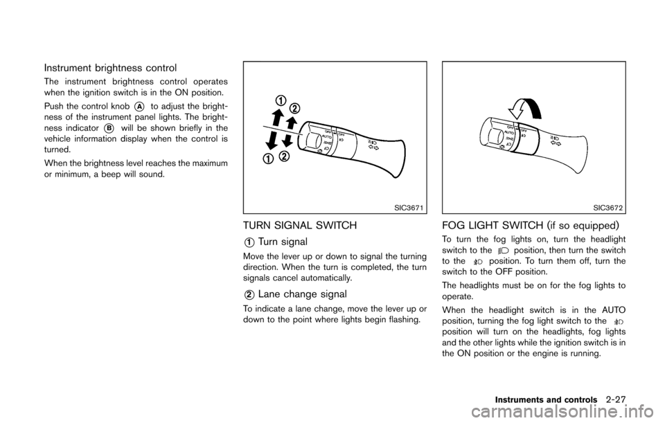
Instrument brightness control
The instrument brightness control operates
when the ignition switch is in the ON position.
Push the control knob
*Ato adjust the bright-
ness of the instrument panel lights. The bright-
ness indicator
*Bwill be shown briefly in the
vehicle information display when the control is
turned.
When the brightness level reaches the maximum
or minimum, a beep will sound.
SIC3671
TURN SIGNAL SWITCH
*1Turn signal
Move the lever up or down to signal the turning
direction. When the turn is completed, the turn
signals cancel automatically.
*2Lane change signal
To indicate a lane change, move the lever up or
down to the point where lights begin flashing.
SIC3672
FOG LIGHT SWITCH (if so equipped)
To turn the fog lights on, turn the headlight
switch to theposition, then turn the switch
to theposition. To turn them off, turn the
switch to the OFF position.
The headlights must be on for the fog lights to
operate.
When the headlight switch is in the AUTO
position, turning the fog light switch to the
position will turn on the headlights, fog lights
and the other lights while the ignition switch is in
the ON position or the engine is running.
Instruments and controls2-27
Page 135 of 332
3-22Pre-driving checks and adjustments
.Do not fill a portable fuel container
in the vehicle or trailer. Static elec-
tricity can cause an explosion of
flammable liquid, vapor or gas in
any vehicle or trailer. To reduce the
risk of serious injury or death when
filling portable fuel containers:
— Always place the container on
the ground when filling.
— Do not use electronic devices when filling.
— Keep the pump nozzle in contact with the container while you are
filling it.
— Use only approved portable fuel containers for flammable liquid.
CAUTION
. The LOOSE FUEL CAP warning
message will be displayed if the
fuel-filler cap is not properly tigh-
tened. It may take a few driving trips
for the message to be displayed.
Failure to tighten the fuel-filler cap
properly after the LOOSE FUEL CAP
warning message is displayed may cause the
Malfunction Indicator
Light (MIL) to illuminate.
. Failure to tighten the fuel-filler cap
properly may cause the
mal-
function indicator light (MIL) to
illuminate. If the
light illumi-
nates because the fuel-filler cap is
loose or missing, tighten or install
the cap and continue to drive the
vehicle. The
light should turn off
after a few driving trips. If the
light does not turn off after a few
driving trips, have the vehicle in-
spected by a NISSAN dealer.
For additional information, see
“Malfunction Indicator Light (MIL)”
(P.2-17) .
. If fuel is spilled on the vehicle body,
flush it away with water to avoid
paint damage.
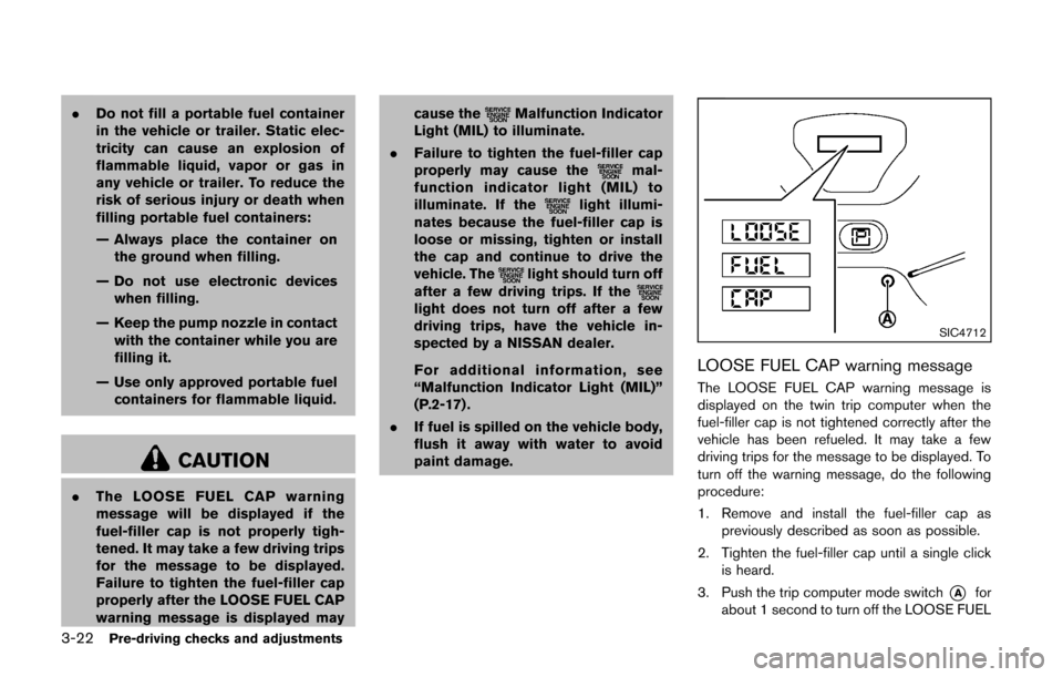
SIC4712
LOOSE FUEL CAP warning message
The LOOSE FUEL CAP warning message is
displayed on the twin trip computer when the
fuel-filler cap is not tightened correctly after the
vehicle has been refueled. It may take a few
driving trips for the message to be displayed. To
turn off the warning message, do the following
procedure:
1. Remove and install the fuel-filler cap as
previously described as soon as possible.
2. Tighten the fuel-filler cap until a single click is heard.
3. Push the trip computer mode switch
*Afor
about 1 second to turn off the LOOSE FUEL
Page 142 of 332
4 Center display, heater, air conditioner, audioand phone systems
Safety note ........................................................................\
.......... 4-2
Control panel buttons — color screen with navigation
system (if so equipped) .......................................................... 4-3
How to use touch screen ................................................. 4-3
How to use the BACK button ......................................... 4-5
How to use brightness control and display
ON/OFF button ................................................................... 4-5
How to use the setup button ........................................... 4-6
RearView monitor (if so equipped) ...................................... 4-9 How to read the displayed lines .................................. 4-10
Difference between predicted and
actual distances ................................................................ 4-10
How to adjust the screen .............................................. 4-13
Operating tips ................................................................... 4-13
Ventilators ........................................................................\
......... 4-13 Center ventilators ............................................................. 4-13
Side ventilators ................................................................. 4-14
Heater and air conditioner ................................................... 4-14 Manual air conditioner ..................................................... 4-15
Automatic air conditioner ............................................... 4-18 Operating tips (for automatic air conditioner) ........ 4-20
In-cabin microfilter ......................................................... 4-20
Servicing air conditioner .............................................. 4-20
Audio system ........................................................................\
.. 4-21 Audio operation precautions ....................................... 4-21
FM-AM radio with Compact Disc (CD) player ....... 4-32
FM-AM-SAT radio with Compact Disc
(CD) player ...................................................................... 4-39
CD/USB memory care and cleaning ........................ 4-47
Steering wheel switch for audio control .................. 4-47
Antenna ........................................................................\
.... 4-48
Car phone or CB radio ........................................................ 4-49
Bluetooth
®Hands-Free Phone System ........................... 4-50
Regulatory information .................................................. 4-51
Using the system ........................................................... 4-52
Control buttons ............................................................... 4-54
Getting started ............................................................... 4-54
List of voice commands ............................................... 4-56
Speaker Adaptation (SA) mode ................................. 4-59
Troubleshooting guide .................................................. 4-62
Page 143 of 332
4-2Center display, heater, air conditioner, audio and phone systems
WARNING
.Do not disassemble or modify this
system. If you do, it may result in
accidents, fire, or electric shock.
. Do not use this system if you notice
any abnormality, such as a frozen
screen or lack of sound. Continued
use of the system may result in
accident, fire or electric shock.
. In case you notice any foreign
object in the system hardware, spill
liquid on it, or notice smoke or smell
coming from it, stop using the
system immediately and contact
your nearest NISSAN dealer. Ignor-
ing such conditions may lead to
accidents, fire, or electric shock.
CAUTION
Do not use this system if you notice any
abnormality, such as a frozen screen or
lack of sound. Continued use of the
system may result in an accident, fire or
electric shock. Do not attempt to operate the system in
extreme temperature conditions [below
−
48F( −208 C) and above 1588 F (708C)].
Operating this system under these condi-
tions may result in system malfunctions.
SAFETY NOTE