Page 89 of 489

SUPPLEMENTAL AIR BAG
WARNING LIGHT
The supplemental air bag warning light,
displaying
in the instrument panel, moni-
tors the circuits for the air bag systems, preten-
sioners and all related wiring.
When the ignition switch is placed in the ON or
START position, the supplemental air bag warn-
ing light illuminates for about 7 seconds and then
turns off. This means the system is operational.
If any of the following conditions occur, the front
air bag, side air bag, curtain and rollover air bag
and pretensioner systems need servicing: ●
The supplemental air bag warning light re-
mains on after approximately 7 seconds.
● The supplemental air bag warning light
flashes intermittently.
● The supplemental air bag warning light does
not come on at all.
Under these conditions, the front air bag, side air
bag, curtain and rollover air bag or pretensioner
systems may not operate properly. They must be
checked and repaired. Take your vehicle to the
nearest NISSAN dealer.
WARNING
If the supplemental air bag warning light is
on, it could mean that the front air bag, side
air bag, curtain and rollover air bag and/or
pretensioner systems will not operate in an
accident. To help avoid injury to yourself or
others, have your vehicle checked by a
NISSAN dealer as soon as possible.
Repair and replacement procedure
The front air bags, side air bags, curtain and
rollover air bags and pretensioners are designed
to inflate on a one-time-only basis. As a reminder,
unless it is damaged, the supplemental air bag
warning light remains illuminated after inflation
has occurred. Repair and replacement of these
supplemental air bag systems should be done
only by a NISSAN dealer. When maintenance work is required on the ve-
hicle, the front air bags, side air bags, curtain and
rollover air bags, pretensioners and related parts
should be pointed out to the person performing
the maintenance. The ignition switch should al-
ways be in the LOCK position when working
under the hood or inside the vehicle.
WARNING
●
Once a front air bag, side air bag, or
curtain and rollover air bag has inflated,
the air bag module will not function
again and must be replaced. Addition-
ally, the activated pretensioners must
also be replaced. The air bag module
and pretensioner should be replaced by
a NISSAN dealer. The air bag module
and pretensioner cannot be repaired.
● The front air bag, side air bag, curtain
and rollover air bag systems and the
pretensioner system should be in-
spected by a NISSAN dealer if there is
any damage to the front end or side
portion of the vehicle.
● If you need to dispose of a supplemen-
tal air bag or pretensioner or scrap the
vehicle, contact a NISSAN dealer. Incor-
rect disposal procedures could cause
personal injury.
LRS0100
1-72Safety—Seats, seat belts and supplemental restraint system
Page 93 of 489
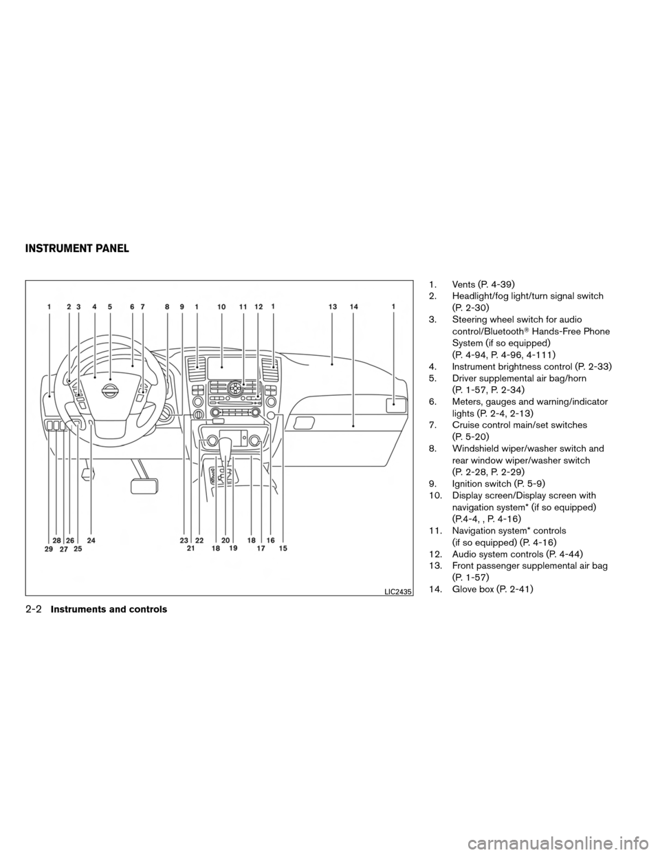
1. Vents (P. 4-39)
2. Headlight/fog light/turn signal switch(P. 2-30)
3. Steering wheel switch for audio
control/Bluetooth� Hands-Free Phone
System (if so equipped)
(P. 4-94, P. 4-96, 4-111)
4. Instrument brightness control (P. 2-33)
5. Driver supplemental air bag/horn
(P. 1-57, P. 2-34)
6. Meters, gauges and warning/indicator
lights (P. 2-4, 2-13)
7. Cruise control main/set switches
(P. 5-20)
8. Windshield wiper/washer switch and
rear window wiper/washer switch
(P. 2-28, P. 2-29)
9. Ignition switch (P. 5-9)
10. Display screen/Display screen with
navigation system* (if so equipped)
(P.4-4, , P. 4-16)
11. Navigation system* controls
(if so equipped) (P. 4-16)
12. Audio system controls (P. 4-44)
13. Front passenger supplemental air bag
(P. 1-57)
14. Glove box (P. 2-41)
LIC2435
INSTRUMENT PANEL
2-2Instruments and controls
Page 96 of 489
1. Speedometer
2. Odometer/twin trip display
3. Change button
SPEEDOMETER AND ODOMETER
Speedometer
The speedometer indicates vehicle speed.
Odometer/Twin trip odometer
The odometer/twin trip odometer is displayed
when the ignition switch is placed in the ON
position.
The odometer records the total distance the ve-
hicle has been driven.The twin trip odometer records the distance of
individual trips.
Changing the display:
Pushing the change button changes the display
as follows:
Trip
→
Trip→Odometer only
Elapsed time, driving distance and average
speed information is also available for vehicles
with navigation system (if so equipped) . Refer to
“Control panel buttons” in the “Display screen,
heater, air conditioner and audio systems” sec-
tion later in this manual.
Resetting the trip odometer:
Pushing the change button for more than 1 sec-
ond resets the currently displayed trip odometer
to zero.
WIC1502WIC1245
Instruments and controls2-5
Page 98 of 489
")
FUEL GAUGE
The gauge indicates theapproximatefuel level
in the tank.
The gauge may move slightly during braking,
turning, acceleration, or going up or down hills.
The gauge needle returns to E (Empty) after the
ignition key is turned to OFF.
The low fuel warning light comes on when the
amount of fuel in the tank is getting low.
Refill the fuel tank before the gauge regis-
ters E (Empty) . The
indicates that the fuel-filler door is
located on the driver’s side of the vehicle.
CAUTION
● If the vehicle runs out of fuel, theMalfunction Indicator Light (MIL) may
come on. Refuel as soon as possible.
After a few driving trips. the
light
should turn off. If the light remains on
after a few driving trips, have the ve-
hicle inspected by a NISSAN dealer.
● For additional information, see “Mal-
function Indicator Light (MIL)” later in
this section.
ENGINE OIL PRESSURE GAUGE
The gauge indicates the engine lubrication sys-
tem oil pressure while the engine is running. The
needle should be in the middle of the gauge when
the engine is running.
LIC1199LIC1198
Instruments and controls2-7
Page 99 of 489

● If the")
CAUTION
●This gauge is not designed to indicate
low engine oil level. Use the dipstick to
check the oil level. (See “Engine oil” in
the “Maintenance and do-it-yourself”
section.)
● If the gauge needle does not move with
the proper amount of engine oil, have
the vehicle checked by a NISSAN
dealer. Continued vehicle operation in
such a condition could cause serious
damage to the engine.
VOLTMETER
When the ignition switch is placed in the ON
position, the voltmeter indicates the battery volt-
age. When the engine is running, it indicates the
generator voltage.
While cranking the engine, the volts drop below
the normal range. If the needle is not in the normal
range (11 – 15 volts)
�1while the engine is
running, it may indicate that the charging system
is not functioning properly. Have the system
checked by a NISSAN dealer.
AUTOMATIC TRANSMISSION FLUID
TEMPERATURE GAUGE
This gauge indicates the temperature of the au-
tomatic transmission fluid. The automatic trans-
mission fluid temperature is in the normal range
�1when the gauge needle points within the zone
shown in the illustration.
LIC1136WIC1247
2-8Instruments and controls
Page 100 of 489

CAUTION
●This gauge is not designed to indicate
low automatic transmission fluid level.
Use the dipstick to check the fluid level.
(See “5-speed automatic transmission
fluid” in the “Maintenance and do-it-
yourself” section.)
● If the gauge indicates automatic trans-
mission fluid temperature over the nor-
mal range, stop the vehicle as soon as
safely possible. Have the vehicle
checked by a NISSAN dealer. Contin-
ued operation of the vehicle may seri-
ously damage the transmission. This unit measures terrestrial magnetism and in-
dicates the heading direction of the vehicle.
With the ignition switch in the ON position, press
the
orbutton as described in the
charts below to activate various features of the
automatic anti-glare rearview mirror.
Type A
Push and hold
the
button for about: Feature:
(Push button again for about 1 sec-
ond to change settings)
1 second Compass display toggles on/off
8 seconds Automatic anti-glare/indicator light
toggles on/off
11 seconds Compass zone can be changed to
correct false compass readings
13 seconds Compass enters calibration mode
Type B
Push and hold
the
button for about: Feature:
(Push button again for about 1 sec-
ond to change settings)
1 second Compass display toggles on/off
8 seconds Compass zone can be changed to
correct false compass readings
10 seconds Compass enters calibration mode
For information about the automatic anti-glare
feature, refer to “Automatic anti-glare rearview
mirror” in the “Pre-driving checks and adjust-
ments” section.
COMPASS DISPLAY (if so equipped)
Instruments and controls2-9
Page 101 of 489
COMPASS DISPLAY
Push theorbutton for about 1 sec-
ond when the ignition switch is placed in the ON
position to toggle the compass direction display
�1on or off. The display will indicate the direction
that the vehicle is heading.
N: North
E: East
S: South
W: West If the display reads “C”, calibrate the compass by
driving the vehicle in three complete circles at
less than 5 MPH (8 km/h).
You can also calibrate the compass by driving
your vehicle on your everyday route. The com-
pass will be calibrated once it has tracked three
complete circles.
Type A
WIC0904
Type B
LIC1487
2-10Instruments and controls
Page 104 of 489

warning light4WD warning light (model)High beam indicator light (Blue)
Automatic Transmission check warning lightLow fuel warning lightMalfunction indicator light (MIL")
orAnti-lock Braking System (ABS)
warning light4WD warning light (model)High beam indicator light (Blue)
Automatic Transmission check warning lightLow fuel warning lightMalfunction indicator light (MIL)
Automatic transmission park warning light
(model)Low tire pressure warning lightSecurity indicator light
orBrake warning lightMaster warning lightSlip indicator light
Charge warning lightSeat belt warning light and chimeTow mode ON indicator light (if so equipped)
Check suspension warning light (if so
equipped)Supplemental air bag warning lightTurn signal/hazard indicator lights
Engine oil pressure low/engine coolant tem-
perature high warning lightFront passenger air bag status lightVehicle Dynamic Control (VDC) OFF indicator
light
CHECKING BULBS
With all doors closed, apply the parking brake
and place the ignition switch in the ON position
without starting the engine. The following lights
will come on (if so equipped):
,or,,,,
The following lights come on briefly and then go
off (if so equipped):
or,,,,,
,
If any light fails to come on, it may indicate
a burned-out bulb or an open circuit in the
electrical system. Have the system repaired
promptly.
WARNING/INDICATOR LIGHTS AND
AUDIBLE REMINDERS
Instruments and controls2-13