2014 NISSAN 370Z ROADSTER display
[x] Cancel search: displayPage 296 of 428
SSD1021
PUSH-BUTTON IGNITION SWITCH
OPERATION
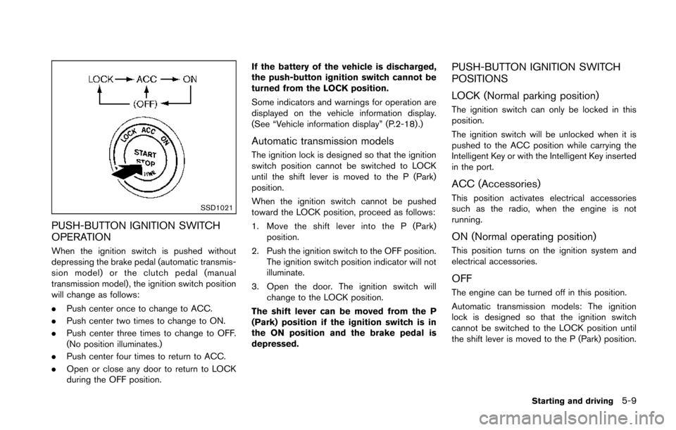
When the ignition switch is pushed without
depressing the brake pedal (automatic transmis-
sion model) or the clutch pedal (manual
transmission model) , the ignition switch position
will change as follows:
.Push center once to change to ACC.
. Push center two times to change to ON.
. Push center three times to change to OFF.
(No position illuminates.)
. Push center four times to return to ACC.
. Open or close any door to return to LOCK
during the OFF position. If the battery of the vehicle is discharged,
the push-button ignition switch cannot be
turned from the LOCK position.
Some indicators and warnings for operation are
displayed on the vehicle information display.
(See “Vehicle information display” (P.2-18) .)
Automatic transmission models
The ignition lock is designed so that the ignition
switch position cannot be switched to LOCK
until the shift lever is moved to the P (Park)
position.
When the ignition switch cannot be pushed
toward the LOCK position, proceed as follows:
1. Move the shift lever into the P (Park)
position.
2. Push the ignition switch to the OFF position. The ignition switch position indicator will not
illuminate.
3. Open the door. The ignition switch will change to the LOCK position.
The shift lever can be moved from the P
(Park) position if the ignition switch is in
the ON position and the brake pedal is
depressed.
PUSH-BUTTON IGNITION SWITCH
POSITIONS
LOCK (Normal parking position)
The ignition switch can only be locked in this
position.
The ignition switch will be unlocked when it is
pushed to the ACC position while carrying the
Intelligent Key or with the Intelligent Key inserted
in the port.
ACC (Accessories)
This position activates electrical accessories
such as the radio, when the engine is not
running.
ON (Normal operating position)
This position turns on the ignition system and
electrical accessories.
OFF
The engine can be turned off in this position.
Automatic transmission models: The ignition
lock is designed so that the ignition switch
cannot be switched to the LOCK position until
the shift lever is moved to the P (Park) position.
Starting and driving5-9
Page 297 of 428
5-10Starting and driving
EMERGENCY ENGINE SHUT OFF
To shut off the engine in an emergency situation
while driving perform the following procedure:
.Rapidly push the push-button ignition switch
3 consecutive times in less than 1.5
seconds, or
. Push and hold the push-button ignition
switch for more than 2 seconds.
CAUTION
Do not leave the vehicle with the push-
button ignition switch in ACC or ON
positions when the engine is not run-
ning for an extended period. This can
discharge the battery.SSD0826
INTELLIGENT KEY BATTERY DIS-
CHARGE
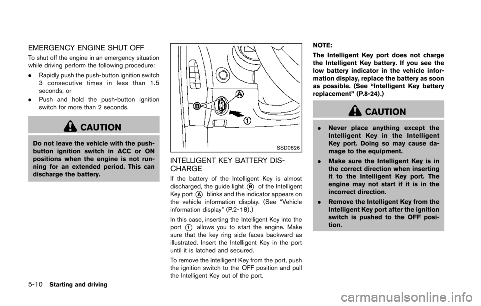
If the battery of the Intelligent Key is almost
discharged, the guide light
*Bof the Intelligent
Key port
*Ablinks and the indicator appears on
the vehicle information display. (See “Vehicle
information display” (P.2-18) .)
In this case, inserting the Intelligent Key into the
port
*1allows you to start the engine. Make
sure that the key ring side faces backward as
illustrated. Insert the Intelligent Key in the port
until it is latched and secured.
To remove the Intelligent Key from the port, push
the ignition switch to the OFF position and pull
the Intelligent Key out of the port. NOTE:
The Intelligent Key port does not charge
the Intelligent Key battery. If you see the
low battery indicator in the vehicle infor-
mation display, replace the battery as soon
as possible. (See “Intelligent Key battery
replacement” (P.8-24) .)
CAUTION
.
Never place anything except the
Intelligent Key in the Intelligent
Key port. Doing so may cause da-
mage to the equipment.
. Make sure the Intelligent Key is in
the correct direction when inserting
it to the Intelligent Key port. The
engine may not start if it is in the
incorrect direction.
. Remove the Intelligent Key from the
Intelligent Key port after the ignition
switch is pushed to the OFF posi-
tion.
Page 301 of 428
5-14Starting and driving
CAUTION
Use this position only when the vehicle
is completely stopped.
R (Reverse):
Use this position to back up. Always be sure the
vehicle is completely stopped before selecting
the R (Reverse) position. The brake pedal
must be depressed and the shift lever
button pushed in to move the shift lever
from the P (Park) position, the N (Neutral)
position or any drive position to the R
(Reverse) position.
N (Neutral):
Neither forward nor reverse gear is engaged.
The engine can be started in this position. You
may shift to the N (Neutral) position and restart a
stalled engine while the vehicle is moving.
D (Drive):
Use this position for all normal forward driving.
SSD0828Paddle shifter
Manual shift mode
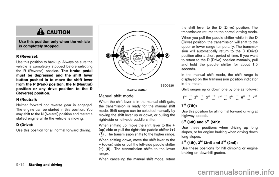
When the shift lever is in the manual shift gate,
the transmission is ready for the manual shift
mode. Shift ranges can be selected manually by
moving the shift lever up or down, or pulling the
right-side or left-side paddle shifter.
When shifting up, move the shift lever to the +
(up) side or pull the right-side paddle shifter (+)
*A. The transmission shifts to the higher range.
When shifting down, move the shift lever to the
− (down) side or pull the left-side paddle shifter
(−)
*B. The transmission shifts to the lower
range.
When canceling the manual shift mode, return the shift lever to the D (Drive) position. The
transmission returns to the normal driving mode.
When you pull the paddle shifter while in the D
(Drive) position, the transmission will shift to the
upper or lower range temporarily. The transmis-
sion will automatically return to the D (Drive)
position after a short period of time. If you want
to return to the D (Drive) position manually, pull
and hold the paddle shifter for about 1.5
seconds.
In the manual shift mode, the shift range is
displayed on the transmission position indicator
in the meter.
Shift ranges up or down one by one as follows:
1M?
/
2M?
/3M?
/ 4M?
/5M?
/6M?
/ 7M
7M(7th):
Use this position for all normal forward driving at
highway speeds.
6
M(6th) and 5M(5th):
Use these positions when driving up long
slopes, or for engine braking when driving down
long slopes.
4
M(4th) , 3M(3rd) and 2M(2nd):
Use these positions for hill climbing or engine
braking on downhill grades.
Page 302 of 428
1M(1st):
Use this position when climbing steep hills
slowly or driving slowly through deep snow, or
for maximum engine braking on steep downhill
grades.
. Remember not to drive at high speeds for
extended periods of time in lower than 7th
gear. This reduces fuel economy.
. Moving the shift lever rapidly to the same
side twice will shift the ranges in succes-
sion.
. In the manual shift mode, the transmis-
sion may not shift to the selected gear
or may automatically shift to the other
gear. This helps maintain driving per-
formance and reduces the chance of
vehicle damage or loss of control.
. When the transmission does not shift
to the selected gear, the Automatic
Transmission (AT) position indicator
light (on the instrument panel) will
blink and the buzzer will sound.
. In the manual shift mode, the transmis-
sion automatically shifts down to 1st
gear before the vehicle comes to a
stop. When accelerating again, it is
necessary to shift up to the desired
range.
SSD0832
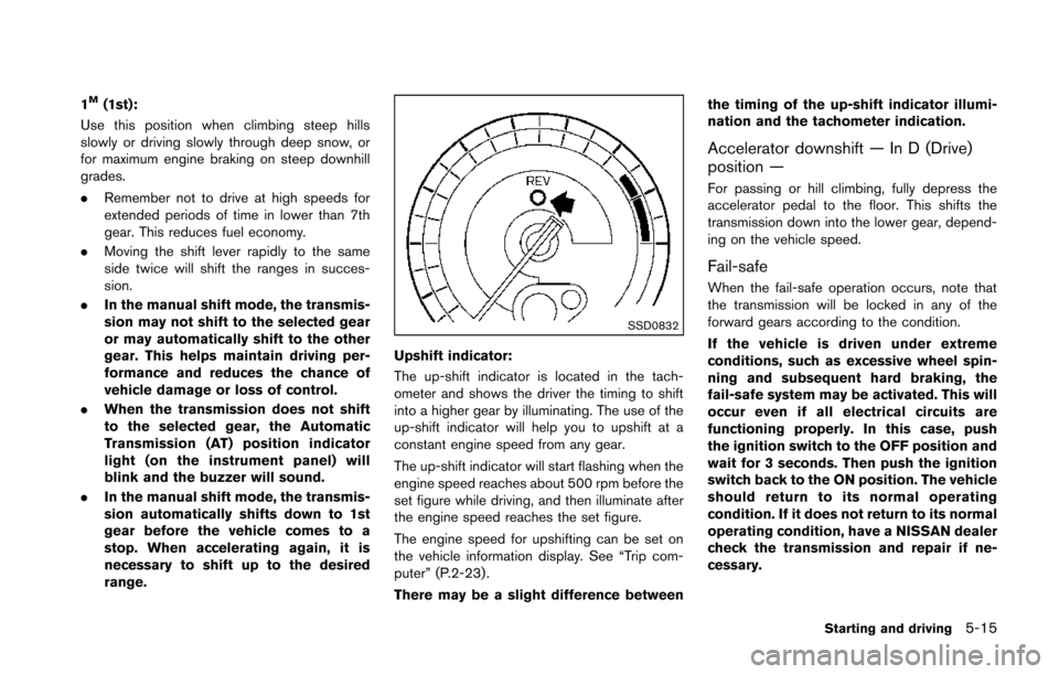
Upshift indicator:
The up-shift indicator is located in the tach-
ometer and shows the driver the timing to shift
into a higher gear by illuminating. The use of the
up-shift indicator will help you to upshift at a
constant engine speed from any gear.
The up-shift indicator will start flashing when the
engine speed reaches about 500 rpm before the
set figure while driving, and then illuminate after
the engine speed reaches the set figure.
The engine speed for upshifting can be set on
the vehicle information display. See “Trip com-
puter” (P.2-23) .
There may be a slight difference between the timing of the up-shift indicator illumi-
nation and the tachometer indication.
Accelerator downshift — In D (Drive)
position —
For passing or hill climbing, fully depress the
accelerator pedal to the floor. This shifts the
transmission down into the lower gear, depend-
ing on the vehicle speed.
Fail-safe
When the fail-safe operation occurs, note that
the transmission will be locked in any of the
forward gears according to the condition.
If the vehicle is driven under extreme
conditions, such as excessive wheel spin-
ning and subsequent hard braking, the
fail-safe system may be activated. This will
occur even if all electrical circuits are
functioning properly. In this case, push
the ignition switch to the OFF position and
wait for 3 seconds. Then push the ignition
switch back to the ON position. The vehicle
should return to its normal operating
condition. If it does not return to its normal
operating condition, have a NISSAN dealer
check the transmission and repair if ne-
cessary.
Starting and driving5-15
Page 305 of 428
5-18Starting and driving
SSD0830
SynchroRev Match mode (S-MODE) warn-
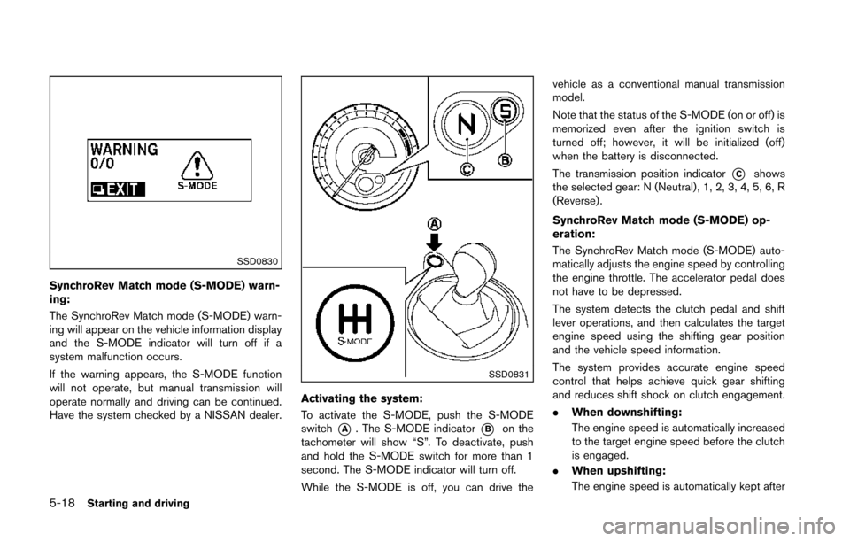
ing:
The SynchroRev Match mode (S-MODE) warn-
ing will appear on the vehicle information display
and the S-MODE indicator will turn off if a
system malfunction occurs.
If the warning appears, the S-MODE function
will not operate, but manual transmission will
operate normally and driving can be continued.
Have the system checked by a NISSAN dealer.
SSD0831
Activating the system:
To activate the S-MODE, push the S-MODE
switch
*A. The S-MODE indicator*Bon the
tachometer will show “S”. To deactivate, push
and hold the S-MODE switch for more than 1
second. The S-MODE indicator will turn off.
While the S-MODE is off, you can drive the vehicle as a conventional manual transmission
model.
Note that the status of the S-MODE (on or off) is
memorized even after the ignition switch is
turned off; however, it will be initialized (off)
when the battery is disconnected.
The transmission position indicator
*Cshows
the selected gear: N (Neutral) , 1, 2, 3, 4, 5, 6, R
(Reverse).
SynchroRev Match mode (S-MODE) op-
eration:
The SynchroRev Match mode (S-MODE) auto-
matically adjusts the engine speed by controlling
the engine throttle. The accelerator pedal does
not have to be depressed.
The system detects the clutch pedal and shift
lever operations, and then calculates the target
engine speed using the shifting gear position
and the vehicle speed information.
The system provides accurate engine speed
control that helps achieve quick gear shifting
and reduces shift shock on clutch engagement.
. When downshifting:
The engine speed is automatically increased
to the target engine speed before the clutch
is engaged.
. When upshifting:
The engine speed is automatically kept after
Page 306 of 428
the engine speed lowers to the target
engine speed.
Rapid clutch engagement before the engine
speed lowers to the target engine speed
may cause shift shock.
. When depressing the clutch pedal with
the gear engaged:
The engine speed is automatically kept at
the proper engine speed for the engaged
gear.
This function will not operate when low (1st)
gear is selected.
There is a delay between the clutch pedal
operation and the S-MODE operation. Make
sure the engine speed is adjusted before
engaging the clutch again.
SSD0832
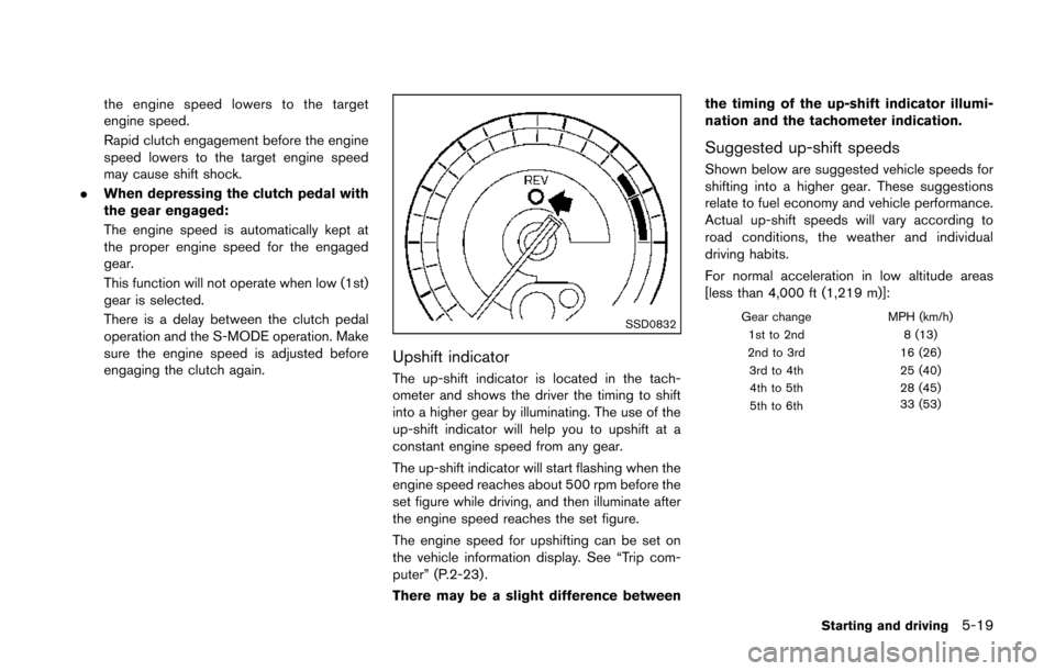
Upshift indicator
The up-shift indicator is located in the tach-
ometer and shows the driver the timing to shift
into a higher gear by illuminating. The use of the
up-shift indicator will help you to upshift at a
constant engine speed from any gear.
The up-shift indicator will start flashing when the
engine speed reaches about 500 rpm before the
set figure while driving, and then illuminate after
the engine speed reaches the set figure.
The engine speed for upshifting can be set on
the vehicle information display. See “Trip com-
puter” (P.2-23) .
There may be a slight difference between the timing of the up-shift indicator illumi-
nation and the tachometer indication.
Suggested up-shift speeds
Shown below are suggested vehicle speeds for
shifting into a higher gear. These suggestions
relate to fuel economy and vehicle performance.
Actual up-shift speeds will vary according to
road conditions, the weather and individual
driving habits.
For normal acceleration in low altitude areas
[less than 4,000 ft (1,219 m)]:
Gear change
MPH (km/h)
1st to 2nd 8 (13)
2nd to 3rd 16 (26)
3rd to 4th 25 (40)
4th to 5th 28 (45)
5th to 6th 33 (53)
Starting and driving5-19
Page 324 of 428
TIRE PRESSURE MONITORING SYS-
TEM (TPMS)
This vehicle is equipped with the Tire Pressure
Monitoring System (TPMS) . It monitors tire
pressure of all tires except the spare. When
the low tire pressure warning light is lit and the
CHECK TIRE PRESSURE warning appears on
the vehicle information display, one or more of
your tires is significantly under-inflated. If the
vehicle is being driven with low tire pressure, the
TPMS will activate and warn you of it by the low
tire pressure warning light. This system will
activate only when the vehicle is driven at
speeds above 16 MPH (25 km/h). For more
details, see “Warning/indicator lights and audi-
ble reminders” (P.2-10) and “Tire Pressure
Monitoring System (TPMS)” (P.5-3) .
WARNING
.If the low tire pressure warning light
illuminates while driving, avoid sud-
den steering maneuvers or abrupt
braking, reduce vehicle speed, pull
off the road to a safe location and
stop the vehicle as soon as possi-
ble. Driving with under-inflated tires
may permanently damage the tires
and increase the likelihood of tire failure. Serious vehicle damage
could occur and may lead to an
accident and could result in serious
personal injury. Check the tire pres-
sure for all four tires. Adjust the tire
pressure to the recommended COLD
tire pressure shown on the Tire and
Loading Information label to turn
the low tire pressure warning light
OFF. If the light still illuminates
while driving after adjusting the tire
pressure, a tire may be flat. If you
have a flat tire, replace it with a
spare tire as soon as possible.
. When a spare tire is mounted or a
wheel is replaced, the TPMS will not
function and the low tire pressure
warning light will flash for approxi-
mately 1 minute. The light will
remain on after 1 minute. Contact
your NISSAN dealer as soon as
possible for tire replacement and/
or system resetting.
. Replacing tires with those not ori-
ginally specified by NISSAN could
affect the proper operation of the
TPMS.
. Do not inject any tire liquid or
aerosol tire sealant into the tires, as this may cause a malfunction of
the tire pressure sensors (for mod-
els not equipped with the emer-
gency tire puncture repair kit) .
. If you used the Emergency Tire
Sealant to repair a minor tire punc-
ture, your NISSAN dealer will also
need to replace the TPMS sensor in
addition to repairing or replacing
the tire (for models equipped with
the emergency tire puncture repair
kit) .
. NISSAN recommends using only
NISSAN Genuine Emergency Tire
Sealant provided with your vehicle.
Other tire sealants may damage the
valve stem seal which can cause the
tire to lose air pressure (for models
equipped with the emergency tire
puncture repair kit) .
In case of emergency6-3
FLAT TIRE
Page 376 of 428
SDI2361
PASSENGER COMPARTMENT
CAUTION
Never use a fuse of a higher or lower
amperage rating than that specified on
the fuse box cover. This could damage
the electrical system or cause a fire.
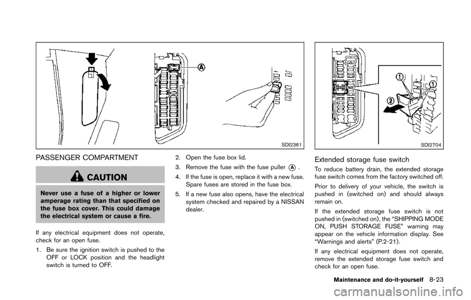
If any electrical equipment does not operate,
check for an open fuse.
1. Be sure the ignition switch is pushed to the OFF or LOCK position and the headlight
switch is turned to OFF. 2. Open the fuse box lid.
3. Remove the fuse with the fuse puller
*A.
4. If the fuse is open, replace it with a new fuse. Spare fuses are stored in the fuse box.
5. If a new fuse also opens, have the electrical system checked and repaired by a NISSAN
dealer.
SDI2704
Extended storage fuse switch
To reduce battery drain, the extended storage
fuse switch comes from the factory switched off.
Prior to delivery of your vehicle, the switch is
pushed in (switched on) and should always
remain on.
If the extended storage fuse switch is not
pushed in (switched on), the “SHIPPING MODE
ON, PUSH STORAGE FUSE” warning may
appear on the vehicle information display. See
“Warnings and alerts” (P.2-21) .
If any electrical equipment does not operate,
remove the extended storage fuse switch and
check for an open fuse.
Maintenance and do-it-yourself8-23