2014 NISSAN 370Z ROADSTER mirror
[x] Cancel search: mirrorPage 159 of 428
3-38Pre-driving checks and adjustments
light will turn off. Push the “I” switch*Dto turn
the system on.
Do not allow any object to cover the
sensors
*Eor apply glass cleaner on
them. Doing so will reduce the sensitivity
of the sensor, resulting in improper opera-
tion.
For the HomeLink
®Universal Transceiver opera-
tion, see “HomeLink®Universal Transceiver”
(P.2-50) .
OUTSIDE MIRRORS
WARNING
Objects viewed in the outside mirror on
the passenger side are closer than they
appear. Be careful when moving to the
right. Using only this mirror could cause
an accident. Use the inside mirror or
glance over your shoulder to properly
judge distances to other objects.
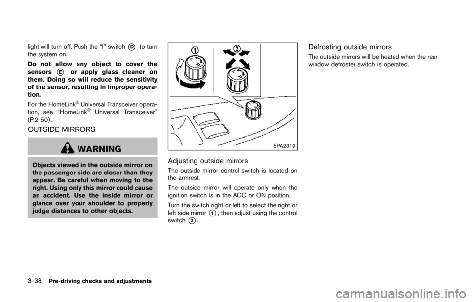
SPA2319
Adjusting outside mirrors
The outside mirror control switch is located on
the armrest.
The outside mirror will operate only when the
ignition switch is in the ACC or ON position.
Turn the switch right or left to select the right or
left side mirror
*1, then adjust using the control
switch
*2.
Defrosting outside mirrors
The outside mirrors will be heated when the rear
window defroster switch is operated.
Page 160 of 428
SPA1829
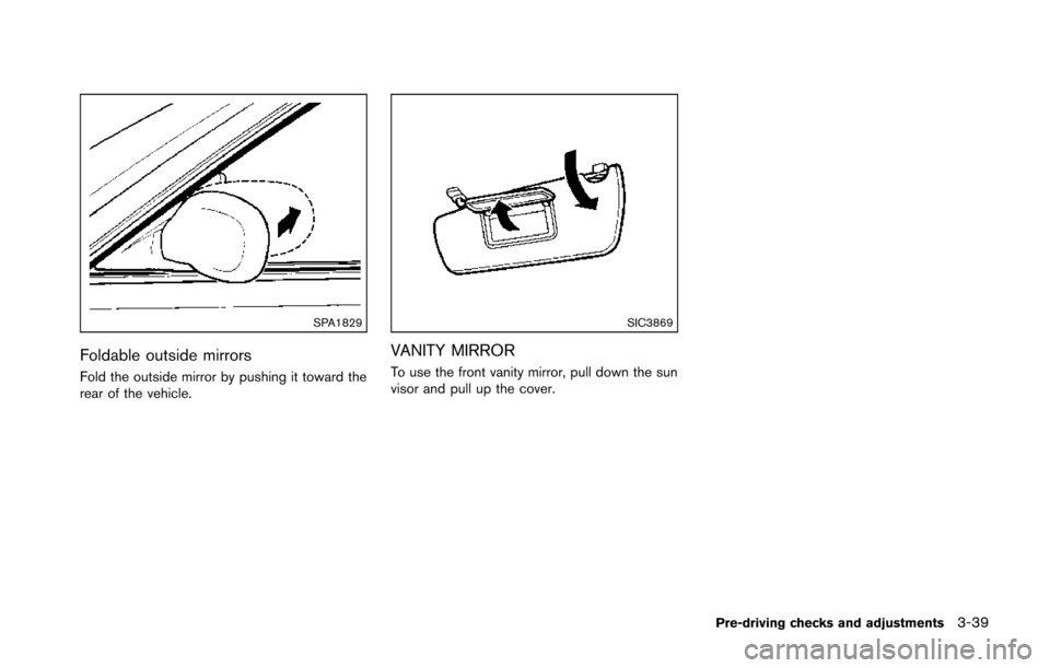
Foldable outside mirrors
Fold the outside mirror by pushing it toward the
rear of the vehicle.
SIC3869
VANITY MIRROR
To use the front vanity mirror, pull down the sun
visor and pull up the cover.
Pre-driving checks and adjustments3-39
Page 178 of 428
.(Previous)
Select the “
” key to display the previous
file.
Setting the Image Viewer:
The Image Viewer setting display will appear
when selecting the “Settings” key on the full
screen display. The following settings are
available for the full screen display.
. Slideshow Speed
Select the “Slideshow Speed” key. From the
following display, select the changing time
from 5, 10, 30, 60 seconds or “No Auto
Change”.
. Slideshow Order
Select the “Slideshow Order” key. From the
following display, select “Random” or “Order
List”. For “Order List”, the image order is the
order of the files as stored on the USB
memory.
Operating tips:
. Only files that meet the following conditions
will be displayed.
— Image type: JPEG
— File Extensions: *.jpg, *jpeg
— Maximum Resolution: 2048 61536
pixels — Maximum Size: 2-MB
— Colors: 32768 (15-bit)
— Maximum File Name lengths: 253-Bytes
— Maximum Folders: 500
— Maximum Images per Folder: 1024
. If an electronic device (such as a digital
camera) is directly connected to the vehicle
using a USB cable, no image will be
displayed on the screen.
. If the file name is too long, some file names
may not be entirely displayed.
. When the total number of characters in the
file name exceeds 100 or if 1 file name in a
directory exceeds 100 characters, all files
will show a shortened 8-character version.
The image will still be displayed when
selected. The system is designed as an aid to the driver in
situations such as slot parking or parallel
parking.
When the shift lever is shifted into the R
(Reverse) position, the monitor display shows
view to the rear of the vehicle.
WARNING
.
The RearView Monitor is a conve-
nience but it is not a substitute to
check behind the vehicle when
backing up.
. The driver is always responsible for
safety during parking and other
maneuvers.
. Objects viewed in the RearView
Monitor differ from actual distance
because a wide-angle lens is used.
Objects in the RearView Monitor
will appear visually opposite like
ones viewed in the inside and out-
side mirrors.
. Make sure that the trunk is securely
closed when backing up.
. Underneath the bumper and the
corner areas of the bumper cannot
be viewed on the RearView monitor
Center display, heater, air conditioner, audio, phone and voice recognition systems4-17
REARVIEW MONITOR (models with
navigation system)
Page 180 of 428
.The distance guide line and the
vehicle width guide line should be
used as a reference only when the
vehicle is on a level paved surface.
The distance viewed on the monitor
is for reference only and may be
different than the actual distance
between the vehicle and displayed
objects.
. When backing up the vehicle up a
hill, objects viewed in the monitor
are further than they appear. When
backing up the vehicle down a hill,
objects viewed in the monitor are
closer than they appear. Use the
inside mirror or glance over your
shoulder to properly judge dis-
tances to other objects.
The vehicle width and predictive course
lines are wider than the actual width and
course.
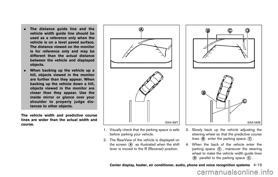
SAA1897
1. Visually check that the parking space is safe before parking your vehicle.
2. The RearView of the vehicle is displayed on the screen
*Aas illustrated when the shift
lever is moved to the R (Reverse) position.
SAA1898
3. Slowly back up the vehicle adjusting the steering wheel so that the predictive course
lines
*Benter the parking space*C.
4. When the back of the vehicle enter the parking space
*C, maneuver the steering
wheel to make the vehicle width guide lines
*Dparallel to the parking space*C.
Center display, heater, air conditioner, audio, phone and voice recognition systems4-19
Page 298 of 428
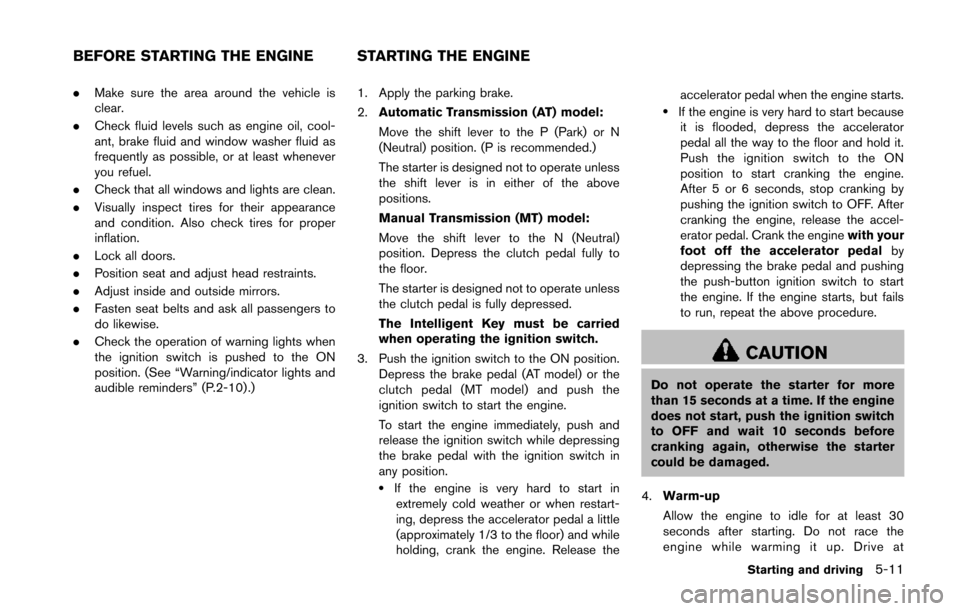
.Make sure the area around the vehicle is
clear.
. Check fluid levels such as engine oil, cool-
ant, brake fluid and window washer fluid as
frequently as possible, or at least whenever
you refuel.
. Check that all windows and lights are clean.
. Visually inspect tires for their appearance
and condition. Also check tires for proper
inflation.
. Lock all doors.
. Position seat and adjust head restraints.
. Adjust inside and outside mirrors.
. Fasten seat belts and ask all passengers to
do likewise.
. Check the operation of warning lights when
the ignition switch is pushed to the ON
position. (See “Warning/indicator lights and
audible reminders” (P.2-10) .) 1. Apply the parking brake.
2.
Automatic Transmission (AT) model:
Move the shift lever to the P (Park) or N
(Neutral) position. (P is recommended.)
The starter is designed not to operate unless
the shift lever is in either of the above
positions.
Manual Transmission (MT) model:
Move the shift lever to the N (Neutral)
position. Depress the clutch pedal fully to
the floor.
The starter is designed not to operate unless
the clutch pedal is fully depressed.
The Intelligent Key must be carried
when operating the ignition switch.
3. Push the ignition switch to the ON position. Depress the brake pedal (AT model) or the
clutch pedal (MT model) and push the
ignition switch to start the engine.
To start the engine immediately, push and
release the ignition switch while depressing
the brake pedal with the ignition switch in
any position.
.If the engine is very hard to start inextremely cold weather or when restart-
ing, depress the accelerator pedal a little
(approximately 1/3 to the floor) and while
holding, crank the engine. Release the accelerator pedal when the engine starts.
.If the engine is very hard to start because
it is flooded, depress the accelerator
pedal all the way to the floor and hold it.
Push the ignition switch to the ON
position to start cranking the engine.
After 5 or 6 seconds, stop cranking by
pushing the ignition switch to OFF. After
cranking the engine, release the accel-
erator pedal. Crank the engine with your
foot off the accelerator pedal by
depressing the brake pedal and pushing
the push-button ignition switch to start
the engine. If the engine starts, but fails
to run, repeat the above procedure.
CAUTION
Do not operate the starter for more
than 15 seconds at a time. If the engine
does not start, push the ignition switch
to OFF and wait 10 seconds before
cranking again, otherwise the starter
could be damaged.
4. Warm-up
Allow the engine to idle for at least 30
seconds after starting. Do not race the
engine while warming it up. Drive at
Starting and driving5-11
BEFORE STARTING THE ENGINE STARTING THE ENGINE
Page 381 of 428
8-28Maintenance and do-it-yourself
HEADLIGHTS
Fog may temporarily form inside the lens of the
exterior lights in the rain or in a car wash. A
temperature difference between the inside and
the outside of the lens causes the fog. This is
not a malfunction. If large drops of water collect
inside the lens, contact a NISSAN dealer.
Replacing
WARNING
HIGH VOLTAGE
When xenon headlights are on, they
produce a high voltage. To prevent an
electric shock, never attempt to modify
or disassemble. Always have your xe-
non headlights replaced at a NISSAN
dealer. For additional information, see
“Headlight and turn signal switch” (P.2-
33) .
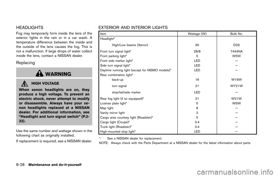
Use the same number and wattage shown in the
following chart as originally installed.
If replacement is required, see a NISSAN dealer.
EXTERIOR AND INTERIOR LIGHTS
Item Wattage (W)Bulb No.
Headlight*
High/Low beams (Xenon) 35D2S
Front turn signal light* 28/87444NA
Front parking light* 5W5W
Front side marker light* LED—
Side turn signal light* LED—
Daytime running light (except for NISMO models)* LED—
Rear combination light*
back-up 16W16W
turn signal 21WY21W
stop/tail/side marker LED—
Rear fog light (if so equipped)* 21W21W
License plate light* 5W5W
Map light 8—
Vanity mirror light 2—
Cargo area courtesy light (Roadster)* 5—
Cargo light (Coupe)* 3.4—
Trunk light (Roadster)* 3.4—
High-mounted stop light* LED—
*: See a NISSAN dealer for replacement.
NOTE: Always check with the Parts Department at a NISSAN dealer for the latest information about parts.
Page 382 of 428
Replacement procedures
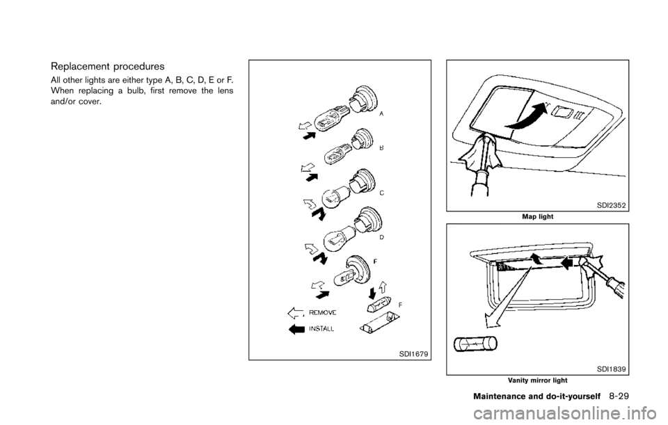
All other lights are either type A, B, C, D, E or F.
When replacing a bulb, first remove the lens
and/or cover.
SDI1679
SDI2352Map light
SDI1839Vanity mirror light
Maintenance and do-it-yourself8-29
Page 422 of 428
Fuel efficient driving tips ........................................... 5-23
Fuses.............................................................................. 8-22
Fusible links.................................................................. 8-22
G
Garage door opener, HomeLink®
Universal Transceiver.................................................. 2-50
Gas cap......................................................................... 3-34
Gauge .............................................................................. 2-5Engine coolant temperature gauge .................... 2-7
Fuel gauge................................................................ 2-8
Odometer.................................................................. 2-6
Speedometer............................................................ 2-6
Tachometer ............................................................... 2-7
Trip computer........................................................ 2-23
General maintenance .......................................... 8-3, 8-3
Glove box...................................................................... 2-42
H
Hands-free phone system, Bluetooth®
(models with navigation system)............................. 4-76
Hands-free phone system, Bluetooth®
(models without navigation system) ....................... 4-86
Hatch, Rear hatch....................................................... 3-17
Hazard warning flasher switch................................... 6-2
Head restraints .............................................................. 1-5
Headlights Bulb replacement................................................. 8-28
Headlight switch................................................... 2-33
Xenon headlights.................................................. 2-33
Heated seats................................................................ 2-37
Heater Engine block heater............................................. 5-33
Heater and air conditioner operation.............. 4-24
HomeLink
®Universal Transceiver ........................... 2-50 Hood release................................................................ 3-16
Horn................................................................................ 2-37
I
Ignition switch
(Push-button) ........................................................... 5-8
Manual transmission models............................. 5-16
Immobilizer system...................................................... 2-29
In-cabin microfilter ...................................................... 4-30
Indicator lights.............................................................. 2-15
INFO button.................................................................... 4-8
Inside mirror.................................................................. 3-37
Inspection/maintenance (I/M) test .......................... 9-24
Instrument brightness control .................................. 2-36
Instrument panel............................................................ 2-4
Instrument pocket ....................................................... 2-41
Intelligent Key................................................................. 3-2
Intelligent Key battery discharge indicator............ 2-20
Intelligent Key removal indicator.............................. 2-19
Intelligent Key system .................................................. 3-6 Battery replacement ............................................ 8-24
Intelligent Key system warning light................ 2-12
Key operating range ............................................... 3-8
Key operation ........................................................... 3-9
Warning signals.................................................... 3-11
Interior light control switch ....................................... 2-48
Interior light replacement........................................... 8-28
Interior lights................................................................. 2-47
Interior trunk lid release............................................. 3-20
iPod
®player operation............................................... 4-68
J
Jump starting................................................................ 6-14
K
Keyless entry (See remote keyless
entry system)................................................................ 3-13
Keys.................................................................................. 3-2 For Intelligent Key system..................................... 3-6
L
LabelsAir bag warning labels........................................ 1-40
Air conditioner specification label.................... 9-13
Emission control information label................... 9-12
Engine serial number........................................... 9-12
F.M.V.S.S./C.M.V.S.S. certification label ........ 9-12
Tire and Loading information label ....... 8-31, 9-13
Vehicle identification number (VIN) ................. 9-11
License plate, Installing front license plate .......... 9-14
Light Air bag warning light........................................... 1-40
Bulb replacement................................................. 8-26
Cargo area courtesy light .................................. 2-49
Cargo light............................................................. 2-49
Fog light switch.................................................... 2-36
Headlight switch................................................... 2-33
Headlights bulb replacement............................ 8-28
Indicator lights....................................................... 2-15
Interior light control switch ................................ 2-48
Interior lights.......................................................... 2-47
Map lights .............................................................. 2-47
Replacement.......................................................... 8-26
Trunk light............................................................... 2-50
Vanity mirror lights ............................................... 2-49
Warning/indicator lights and
audible reminders................................................. 2-11
Xenon headlights.................................................. 2-33
Lights, Exterior and interior light replacement ..... 8-28
10-3