2014 NISSAN 370Z COUPE sensor
[x] Cancel search: sensorPage 91 of 428
2-26Instruments and controls
SIC4037
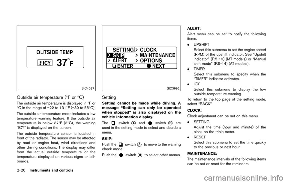
Outside air temperature (8For8C)
The outside air temperature is displayed in 8For
8C in the range of −22 to 1318F(−30 to 558C) .
The outside air temperature mode includes a low
temperature warning feature. If the outside air
temperature is below 378F(3 8C) , the warning
“ICY” is displayed on the screen.
The outside temperature sensor is located in
front of the radiator. The sensor may be affected
by road or engine heat, wind directions and
other driving conditions. The display may differ
from the actual outside temperature or the
temperature displayed on various signs or bill-
boards.
SIC3992
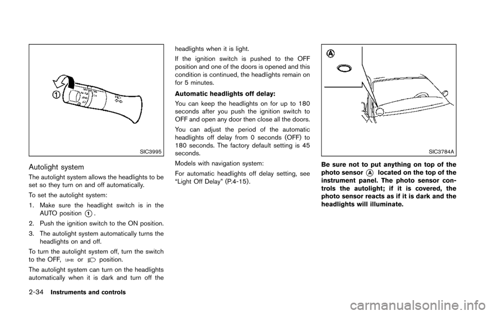
Setting
Setting cannot be made while driving. A
message “Setting can only be operated
when stopped” is also displayed on the
vehicle information display.
The
switch*Aandswitch*Bare
used in the setting mode to select and decide a
menu.
SKIP:
Push the
switch*Ato move to the warning
check mode.
Push the
switch*Bto select other menus. ALERT:
Alert menu can be set to notify the following
items.
.
UPSHIFT
Select this submenu to set the engine speed
(RPM) of the upshift indicator. See “Upshift
indicator” (P.5-19) (MT models) or “Manual
shift mode” (P.5-14) (AT models) .
. TIMER
Select this submenu to specify when the
“TIMER” indicator activates.
. ICY
Select this submenu to display the low
outside temperature warning.
To return to the top page of the setting mode,
select “BACK”.
CLOCK:
Clock adjustment can be set on this menu.
. SETTING
Adjust the time (hour and minute) of the
clock on the triple meter.
. RESET
Select this submenu to set the time quickly
to the previous or next hour.
MAINTENANCE:
The maintenance intervals of the following items
can be set or reset for the reminders.
Page 99 of 428
2-34Instruments and controls
SIC3995
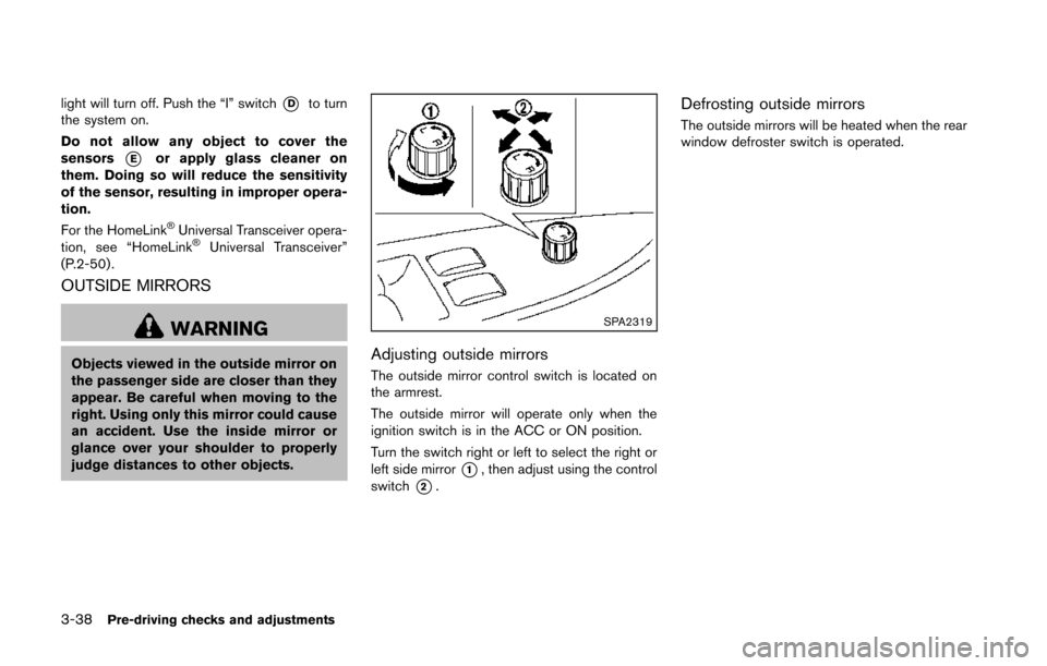
Autolight system
The autolight system allows the headlights to be
set so they turn on and off automatically.
To set the autolight system:
1. Make sure the headlight switch is in theAUTO position
*1.
2. Push the ignition switch to the ON position.
3. The autolight system automatically turns the headlights on and off.
To turn the autolight system off, turn the switch
to the OFF,
orposition.
The autolight system can turn on the headlights
automatically when it is dark and turn off the headlights when it is light.
If the ignition switch is pushed to the OFF
position and one of the doors is opened and this
condition is continued, the headlights remain on
for 5 minutes.
Automatic headlights off delay:
You can keep the headlights on for up to 180
seconds after you push the ignition switch to
OFF and open any door then close all the doors.
You can adjust the period of the automatic
headlights off delay from 0 seconds (OFF) to
180 seconds. The factory default setting is 45
seconds.
Models with navigation system:
For automatic headlights off delay setting, see
“Light Off Delay” (P.4-15) .
SIC3784A
Be sure not to put anything on top of the
photo sensor
*Alocated on the top of the
instrument panel. The photo sensor con-
trols the autolight; if it is covered, the
photo sensor reacts as if it is dark and the
headlights will illuminate.
Page 159 of 428
3-38Pre-driving checks and adjustments
light will turn off. Push the “I” switch*Dto turn
the system on.
Do not allow any object to cover the
sensors
*Eor apply glass cleaner on
them. Doing so will reduce the sensitivity
of the sensor, resulting in improper opera-
tion.
For the HomeLink
®Universal Transceiver opera-
tion, see “HomeLink®Universal Transceiver”
(P.2-50) .
OUTSIDE MIRRORS
WARNING
Objects viewed in the outside mirror on
the passenger side are closer than they
appear. Be careful when moving to the
right. Using only this mirror could cause
an accident. Use the inside mirror or
glance over your shoulder to properly
judge distances to other objects.
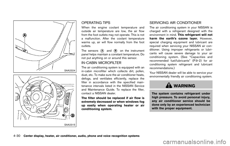
SPA2319
Adjusting outside mirrors
The outside mirror control switch is located on
the armrest.
The outside mirror will operate only when the
ignition switch is in the ACC or ON position.
Turn the switch right or left to select the right or
left side mirror
*1, then adjust using the control
switch
*2.
Defrosting outside mirrors
The outside mirrors will be heated when the rear
window defroster switch is operated.
Page 191 of 428
4-30Center display, heater, air conditioner, audio, phone and voice recognition systems
SAA2324
SAA2315
OPERATING TIPS
When the engine coolant temperature and
outside air temperature are low, the air flow
from the foot outlets may not operate. This is not
a malfunction. After the coolant temperature
warms up, air will flow normally from the foot
outlets.
The sensors
*Aand*Bon the instrument
panel helps maintain a constant temperature. Do
not put anything on or around this sensor.
IN-CABIN MICROFILTER
The air conditioning system is equipped with an
in-cabin microfilter which collects dirt, pollen,
dust, etc. To make sure the air conditioner heats,
defogs, and ventilates efficiently, replace the
filter in accordance with the specified main-
tenance intervals listed in the NISSAN Service
and Maintenance Guide. To replace the filter,
contact a NISSAN dealer.
The filter should be replaced if air flow is
extremely decreased or when windows fog
up easily when operating heater or air
conditioning system.
SERVICING AIR CONDITIONER
The air conditioning system in your NISSAN is
charged with a refrigerant designed with the
environment in mind. This refrigerant will not
harm the earth’s ozone layer. However,
special charging equipment and lubricant are
required when servicing your NISSAN air con-
ditioner. Using improper refrigerants or lubri-
cants will cause severe damage to your air
conditioning system. (See “Capacities and
recommended fuel/lubricants” (P.9-2) for air
conditioning system refrigerant and lubricant
recommendations.)
Your NISSAN dealer will be able to service your
environmentally friendly air conditioning system.
WARNING
The system contains refrigerant under
high pressure. To avoid personal injury,
any air conditioner service should be
done only by an experienced technician
with the proper equipment.
Page 292 of 428
the low tire pressure warning light
OFF. If the light still illuminates
while driving after adjusting the tire
pressure, a tire may be flat. If you
have a flat tire, replace it with a
spare tire as soon as possible. (See
“Flat tire” (P.6-3) for changing a flat
tire.)
. When a spare tire is mounted or a
wheel is replaced, the TPMS will not
function and the low tire pressure
warning light will flash for approxi-
mately 1 minute. The light will
remain on after 1 minute. Contact
your NISSAN dealer as soon as
possible for tire replacement and/
or system resetting.
. Replacing tires with those not ori-
ginally specified by NISSAN could
affect the proper operation of the
TPMS.
. Do not inject any tire liquid or
aerosol tire sealant into the tires,
as this may cause a malfunction of
the tire pressure sensors (for mod-
els not equipped with the emer-
gency tire puncture repair kit) .
. If you used the Emergency Tire
Sealant to repair a minor tire punc- ture, your NISSAN dealer will also
need to replace the TPMS sensor in
addition to repairing or replacing
the tire (for models equipped with
the emergency tire puncture repair
kit) .
. NISSAN recommends using only
NISSAN Genuine Emergency Tire
Sealant provided with your vehicle.
Other tire sealants may damage the
valve stem seal which can cause the
tire to lose air pressure (for models
equipped with the emergency tire
puncture repair kit) .
CAUTION
.The TPMS may not function properly
when the wheels are equipped with
tire chains or the wheels are buried
in snow.
. Do not place metalized film or any
metal parts (antenna, etc.) on the
windows. This may cause poor re-
ception of the signals from the tire
pressure sensors, and the TPMS will
not function properly. Some devices and transmitters may temporarily
interfere with the operation of the TPMS and
cause the low tire pressure warning light to
illuminate. Some examples are:
.
Facilities or electric devices using similar
radio frequencies are near the vehicle.
. If a transmitter set to similar frequencies is
being used in or near the vehicle.
. If a computer (or similar equipment) or a DC/
AC converter is being used in or near the
vehicle.
FCC Notice:
For USA:
This device complies with Part 15 of the
FCC Rules. Operation is subject to the
following two conditions: (1) This device
may not cause harmful interference, and
(2) this device must accept any interfer-
ence received, including interference that
may cause undesired operation.
NOTE:
Changes or modifications not expressly
approved by the party responsible for
compliance could void the user’s authority
to operate the equipment.
Starting and driving5-5
Page 315 of 428
5-28Starting and driving
surfaces even with ABS. Stopping
distances may also be longer on
rough, gravel or snow covered
roads, or if you are using tire chains.
Always maintain a safe distance
from the vehicle in front of you.
Ultimately, the driver is responsible
for safety.
. Tire type and condition may also
affect braking effectiveness.
— When replacing tires, install the
specified size of tires on all four
wheels.
— When installing a spare tire, make sure that it is the proper
size and type as specified on the
Tire and Loading Information
label. See “Tire and Loading
Information label” (P.9-13) of
this manual.
— For detailed information, see “Wheels and tires” (P.8-30) of
this manual.
The Anti-lock Braking System (ABS) controls
the brakes so the wheels do not lock during hard
braking or when braking on slippery surfaces.
The system detects the rotation speed at each wheel and varies the brake fluid pressure to
prevent each wheel from locking and sliding. By
preventing each wheel from locking, the system
helps the driver maintain steering control and
helps to minimize swerving and spinning on
slippery surfaces.
Using the system
Depress the brake pedal and hold it down.
Depress the brake pedal with firm steady
pressure, but do not pump the brakes. The
ABS will operate to prevent the wheels from
locking up. Steer the vehicle to avoid obstacles.
WARNING
Do not pump the brake pedal. Doing so
may result in increased stopping dis-
tances.
Self-test feature
The ABS includes electronic sensors, electric
pumps, hydraulic solenoids and a computer. The
computer has a built-in diagnostic feature that
tests the system each time you start the engine
and move the vehicle at a low speed in forward
or reverse. When the self-test occurs, you may
hear a “clunk” noise and/or feel a pulsation in the
brake pedal. This is normal and does notindicate a malfunction. If the computer senses
a malfunction, it switches the ABS off and
illuminates the ABS warning light on the
instrument panel. The brake system then oper-
ates normally, but without anti-lock assistance.
If the ABS warning light illuminates during the
self-test or while driving, have the vehicle
checked by a NISSAN dealer.
Normal operation
The ABS operates at speeds above 3 to 6 MPH
(5 to 10 km/h).
When the ABS senses that one or more wheels
are close to locking up, the actuator rapidly
applies and releases hydraulic pressure. This
action is similar to pumping the brakes very
quickly. You may feel a pulsation in the brake
pedal and hear a noise from under the hood or
feel a vibration from the actuator when it is
operating. This is normal and indicates that the
ABS is operating properly. However, the pulsa-
tion may indicate that road conditions are
hazardous and extra care is required while
driving.
Page 316 of 428
The Vehicle Dynamic Control (VDC) system
uses various sensors to monitor driver inputs
and vehicle motion. Under certain driving con-
ditions, the VDC system helps to perform the
following functions.
.Controls brake pressure to reduce wheel
slip on one slipping drive wheel so power is
transferred to a non slipping drive wheel on
the same axle.
. Controls brake pressure and engine output
to reduce drive wheel slip based on vehicle
speed (traction control function) .
. Controls brake pressure at individual wheels
and engine output to help the driver maintain
control of the vehicle in the following
conditions:
— understeer (vehicle tends to not follow
the steered path despite increased
steering input)
— oversteer (vehicle tends to spin due to certain road or driving conditions) .
The VDC system can help the driver to maintain
control of the vehicle, but it cannot prevent loss
of vehicle control in all driving situations.
When the VDC system operates, the VDC
warning light
in the instrument panel flashes
so note the following:
. The road may be slippery or the system may
determine some action is required to help keep the vehicle on the steered path.
. You may feel a pulsation in the brake pedal
and hear a noise or vibration from under the
hood. This is normal and indicates that the
VDC system is working properly.
. Adjust your speed and driving to the road
conditions.
See “Vehicle Dynamic Control (VDC) warning
light” (P.2-15).
If a malfunction occurs in the system, the VDC
warning light
illuminates in the instrument
panel. The VDC system automatically turns off.
The VDC OFF switch is used to turn off the VDC
system. The VDC off indicator
illuminates to
indicate the VDC system is off. When the VDC
switch is used to turn off the system, the VDC
system still operates to prevent one drive wheel
from slipping by transferring power to a non
slipping drive wheel. The VDC warning light
flashes if this occurs. All other VDC functions
are off, and the VDC warning lightwill not
flash. The VDC system is automatically reset to
on when the ignition switch is placed in the off
position then back to the on position.
See “Vehicle Dynamic Control (VDC) warning
light” (P.2-15) and “Vehicle Dynamic Control
(VDC) off indicator light” (P.2-17).
The computer has a built-in diagnostic feature
that tests the system each time you start the engine and move the vehicle forward or in
reverse at a slow speed. When the self-test
occurs, you may hear a “clunk” noise and/or feel
a pulsation in the brake pedal. This is normal and
is not an indication of a malfunction.
WARNING
.
The VDC system is designed to help
the driver maintain stability but
does not prevent accidents due to
abrupt steering operation at high
speeds or by careless or dangerous
driving techniques. Reduce vehicle
speed and be especially careful
when driving and cornering on slip-
pery surfaces and always drive care-
fully.
. Do not modify the vehicle’s suspen-
sion. If suspension parts such as
shock absorbers, struts, springs,
stabilizer bars, bushings and
wheels are not NISSAN recom-
mended for your vehicle or are
extremely deteriorated, the VDC
system may not operate properly.
This could adversely affect vehicle
handling performance, and the VDC
warning light
may illuminate.
Starting and driving5-29
VEHICLE DYNAMIC CONTROL (VDC)
SYSTEM
Page 324 of 428
TIRE PRESSURE MONITORING SYS-
TEM (TPMS)
This vehicle is equipped with the Tire Pressure
Monitoring System (TPMS) . It monitors tire
pressure of all tires except the spare. When
the low tire pressure warning light is lit and the
CHECK TIRE PRESSURE warning appears on
the vehicle information display, one or more of
your tires is significantly under-inflated. If the
vehicle is being driven with low tire pressure, the
TPMS will activate and warn you of it by the low
tire pressure warning light. This system will
activate only when the vehicle is driven at
speeds above 16 MPH (25 km/h). For more
details, see “Warning/indicator lights and audi-
ble reminders” (P.2-10) and “Tire Pressure
Monitoring System (TPMS)” (P.5-3) .
WARNING
.If the low tire pressure warning light
illuminates while driving, avoid sud-
den steering maneuvers or abrupt
braking, reduce vehicle speed, pull
off the road to a safe location and
stop the vehicle as soon as possi-
ble. Driving with under-inflated tires
may permanently damage the tires
and increase the likelihood of tire failure. Serious vehicle damage
could occur and may lead to an
accident and could result in serious
personal injury. Check the tire pres-
sure for all four tires. Adjust the tire
pressure to the recommended COLD
tire pressure shown on the Tire and
Loading Information label to turn
the low tire pressure warning light
OFF. If the light still illuminates
while driving after adjusting the tire
pressure, a tire may be flat. If you
have a flat tire, replace it with a
spare tire as soon as possible.
. When a spare tire is mounted or a
wheel is replaced, the TPMS will not
function and the low tire pressure
warning light will flash for approxi-
mately 1 minute. The light will
remain on after 1 minute. Contact
your NISSAN dealer as soon as
possible for tire replacement and/
or system resetting.
. Replacing tires with those not ori-
ginally specified by NISSAN could
affect the proper operation of the
TPMS.
. Do not inject any tire liquid or
aerosol tire sealant into the tires, as this may cause a malfunction of
the tire pressure sensors (for mod-
els not equipped with the emer-
gency tire puncture repair kit) .
. If you used the Emergency Tire
Sealant to repair a minor tire punc-
ture, your NISSAN dealer will also
need to replace the TPMS sensor in
addition to repairing or replacing
the tire (for models equipped with
the emergency tire puncture repair
kit) .
. NISSAN recommends using only
NISSAN Genuine Emergency Tire
Sealant provided with your vehicle.
Other tire sealants may damage the
valve stem seal which can cause the
tire to lose air pressure (for models
equipped with the emergency tire
puncture repair kit) .
In case of emergency6-3
FLAT TIRE