2014 MINI Paceman ESP
[x] Cancel search: ESPPage 51 of 282

Rear1.Pull upward as far as possible.2.Fold the backrest forward slightly.3.Press button 1 and pull out the head re‐
straint all the way to the stop.4.Press the additional button 2 using a suita‐
ble tool.5.Pull out the head restraint completely.6.Fold back the rear seat backrest.
Mirrors
Exterior mirrors
General information
The mirror on the passenger side is more
curved than the driver's mirror.
Estimating distances correctly
Objects reflected in the mirror are closer
than they appear. Do not estimate the distance to the traffic behind you based on what you see
in the mirror, as this will increase your risk of an
accident. ◀
At a glance
1Adjusting2Selecting the left/right mirror3Folding the mirror in and outSelecting a mirror To change to the other mirror: slide the
mirror switch over.
Adjusting electrically The setting corresponds to the direction
in which the button is pressed.
Adjusting manually If an electrical malfunction occurs, for example,
press the edges of the mirror glass.
Folding the mirror in and out
Press button 3.
The mirror can be folded in up to a vehicle
speed of approx. 20 mph/30 km/h.
For example, this is advantageous▷In car washes.▷In narrow streets.▷For folding back mirrors that were folded
away manually.
Fold in the mirror in a car wash
Before entering an automatic car wash,
fold in the exterior mirrors by hand or with the
button; otherwise, they could be damaged, de‐
pending on the width of the vehicle. ◀
Automatic heating Both exterior mirrors are heated automatically
while the engine is running or the ignition is
switched on when the external temperature is
below a certain value.
Seite 51AdjustingControls51
Online Edition for Part no. 01 40 2 911 544 - VI/13
Page 53 of 282

Transporting children safelyVehicle equipment
This chapter describes all series equipment as
well as country-specific and special equipment
offered for this model series.Therefore, it also
describes equipment that may not be found in
your vehicle, for instance due to the selected
special equipment or the country version. This
also applies to safety-related functions and sys‐
tems.
The right place for chil‐
dren
Notes Children in the vehicle
Do not leave children unattended in the
vehicle; otherwise, they could endanger them‐
selves and other persons, e.g., by opening the
doors. ◀
Children should always be in the rear Accident research shows that the safest place
for children is on the rear seat.
Transporting children in the rear
Transport children younger than 13 years
of age or shorter than 5 ft/150 cm in the rear
only, using child restraint fixing systems suita‐
ble for the age, weight, and height of the child; otherwise, there is an increased risk of injury in
an accident.
Children 13 years of age or older must wear a
safety belt as soon as a suitable child restraint fixing system can no longer be used, due to
their age, weight and size. ◀Installing child seats
Only install child seats in the rear when
the rear seat backrest is folded all the way back
and engaged; otherwise, there is an increased
risk of injury in an accident. ◀
Children on the front passenger seat
Front passenger airbags Should it be necessary to use a child restraint
fixing system on the front passenger seat,
make sure that the front and side airbags on
the front passenger side are deactivated, refer
to page 83.
Deactivating the front passenger airbags
If a child restraint fixing system is used in
the front passenger seat, the front passenger
airbags must be deactivated; otherwise, there
is an increased risk of injury to the child when
the airbags are triggered, even with a child re‐
straint fixing system. ◀
Installing child re‐
straint fixing systems
Before mounting MINI Countryman: before mounting a child re‐
straint fixing system on the rear seats, move
the seats into the rearmost positions.
Adjust the inclination of the center backrest to
that of the respective outer backrest.
After mounting the child restraint fixing system
on the respective outer rear seat, adjust the
backrest forward, if necessary, to ensure that
the backrest is in contact with the child re‐
straint fixing system. Rear seat backrests, refer
to page 110.Seite 53Transporting children safelyControls53
Online Edition for Part no. 01 40 2 911 544 - VI/13
Page 68 of 282

DisplaysVehicle equipment
This chapter describes all series equipment as
well as country-specific and special equipment
offered for this model series.Therefore, it also
describes equipment that may not be found in
your vehicle, for instance due to the selected
special equipment or the country version. This
also applies to safety-related functions and sys‐
tems.
Odometer, external tem‐
perature display, clock
At a glance1Current speed2Odometer, trip odometer, external temper‐
ature, time3Resetting the trip odometer
Press the button on the turn indicator lever to
open information in display area 2.
The following information is displayed consecu‐
tively:
▷Trip odometer▷Time▷External temperatureTrip odometer
To display the trip odometer: briefly press
knob 3.
To reset the trip odometer: press knob 3 while
the trip odometer is being displayed and the ig‐
nition is switched on.
Time Set the time, refer to page 72.
External temperature, external temperature warning
If the display drops to +37 ℉/+3 ℃, a signal
sounds and a warning lamp lights up. There is
the increased danger of ice.
Ice on roads
Even at temperatures above
+37 ℉/+3 ℃, there can be a risk of ice on
roads.
Therefore, drive carefully on bridges and shady
roads, for example, to avoid the increased dan‐
ger of an accident. ◀
Units of measure
To set the respective units of measure, miles or
km for the odometer and ℃ or ℉ for the exter‐
nal temperature, refer to page 72.Seite 68ControlsDisplays68
Online Edition for Part no. 01 40 2 911 544 - VI/13
Page 70 of 282

To set the corresponding units of measure, re‐
fer to page 72.
Information in detail
Range
Displays the estimated cruising range available
with the remaining fuel.
It is calculated based on your driving style over
the last 18 miles/30 km.
Average fuel consumption
This is calculated for the period during which
the engine is running.
With the trip computer, refer to page 70, the
average consumption can be displayed for an
additional distance.
To reset the average consumption: press the
button on the turn indicator lever for ap‐
prox. 2 seconds.
Current fuel consumption Displays the current fuel consumption. You can
check whether you are currently driving in an
efficient and environmentally-friendly manner.
Average speed Periods in which the vehicle was parked and
the engine was switched off manually are not
included in the average speed calculations.
With the trip computer, refer to page 70, the
average speed can be displayed for an addi‐
tional distance.
To reset the average speed: press the button
on the turn indicator lever for approx. 2 sec‐
onds.
Displays on the Control Display Display the computer or trip computer on the
Control Display.1."Vehicle Info"2."Onboard info" or "Trip computer"
Displays on the "Onboard info":
▷Range.▷Distance to destination.▷Estimated time of arrival if a destination
was entered in the navigation system.
Displays on the "Trip computer":
▷Departure time.▷Trip duration.▷Trip distance.
Both displays show:
▷Average fuel consumption.▷Average speed.Seite 70ControlsDisplays70
Online Edition for Part no. 01 40 2 911 544 - VI/13
Page 71 of 282

Resetting the fuel consumption and
speed
Resetting the values for average speed and
average fuel consumption:1.Select the respective menu item and press
the MINI joystick.2.Press the MINI joystick again to confirm
your selection.
Resetting the trip computer
Resetting all values:
1."Vehicle Info"2."Trip computer"3."Reset"
Settings and information
Operating concept
Some settings and information can only be cre‐
ated or opened while the ignition is switched
on, the vehicle is standing, and the doors are
closed.
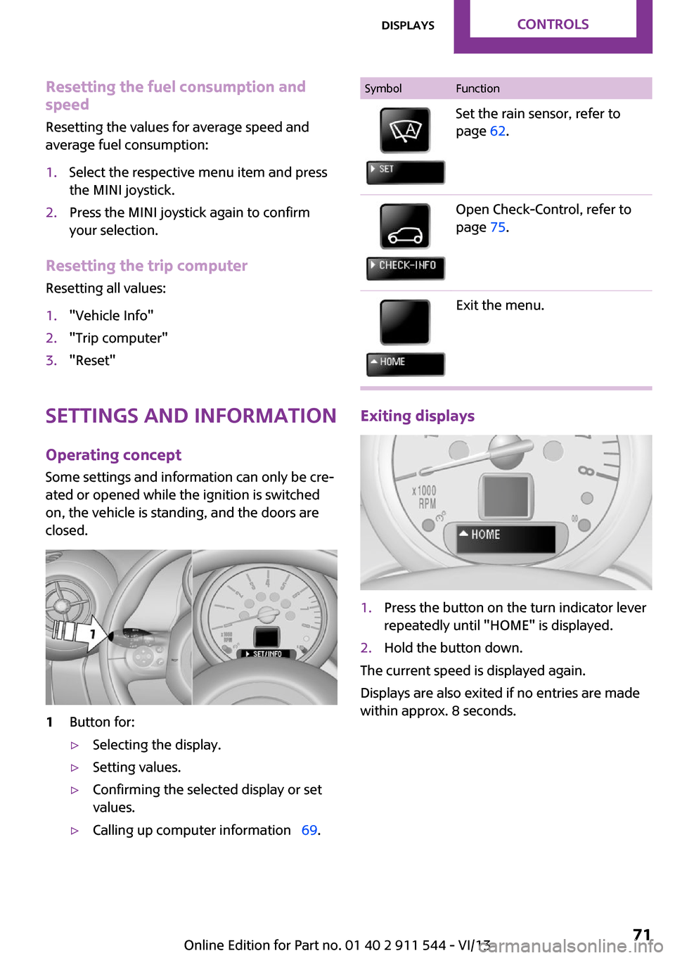
1Button for:▷Selecting the display.▷Setting values.▷Confirming the selected display or set
values.▷Calling up computer information 69.SymbolFunctionSet the rain sensor, refer to
page 62.Open Check-Control, refer to
page 75.Exit the menu.
Exiting displays
1.Press the button on the turn indicator lever
repeatedly until "HOME" is displayed.2.Hold the button down.
The current speed is displayed again.
Displays are also exited if no entries are made
within approx. 8 seconds.
Seite 71DisplaysControls71
Online Edition for Part no. 01 40 2 911 544 - VI/13
Page 76 of 282

Text messages
Text messages at the upper edge of the Control
Display in combination with a symbol in the in‐
strument cluster explain a Check Control mes‐
sage and the meaning of the indicator and warning lamps.
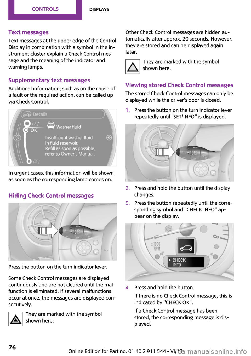
Supplementary text messages Additional information, such as on the cause of
a fault or the required action, can be called up
via Check Control.
In urgent cases, this information will be shown
as soon as the corresponding lamp comes on.
Hiding Check Control messages
Press the button on the turn indicator lever.
Some Check Control messages are displayed
continuously and are not cleared until the mal‐
function is eliminated. If several malfunctions
occur at once, the messages are displayed con‐
secutively.
They are marked with the symbol
shown here.
Other Check Control messages are hidden au‐
tomatically after approx. 20 seconds. However,
they are stored and can be displayed again
later.
They are marked with the symbol
shown here.
Viewing stored Check Control messages The stored Check Control messages can only be
displayed while the driver's door is closed.1.Press the button on the turn indicator lever
repeatedly until "SET/INFO" is displayed.2.Press and hold the button until the display
changes.3.Press the button repeatedly until the corre‐
sponding symbol and "CHECK INFO" ap‐
pear on the display.4.Press and hold the button.
If there is no Check Control message, this is
indicated by "CHECK OK“.
If a Check Control message has been
stored, the corresponding message is dis‐
played.Seite 76ControlsDisplays76
Online Edition for Part no. 01 40 2 911 544 - VI/13
Page 78 of 282

LampsVehicle equipmentThis chapter describes all series equipment as
well as country-specific and special equipment
offered for this model series.Therefore, it also
describes equipment that may not be found in
your vehicle, for instance due to the selected
special equipment or the country version. This
also applies to safety-related functions and sys‐
tems.
At a glance0Lamps off / daytime running lights1Parking lamps and daytime running lights2Low-beam headlamps and welcome lamps3Automatic headlamp control, Adaptive
Light Control, daytime running lights, and
welcome lamps
Parking lamps/low
beams, headlamp con‐
trol
General information
When the driver's door is opened with the igni‐
tion switched off, the exterior lighting is auto‐
matically switched off when the light switch is
in position 0, 2, or 3.
Switch on the parking lamps if necessary,
switch position 1.
Parking lamps Switch position 1: the vehicle lamps light up on
all sides.
Do not use the parking lamps for extended pe‐
riods; otherwise, the battery may become dis‐
charged and it would then be impossible to
start the engine.
When parking, it is preferable to switch on the
one-sided roadside parking lamps, refer to
page 79.
Low beams Switch position 2: the low beams are lit when
the ignition is switched on.
Automatic headlamp control Switch position 3: the low beams are switched
on and off automatically depending on the am‐
bient light, e.g., in tunnels, in twilight, or if
there is precipitation. Adaptive Light Control is
active.
A blue sky with the sun low on the horizon can
cause the lights to be switched on.
The low beams remain switched on independ‐
ent of the ambient lighting conditions when
you switch on the front fog lamps.
Personal responsibility
The automatic headlamp control cannot
serve as a substitute for your personal judg‐
ment in determining when the lamps should be
switched on in response to ambient lighting
conditions.
For example, the sensors are unable to detect
fog or hazy weather. To avoid safety risks, you
should always switch on the lamps manually
under these conditions. ◀Seite 78ControlsLamps78
Online Edition for Part no. 01 40 2 911 544 - VI/13
Page 80 of 282

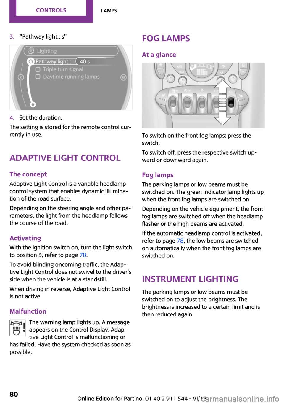
3."Pathway light.: s"4.Set the duration.
The setting is stored for the remote control cur‐
rently in use.
Adaptive Light Control
The concept
Adaptive Light Control is a variable headlamp
control system that enables dynamic illumina‐
tion of the road surface.
Depending on the steering angle and other pa‐
rameters, the light from the headlamp follows
the course of the road.
Activating
With the ignition switch on, turn the light switch
to position 3, refer to page 78.
To avoid blinding oncoming traffic, the Adap‐
tive Light Control does not swivel to the driver's
side when the vehicle is at a standstill.
When driving in reverse, Adaptive Light Control
is not active.
Malfunction The warning lamp lights up. A message
appears on the Control Display. Adap‐
tive Light Control is malfunctioning or
has failed. Have the system checked as soon as
possible.
Fog lamps
At a glance
To switch on the front fog lamps: press the
switch.
To switch off, press the respective switch up‐
ward or downward again.
Fog lamps
The parking lamps or low beams must be
switched on. The green indicator lamp lights up
when the front fog lamps are switched on.
Depending on the vehicle equipment, the front
fog lamps are switched off when the headlamp
flasher or the high beams are activated.
If the automatic headlamp control is activated,
refer to page 78, the low beams are switched
on automatically when the front fog lamps are
switched on.
Instrument lightingThe parking lamps or low beams must be
switched on to adjust the brightness. The
brightness is increased to a certain limit and is
then reduced again.
Seite 80ControlsLamps80
Online Edition for Part no. 01 40 2 911 544 - VI/13