2014 MINI Countryman cargo
[x] Cancel search: cargoPage 115 of 218

5-seater:
The maximum load is the sum of the weight of
the occupants and the cargo.
The greater the weight of the occupants, the
less cargo that can be transported.
Stowing cargo
▷Very heavy cargo: when the rear seat is not
occupied, secure each of the outer safety
belts in the opposite buckle.▷Heavy cargo: stow as far forward and as
low as possible, ideally directly behind the
backrests.▷Cover sharp edges and corners.▷Do not pile cargo higher than the top edge
of the backrests.▷If necessary, fold down the rear backrests
to stow cargo.▷Use the partition net, refer to page 100, to
protect passengers. Make sure that objects
cannot penetrate the partition net.▷Place protective material around any sharp-
edged or pointed objects that could bumpagainst the rear window while the vehicle is
in motion.
MINI Countryman
MINI Paceman
Securing cargo
Lashing eyes in the cargo area
MINI Countryman
Seite 115LoadingDriving tips115
Online Edition for Part no. 01 40 2 911 521 - VI/13
Page 116 of 218

MINI Paceman
Securing cargo
▷Secure smaller and lighter pieces with tight‐
ening belts or straps.▷Secure larger and heavier pieces with cargo
straps.
Adhere to the information included with
the cargo straps.▷Eight mounting eyes are available for fas‐
tening the cargo straps.
Two of them are located on the side wall of
the cargo area, arrows 1, and two are lo‐
cated on the rear wall of the cargo area, ar‐
rows 2.
Securing cargo
Stow and secure the cargo as described
above; otherwise it may present a danger to
the occupants, for instance during braking and
avoidance maneuvers.
Do not stow any heavy and hard objects in the
passenger compartment without securing
them; otherwise, they may present a danger to
occupants, for instance during braking and
avoidance maneuvers.
Never exceed either the approved gross vehicle
weight or either of the approved axle loads, as
excessive loads can pose a safety hazard, and
may also place you in violation of traffic safety
laws.
Do not secure cargo using the upper LATCH
mounting points, refer to page 46; otherwise,
these may become damaged. ◀
Roof-mounted luggage
rack
Notes
A special rack system is available as an optional
accessory.
Attachment Follow the installation instructions for the roof-mounted luggage rack.
Ensure that adequate clearance is available for
the movement of the glass sunroof.
Loading Because roof racks raise the vehicle's center of
gravity when loaded, they have a major effect
on vehicle handling and steering response.
Therefore, note the following when loading and
driving:▷Do not exceed the approved roof/axle
loads and the approved gross vehicle
weight.▷Distribute the roof load uniformly.▷The roof load should not be too large in
area.▷Always load the heaviest pieces on the bot‐
tom.▷Fasten the roof-mounted luggage securely,
for instance using lashing straps.▷Do not let objects project into the opening
path of the tailgate.▷Drive smoothly. Avoid sudden acceleration
and braking maneuvers. Take corners gen‐
tly.
Rear luggage rack
Notes A special rear rack is available as an optional
accessory. It does not require a trailer hitch.
Seite 116Driving tipsLoading116
Online Edition for Part no. 01 40 2 911 521 - VI/13
Page 118 of 218
Saving fuelVehicle equipment
This chapter describes all series equipment as
well as country-specific and special equipment
offered for this model series.Therefore, it also
describes equipment that may not be found in
your vehicle, for instance due to the selected
special equipment or the country version. This
also applies to safety-related functions and sys‐
tems.
General information Your vehicle contains advanced technology for
the reduction of fuel consumption and emis‐
sions.
Fuel consumption depends on a number of dif‐
ferent factors. The implementation of certain
measures, driving style and regular mainte‐ nance can have an influence on fuel consump‐
tion and on the environmental impact.
Remove unnecessary cargo Additional weight increases fuel consumption.
Remove attached parts following use Remove unneeded auxiliary mirrors, roof or
rear luggage racks after use.
Attached parts on the vehicle impair the aero‐
dynamics and increase the fuel consumption.
Close both windows Open windows causes higher air resistance and
thus increases fuel consumption.
Check the tire inflation pressure
regularly
Check and, if necessary, correct the tire infla‐
tion pressure, refer to page 152, at least twice
a month and before starting on a long trip.Low tire inflation pressure increases rolling re‐
sistance and thus raises fuel consumption and
tire wear.
Drive away without delayDo not wait for the engine to warm-up while
the vehicle remains stationary. Start driving
right away, but at moderate engine speeds.
This is the fastest way for the cold engine to
reach its operating temperature.
Look well ahead when driving Avoid unnecessary acceleration and braking. To
achieve this, maintain a suitable distance to the
vehicle driving ahead of you.
Driving smoothly and looking ahead reduces
fuel consumption.
Avoid high engine speeds Use 1st gear to get the vehicle in motion. Be‐
ginning with 2nd gear, accelerate rapidly. When
accelerating, shift up before reaching high en‐
gine speeds.
When you reach the desired speed, shift into
the highest applicable gear and drive with the
engine speed as low as possible and at a con‐
stant speed.
As a rule: driving at low engine speeds lowers
fuel consumption and reduces wear.
Use coasting conditions
When approaching a red light, take your foot
off the accelerator and coast to a halt in the
highest applicable gear.
On a downhill slope, take your foot off the ac‐
celerator and coast in a suitable gear.
The flow of fuel is interrupted while coasting.Seite 118Driving tipsSaving fuel118
Online Edition for Part no. 01 40 2 911 521 - VI/13
Page 149 of 218
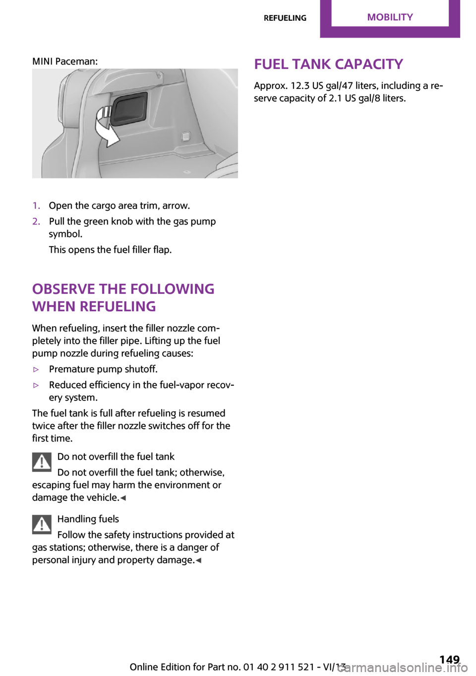
MINI Paceman:
1.Open the cargo area trim, arrow.2.Pull the green knob with the gas pump
symbol.
This opens the fuel filler flap.
Observe the following
when refueling
When refueling, insert the filler nozzle com‐
pletely into the filler pipe. Lifting up the fuel
pump nozzle during refueling causes:
▷Premature pump shutoff.▷Reduced efficiency in the fuel-vapor recov‐
ery system.
The fuel tank is full after refueling is resumed
twice after the filler nozzle switches off for the
first time.
Do not overfill the fuel tank
Do not overfill the fuel tank; otherwise,
escaping fuel may harm the environment or
damage the vehicle. ◀
Handling fuels
Follow the safety instructions provided at
gas stations; otherwise, there is a danger of
personal injury and property damage. ◀
Fuel tank capacity
Approx. 12.3 US gal/47 liters, including a re‐
serve capacity of 2.1 US gal/8 liters.Seite 149RefuelingMobility149
Online Edition for Part no. 01 40 2 911 521 - VI/13
Page 162 of 218

3.Insert the sealant bottle into the compres‐
sor housing in a vertical position.4.Unscrew the dust cap off of the valve of the
defective wheel and screw the filling hose 2
of the sealant bottle onto the valve.5.Ensure that the compressor is switched off.6.Insert connector 5 into the lighter socket/
socket in the passenger compartment, refer
to page 97.7.When the engine is running:
Switch on the compressor and let it run for
approx. 3 to 8 minutes to fill sealant into
the tire and achieve a tire inflation pressure
of approx. 1.8 bar/26 psi.
While sealant is being filled, the inflation
pressure may intermittently rise to approx.
5 bar/73 psi. Do not switch off the com‐
pressor in this phase.8.Switch off the compressor.
Do not allow the compressor to run too
long
Do not allow the compressor to run longer than
10 minutes; otherwise, the device will overheat
and may be damaged. ◀
If an air pressure of 1.8 bar/26 psi is not
reached:
1.Unscrew the filling hose 2 from the wheel
and drive forward and back approx.
33 ft/10 m to evenly distribute the sealant
in the tire.2.Inflate the tire again using the compressor.If the inflation pressure of 1.8 bar/26 psi is still
not reached, the tire is too heavily damaged.
Contact the nearest service center.
Stowing the Mobility System1.Unscrew the filling hose 2 of the sealant
bottle from the wheel.2.Unscrew the compressor connection hose 6
from the sealant bottle.3.Connect the filling hose 2 of the sealant
bottle with the free connector on the seal‐
ant bottle.
This prevents left-over sealant from escap‐
ing from the bottle.4.Wrap the empty sealant bottle in suitable
material to avoid dirtying the cargo area.5.Stow the Mobility System back in the vehi‐
cle.
Distributing the sealant
Drive approx. 3.1 miles/5 km to evenly distrib‐
ute the sealant.
Do not exceed a speed of 50 mph/80 km/h. If
possible, do not drop below a speed of
10 mph/20 km/h.
Correcting the tire inflation pressure
1.After driving approx. 3.1 miles/5 km, or
about 10 minutes, stop in a suitable loca‐
tion.2.Screw the connection hose 6 of the com‐
pressor directly onto the tire valve.3.Insert the connector 5 into the power
socket in the passenger compartment.4.Correct the tire inflation pressure to
1.8 bar/26 psi. When the engine is running:▷To increase the inflation pressure:
switch on the compressor. To check the
currently set inflation pressure, switch
off the compressor.▷To reduce the inflation pressure: press
the release button 9.Seite 162MobilityWheels and tires162
Online Edition for Part no. 01 40 2 911 521 - VI/13
Page 175 of 218

Lateral turn signals
5-watt bulb, W 5 W1.Open the hood.2.Squeeze the clip, arrows, and remove the
bulb holder.3.Remove the bulb by turning it to the left
and replace it.4.Insert the new bulb and attach the cover in
reverse order.
Side marker lamps
To replace these bulbs, contact the service cen‐
ter.
Tail lamps, bulb replacement Follow the general instructions on lamps and
bulbs, refer to page 172.
Turn signal: 21-watt bulb, PY 21 W
MINI Countryman
1Brake/tail lamp2Turn signal3Brake/tail lamp4Backup lamp
MINI Paceman
1Brake lamp2Tail lamp3Turn signal4Backup lamp
Replacing
All bulbs are integrated in a central bulb holder.
MINI Countryman
1.Switch off the lamps and take the remote
control out of the ignition lock.2.Open the tailgate.3.Press the cover out of the cargo area side
panel at the rear and remove it.4.Detach the emergency release of the fuel
filler flap, refer to page 148, and push it
aside with the foam insert.
Ensure that the emergency release is not
damaged.Seite 175Replacing componentsMobility175
Online Edition for Part no. 01 40 2 911 521 - VI/13
Page 176 of 218

5.Disengage the bulb holder by pushing
down the clip, arrow 1.6.Take out the bulb holder and detach the
cable, arrow 2.7.Apply gentle pressure to the bulb while
turning it to the left and remove it.8.Insert the new bulb and mount the bulb
holder in reverse order. Ensure that the
bulb holder engages in all fasteners.9.Return the foam insert to its original posi‐
tion and reattach the emergency release of
the fuel filler flap.10.Reattach the cover.
MINI Paceman
1.Switch off the lamps and take the remote
control out of the ignition lock.2.Open the tailgate.3.Remove the cover from the cargo area side
trim.4.Unlock the fastening elements, arrows 1, by
turning.5.Remove the screws, arrows 2, using the hex
key from the vehicle document portfolio.6.Remove the tail lamp.7.Disengage the bulb holder by pushing
down the clip, arrows 1.8.Take out the bulb holder and detach the
cable, arrow 2.9.Apply gentle pressure to the bulb while
turning it to the left and remove it.10.Insert the new bulb and mount the bulb
holder in reverse order. Ensure that the
bulb holder engages in all fasteners.
License plate lamps
5-watt bulb, C 5 W
Seite 176MobilityReplacing components176
Online Edition for Part no. 01 40 2 911 521 - VI/13
Page 180 of 218

Breakdown assistanceVehicle equipment
This chapter describes all series equipment as
well as country-specific and special equipment
offered for this model series.Therefore, it also
describes equipment that may not be found in
your vehicle, for instance due to the selected
special equipment or the country version. This
also applies to safety-related functions and sys‐
tems.
Hazard warning flash‐
ers
The button is located on the speedometer.
Warning triangle
Under the loading edge in the cargo area.
To remove, open the two fasteners.
First aid kit
Some of the articles contained in the first aid kit
have a limited service life. Therefore, check the
use-by dates of the contents regularly and re‐
place the items before they expire.
The first aid kit is located in the left side trim on
the cargo area floor or under the loading floor.
Roadside Assistance Service availability
Roadside Assistance can be reached around the
clock in many countries. You can obtain assis‐
tance there in the event of a vehicle break‐
down.
Roadside Assistance A phone number for Roadside Assistance can
be displayed, refer to page 142, via the radio.
Jump-starting NotesIf the battery is discharged, the engine can be
started using the battery of another vehicle and
two jumper cables. In the same way, you can
help jump-start another vehicle. Only use
Seite 180MobilityBreakdown assistance180
Online Edition for Part no. 01 40 2 911 521 - VI/13