2014 MINI Clubman remote control
[x] Cancel search: remote controlPage 57 of 276

Turn signal, high beams,
headlamp flasher1Turn signal2Switching on the high beams3Switching off the high beams/headlamp
flasher
Turn signal
Press the lever beyond the resistance point.
To switch off manually, press the lever to the
resistance point.
Unusually rapid flashing of the indicator lamp
indicates that a turn signal bulb has failed.
Signaling a turn briefly Press the lever to the resistance point and hold
it there for as long as you want the turn signal
to flash.
Triple turn signal activation Press the lever to the resistance point.
The turn signal flashes three times.
This function can be activated or deactivated:
1."Settings"2."Lighting"3."Triple turn signal"
The setting is stored for the remote control cur‐
rently in use.
Washer/wiper system
Notes Do not switch on the wipers if frozen
Do not switch on the wipers if they are
frozen onto the windshield; otherwise, the
wiper blades and the windshield wiper motor
may be damaged. ◀
Do not use the wipers on a dry windshield
Do not use the wipers on a dry wind‐
shield; otherwise, the wiper blades may wear
more rapidly or become damaged. ◀
At a glance
1Switching on wipers2Switching off wipers or brief wipeSeite 57DrivingControls57
Online Edition for Part no. 01 40 2 911 452 - VI/13
Page 61 of 276

Reverse gearSelect only when the vehicle is stationary. When
the gearshift lever is pressed to the left, a slight
resistance needs to be overcome.
Automatic transmission
with Steptronic
In addition to the fully automatic mode, gears
can also be shifted manually using Steptronic,
refer to page 62.
Parking the vehicle Secure the vehicle
Before leaving the vehicle with the en‐
gine running, move the selector lever to posi‐
tion P and set the handbrake; otherwise, the
vehicle will begin moving. ◀
Disengaging the remote control
To remove the remote control from the ignition
lock, first move the selector lever to position P
and switch off the engine: interlock. Remove
the remote control from the ignition lock, refer
to page 54.
Selector lever positions
P R N D M/S + –
Displays in the tachometer
The selector lever position is displayed and the
engaged gear, such as M4, is displayed in
manual mode.
Changing selector lever positions▷With the ignition switched on or the engine
running, the selector lever can be moved
out of position P.▷When the vehicle is stationary, step on the
brake before shifting out of P or N; other‐
wise, the selector lever is locked: shiftlock.
Press on the brake pedal until you
start driving
To prevent the vehicle from creeping after
you select a driving position, maintain pres‐
sure on the brake pedal until you are ready
to start. ◀
A lock prevents accidental shifting into selector
lever positions R and P.
To override the lock, press the button on the
front of the selector lever, see arrow.
P Park
Select only when the vehicle is stationary. The
front wheels are blocked.
R is Reverse
Select only when the vehicle is stationary.
N is NeutralFor example, engage this position in a car
wash. The vehicle can roll.
D Drive, automatic position Position for normal vehicle operation. All for‐
ward gears are selected automatically.
Seite 61DrivingControls61
Online Edition for Part no. 01 40 2 911 452 - VI/13
Page 68 of 276

Next setting or information1.Within a setting or information display,
press the button on the turn indicator lever
repeatedly until "NEXT" is displayed.2.Hold the button down.
Direct change to the next setting or piece of in‐
formation.
Units of measure
The units of measure, such as for fuel consump‐
tion, route/distance, and temperature, can be
changed. The settings are stored for the remote
control currently in use.
1."Settings"2."Language/Units"3.Select the desired menu item.4.Select the desired unit.Clock
Setting the time1."Settings"2."Time/Date"3."Time:"4.Turn the MINI joystick to set the hours and
press the MINI joystick.5.Turn the MINI joystick to set the minutes
and press the MINI joystick.
The time is stored.
Setting the time format
1."Settings"2."Time/Date"Seite 68ControlsDisplays68
Online Edition for Part no. 01 40 2 911 452 - VI/13
Page 69 of 276

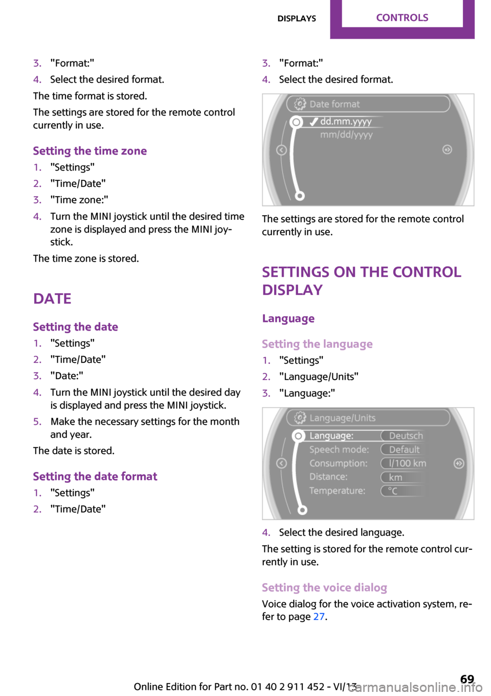
3."Format:"4.Select the desired format.
The time format is stored.
The settings are stored for the remote control
currently in use.
Setting the time zone
1."Settings"2."Time/Date"3."Time zone:"4.Turn the MINI joystick until the desired time
zone is displayed and press the MINI joy‐
stick.
The time zone is stored.
Date
Setting the date
1."Settings"2."Time/Date"3."Date:"4.Turn the MINI joystick until the desired day
is displayed and press the MINI joystick.5.Make the necessary settings for the month
and year.
The date is stored.
Setting the date format
1."Settings"2."Time/Date"3."Format:"4.Select the desired format.
The settings are stored for the remote control
currently in use.
Settings on the Control Display
Language
Setting the language
1."Settings"2."Language/Units"3."Language:"4.Select the desired language.
The setting is stored for the remote control cur‐
rently in use.
Setting the voice dialog Voice dialog for the voice activation system, re‐
fer to page 27.
Seite 69DisplaysControls69
Online Edition for Part no. 01 40 2 911 452 - VI/13
Page 70 of 276

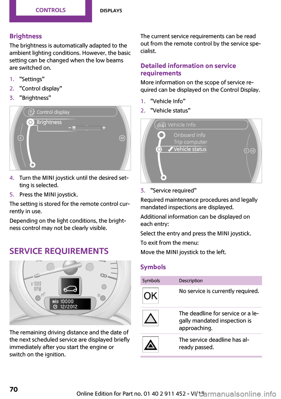
Brightness
The brightness is automatically adapted to the
ambient lighting conditions. However, the basic
setting can be changed when the low beams
are switched on.1."Settings"2."Control display"3."Brightness"4.Turn the MINI joystick until the desired set‐
ting is selected.5.Press the MINI joystick.
The setting is stored for the remote control cur‐
rently in use.
Depending on the light conditions, the bright‐
ness control may not be clearly visible.
Service requirements
The remaining driving distance and the date of
the next scheduled service are displayed briefly
immediately after you start the engine or
switch on the ignition.
The current service requirements can be read
out from the remote control by the service spe‐
cialist.
Detailed information on service
requirements
More information on the scope of service re‐
quired can be displayed on the Control Display.1."Vehicle Info"2."Vehicle status"3."Service required"
Required maintenance procedures and legally
mandated inspections are displayed.
Additional information can be displayed on
each entry:
Select the entry and press the MINI joystick.
To exit from the menu:
Move the MINI joystick to the left.
Symbols
SymbolsDescriptionNo service is currently required.The deadline for service or a le‐
gally mandated inspection is
approaching.The service deadline has al‐
ready passed.Seite 70ControlsDisplays70
Online Edition for Part no. 01 40 2 911 452 - VI/13
Page 75 of 276

When the daytime running lights are activated,
the low beams are always switched on in
switch position 3 when the ignition is switched
on.
The exterior lighting goes out automatically af‐
ter the vehicle is switched off.
High beams/roadside parking lamps1Turn signal/roadside parking lamp2Switching on the high beams3Switching off the high beams/headlamp
flasher
To assist in parking, the vehicle can be illumi‐
nated on one side; note the country-specific
regulations.
The roadside parking lamps drain the battery.
Therefore, do not leave them on for unduly
long periods of time; otherwise, the battery
might not have enough power to start the en‐
gine.
Switching on the roadside parking lamp
To switch on the roadside parking lamp on the
left or right, press the turn indicator lever up or
down after switching off the vehicle, arrow 1.
Switching off the roadside parking lamp
Press the lever up or down to the resistance
point.
Daytime running lights
The daytime running lights light up in switch
position 0, 1, or 3 when the ignition is switched
on.
The exterior lighting goes out automatically af‐
ter the vehicle is switched off.
In switch position 1, the parking lamps light up
after the ignition is switched off.
Activating/deactivating1."Settings"2."Lighting"3."Daytime running lamps"
The setting is stored for the remote control cur‐
rently in use.
Welcome lamps If the light switch stays in switch position 2 or 3
after the vehicle is switched off, the parking
lamps and the interior lamps light up for a cer‐
tain period when the vehicle is unlocked.
Headlamp courtesy delay feature The low beams stay lit for a short while after
the ignition is switched off, if the lamps are
switched off and the headlamp flasher is
switched on.
Setting the duration
1."Settings"2."Lighting"Seite 75LampsControls75
Online Edition for Part no. 01 40 2 911 452 - VI/13
Page 76 of 276

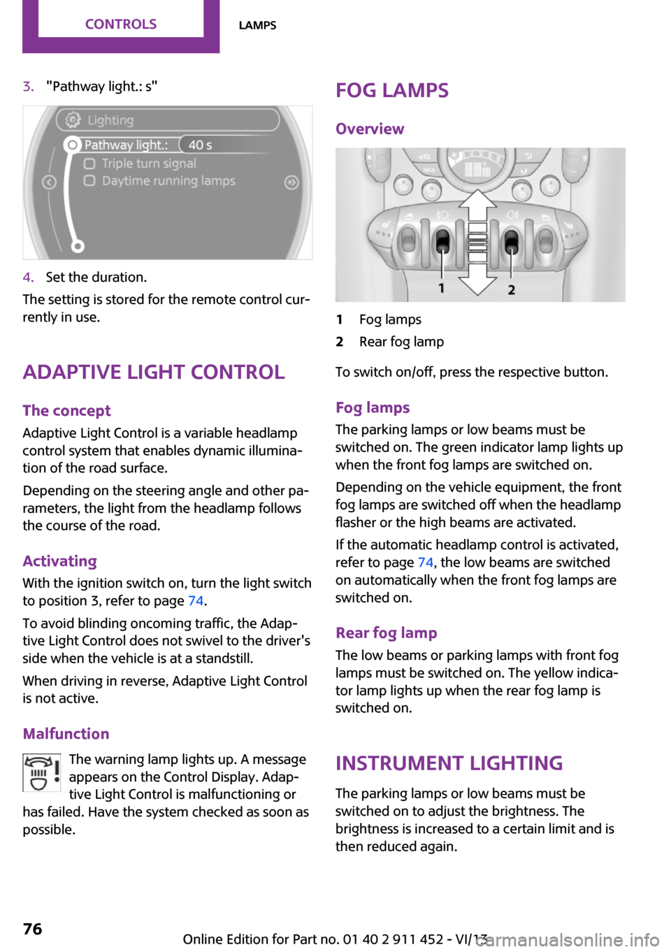
3."Pathway light.: s"4.Set the duration.
The setting is stored for the remote control cur‐
rently in use.
Adaptive Light Control
The concept
Adaptive Light Control is a variable headlamp
control system that enables dynamic illumina‐
tion of the road surface.
Depending on the steering angle and other pa‐
rameters, the light from the headlamp follows
the course of the road.
Activating
With the ignition switch on, turn the light switch
to position 3, refer to page 74.
To avoid blinding oncoming traffic, the Adap‐
tive Light Control does not swivel to the driver's
side when the vehicle is at a standstill.
When driving in reverse, Adaptive Light Control
is not active.
Malfunction The warning lamp lights up. A message
appears on the Control Display. Adap‐
tive Light Control is malfunctioning or
has failed. Have the system checked as soon as
possible.
Fog lamps
Overview1Fog lamps2Rear fog lamp
To switch on/off, press the respective button.
Fog lamps
The parking lamps or low beams must be
switched on. The green indicator lamp lights up
when the front fog lamps are switched on.
Depending on the vehicle equipment, the front
fog lamps are switched off when the headlamp
flasher or the high beams are activated.
If the automatic headlamp control is activated,
refer to page 74, the low beams are switched
on automatically when the front fog lamps are
switched on.
Rear fog lamp
The low beams or parking lamps with front fog
lamps must be switched on. The yellow indica‐
tor lamp lights up when the rear fog lamp is
switched on.
Instrument lightingThe parking lamps or low beams must be
switched on to adjust the brightness. The
brightness is increased to a certain limit and is
then reduced again.
Seite 76ControlsLamps76
Online Edition for Part no. 01 40 2 911 452 - VI/13
Page 96 of 276

Microfilter
The microfilter traps dust and pollen. The mi‐
crofilter is changed by the service center during
routine maintenance work.
Microfilter/activated-charcoal filter
The microfilter traps dust and pollen. The acti‐
vated-charcoal filter provides additional protec‐tion by filtering gaseous pollutants from the
outside air. The service center replaces this
combined filter during routine maintenance.
Automatic climate control
1Air volume, manual2AUTO program3Recirculated air mode4Maximum cooling5Manual air distribution6Temperature7Defrosting windows and removing conden‐
sation8Cooling function9Rear window defroster10Windshield heatingComfortable interior climate
The AUTO program offers the optimum air dis‐tribution and air volume for virtually all condi‐
tions, refer to AUTO program below. Select a
comfortable interior temperature only.The following sections contain more detailed
information on the available setting options.
Most of these settings are stored for the remote
control in use, Personal Profile settings, refer to
page 33.Seite 96ControlsClimate96
Online Edition for Part no. 01 40 2 911 452 - VI/13