2014 MERCEDES-BENZ M-Class trailer hitch
[x] Cancel search: trailer hitchPage 9 of 462

Car wash (care)
................................. 370
CD player/CD changer (on-board
computer) .......................................... 270
Center console Lowe rsection .................................. 37
Uppe rsection .................................. 36
Central locking
Automatic locking (on-board
computer) ...................................... 276
Locking/unlocking (SmartKey) ........80
Changing bulbs
Brake lamps ................................... 132
High-beam headlamps ...................131
Important safety notes ..................129
Low-beam headlamps ....................130
Overview of bul btypes .................. 129
Parking lamps ................................ 131
Removing/replacing the cover
(front wheel arch) .......................... 130
Side marker lamps .........................131
Standing lamps (front) ...................131
Child-proof locks
Important safety notes ....................65
Rea rdoors ....................................... 66
Children
In the vehicle ................................... 60
Restraint systems ............................ 60
Specia lseat belt retractor ...............63
Child seat
LATCH-type (ISOFIX) child seat
anchors ............................................ 63
Top Tether ....................................... 64
Cigarette lighter ................................ 346
Cleaning Mirro rturn signal ........................... 373
Trailer tow hitch ............................. 374
Climate control
Automatic climate control (3-zone) 142
Controlling automatically ...............146
Cooling with aird ehumidification..145
Defrosting the windows .................150
Defrosting the windshield ..............149
Dual-zone automatic climate
control ........................................... 139
Important safety notes ..................138
Indicator lamp ................................ 146
Information on using 3-zone
automatic climate control ..............144 Maximum cooling
.......................... 149
Notes on using dual-zone
automatic climate control ..............141
Overview of systems ......................138
Problems with cooling with air
dehumidification ............................ 146
Problem with the rear window
defroster ........................................ 151
Rea rcontrol panel ......................... 142
Refrigerant ..................................... 451
Refrigerant filling capacity .............452
Setting the aird istribution.............148
Setting the airflow .........................148
Setting the airv ents...................... 152
Setting the climate mode (AIR
FLOW) ............................................ 147
Setting the temperature ................147
Switching air-recirculation mode
on/off ............................................ 151
Switching on/off ........................... 144
Switching residual hea ton/off ......151
Switching the rear window
defroster on/off ............................ 150
Switching the ZONE function on/
off .................................................. 149
Coat hooks ......................................... 340
Cockpit Overview .......................................... 32
see Instrument cluster
COLLISIO NPREVENTION ASSIST
Operation/note s.............................. 69
COMAND
ON&OFFROAD menu .....................252
see separate operating instructions
COMAND display
Cleaning ......................................... 375
Combination switch ..........................123
Combine dcargo cover and net ........339
Consumption statistics (on-board
computer) .......................................... 266
Convenience closing feature ..............95
Convenience opening feature ............95
Coolan t(engine)
Checkin gthe level ......................... 367
Display message ............................ 298
Filling capacity ............................... 451
Important safety notes ..................450
Temperature (on-board computer) .278 Index
7
Page 22 of 462

Direction of rotatio
n...................... 422
Display message ............................ 310
Distributio nofthe vehicle
occupants (definition) ....................421
DOT, Tire Identification Number
(TIN) .............................................. .418
DOT (Department of
Transportation) (definition) ............419
GAWR (Gross Axle Weight Rating)
(definition) ..................................... 419
GTW (Gross Trailer Weight)
(definition) ..................................... 419
GVW (Gross Vehicle Weight)
(definition) ..................................... 419
GVWR (Gross Vehicle Weight
Rating) (definition) .........................419
Important safety notes ..................398
Increased vehicle weight due to
optional equipment (definition) ......419
Kilopascal (kPa) (definition) ...........419
Labeling (overview )........................ 415
Load bearing index (definition) ......420
Load index ..................................... 417
Load index (definition) ...................420
M+S tires ....................................... 400
Maximum loaded vehicle weight
(definition) ..................................... 419
Maximum load on a tire (definition) 420
Maximum permissible tire
pressure (definition) ....................... 420
Maximum tire loa d......................... 417
Maximum tire load (definition) .......420
MOExtended tires ..........................400
Optional equipment weight
(definition) ..................................... 420
PSI (pounds per square inch)
(definition) ..................................... 420
Replacing ....................................... 421
Service life ..................................... 400
Sidewall (definition) .......................420
Speed rating (definition) ................419
Storing ........................................... 422
Structure and characteristics
(definition) ..................................... 418
Temperature .................................. 414
TIN (Tire Identification Number)
(definition) ..................................... 420
Tire bea d(definition) ...................... 420Tire pressure (definition)
................420
Tire pressures (recommended )...... 419
Tire size (data) ............................... 426
Tire size designation, load-bearing
capacity, speed rating .................... 415
Tire tread ....................................... 399
Tire tread (definition) .....................420
Total load limit (definition) .............421
Traction ......................................... 414
Traction (definition) .......................421
Trea dwear ..................................... 414
TWR (permissible trailer drawbar
noseweight) (definition) .................421
Uniform Tire Quality Grading
Standard s...................................... 413
Uniform Tire Quality Grading
Standard s(definition) .................... 419
Unladen weight (definition) ............420
Wea rindicato r(definition) .............421
Whee lrim (definition ).................... 419
see Flat tire
Tool
see Vehicle tool kit
Top Tether ............................................ 64
Towing Important safety guidelines ...........391
Installing the towing eye ................392
Removing the towing eye. ..............393
With the rear axle raised ................393
Towing atrailer
Activ eParking Assist ..................... 220
Axle load, permissible ....................456
Cleaning the trailer tow hitch ......... 374
Coupling up atrailer ...................... 256
Decoupling atrailer ....................... 258
Driving tips .................................... 253
ESP ®
(Electronic Stability Program) .73
Important safety notes ..................253
Installing the ball coupling .............255
Mounting dimensions ....................455
Power supply ................................. 259
Pulling away with a trailer ..............160
Removing the ball coupling ............259
Storing the ball coupling ................259
Trailer drive program .....................245
Trailer loads ................................... 456
Towing away
With both axles on the ground .......393 20
Index
Page 217 of 462
yellow segments showing operational
readiness 0023ligh tup.
The selected transmission position and the
direction in which the vehicle is rolling
determine which warning display is active
when the engine is running. Transmission
position Warning display
D
Front area activated
R,
Nor the vehicle
is rolling
backwards Rear and front areas
activated
P
No areas activated
One or more segments light up as the vehicle
approaches an obstacle, dependin gonthe
vehicle's distance from the obstacle.
From the:
R sixth segment onwards, you will hear an
intermittent warning tone for
approximately two seconds.
R seventh segment onwards, you will hear a
warning tone for approximately two
seconds. This indicates that you have now
reached the minimum distance.
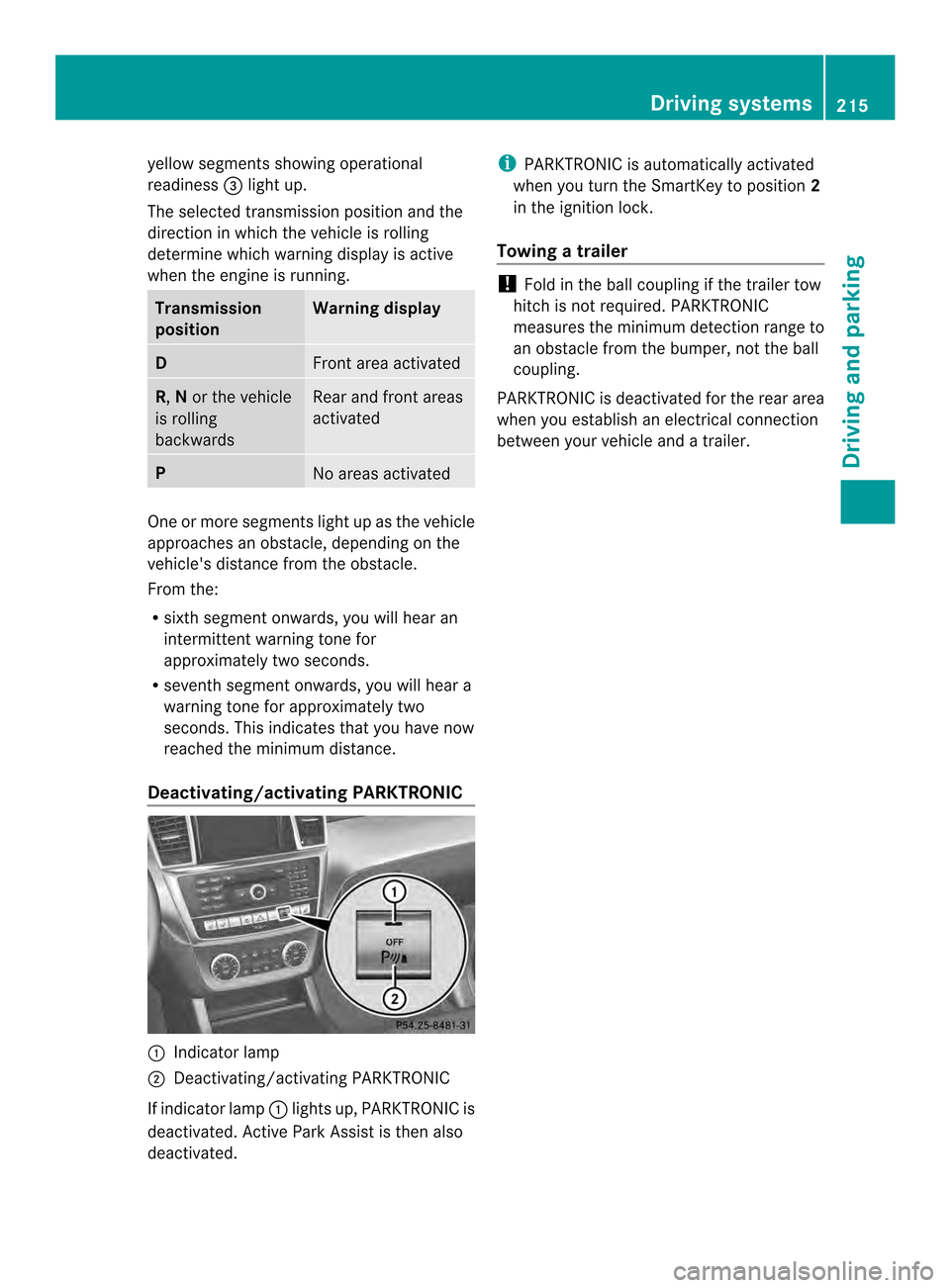
Deactivating/activating PARKTRONIC 0002
Indicator lamp
0003 Deactivating/activating PARKTRONIC
If indicator lamp 0002lights up, PARKTRONIC is
deactivated. Active Park Assist is then also
deactivated. i
PARKTRONIC is automatically activated
when you turn the SmartKey to position 2
in the ignition lock.
Towing atrailer !
Fold in the ball coupling if the trailer tow
hitch is not required .PARKTRONIC
measures the minimu mdetection range to
an obstacle from the bumper, not the ball
coupling.
PARKTRONIC is deactivated for the rear area
when you establish an electrical connection
between your vehicle and a trailer. Driving systems
215Driving and parking Z
Page 222 of 462
Once you have exited the parking space
completely, the steering wheel is moved to
the straight-ahead position. You hear a tone
and the
Park Assist Switched Off message appears in the multifunction
display. You will then have to steer and merge
into traffic on your own. PARKTRONIC is still
available. You can take over the steering,
before the vehicle has exited the parking
space completely. This is useful, for example
when you recognize that it is already possible
to pull out of the parking space.
Canceling Active Parking Assist
X
Stop the movement of the multifunction
steering wheel or steer yourself.
Active Parking Assist will be canceled at
once. The Park Assist Canceled message appears in the multifunction
display.
or
X Press the PARKTRONIC button on the
center console (Y page 215).
PARKTRONIC is switched off and Active
Parking Assist is immediately canceled.
The Park Assist Canceled message
appears in the multifunction display.
Active Parking Assist is canceled
automatically if:
R the electric parking brake is engaged
R transmission position Pis selected
R parking using Active Parking Assist is no
longer possible
R you are driving faster than 6 mph
(10 km/h)
R a wheel spins, ESP ®
intervenes or fails. The
000F warning lamp lights up in the
instrument cluster.
Aw arning tone sounds. The parking symbol
disappears and the multifunction display
shows the Park Assist Canceled message.
If Active Parking Assist is canceled, you must
steer again yourself. Towing
atrailer For vehicles with a trailer tow hitch, the
minimum length for parking spaces is slightly
increased.
If you have attached a trailer to your vehicle,
you should not use Active Parking Assist.
Once the electrical connectio
nis established
between your vehicle and the trailer, Active
Parking Assist is no longer available.
PARKTRONIC is deactivated for the rear area. Rear view camera
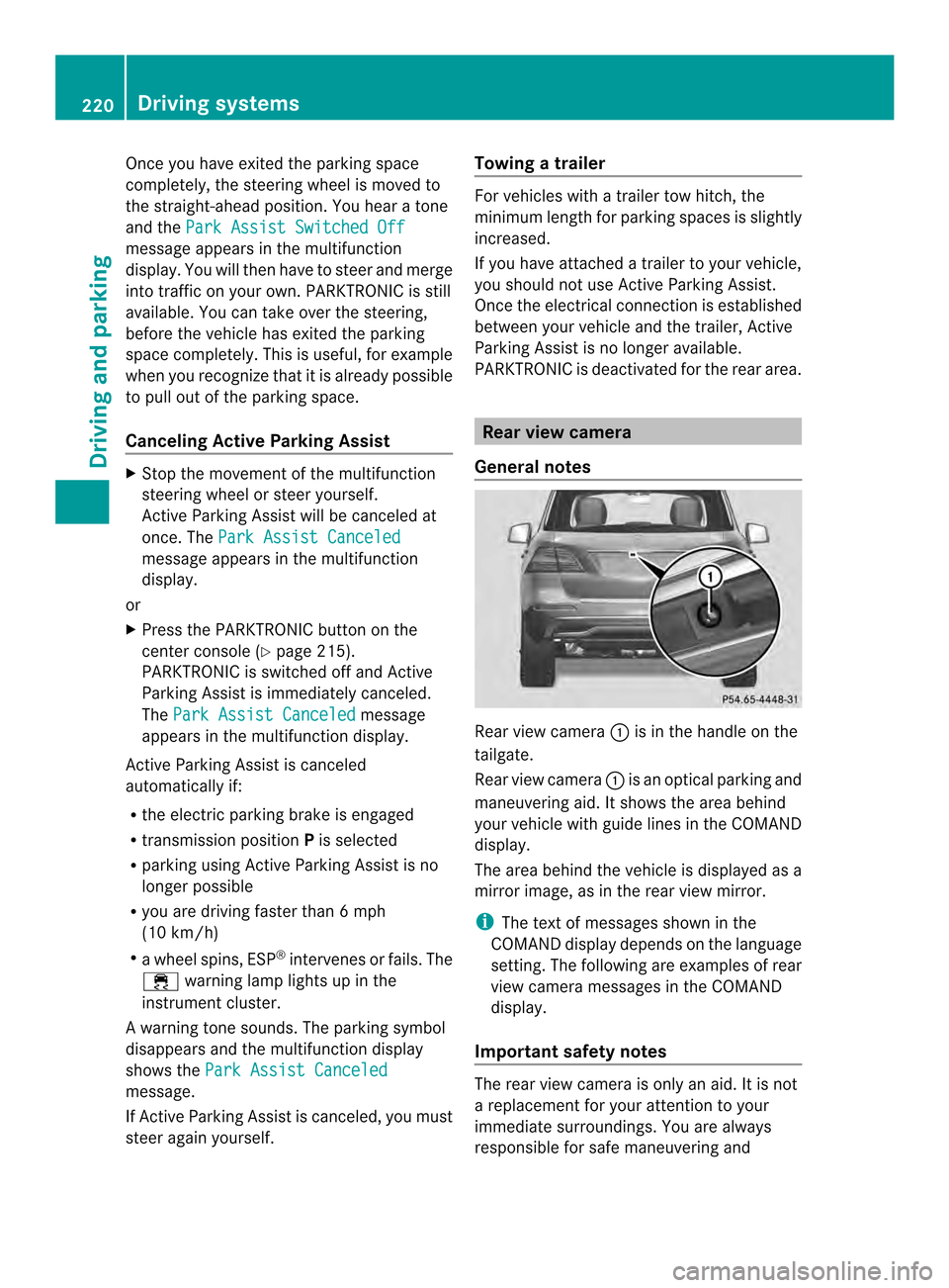
General notes Rear view camera
0002is in the handle on the
tailgate.
Rear view camera 0002is an optical parking and
maneuvering aid. It shows the area behind
your vehicle with guide lines in the COMAND
display.
The area behind the vehicle is displayed as a
mirror image, as in the rear view mirror.
i The text of messages shown in the
COMAND display depends on the language
setting. The following are examples of rear
view camera messages in the COMAND
display.
Important safety notes The rear view camera is only an aid. It is not
a replacement for your attention to your
immediate surroundings. You are always
responsible for safe maneuvering and220
Driving systemsDriving and parking
Page 223 of 462
parking. When maneuvering or parking, make
sure that there are no persons, animals or
objects in the area in which you are
maneuvering.
Under the following circumstances, the rear
view camera will not function, or will function
in a limited manner:
R the tailgate is open
R in heavy rain, snow or fog
R at night or in very dark places
R if the camera is exposed to very bright light
R if the area is lit by fluorescent light or LED
lighting (the display may flicker)
R if there is a sudden change in temperature,
e.g. when driving into a heated garage in
winter
R if the camera lens is dirty or obstructed
R if the rear of your vehicle is damaged. In
this event, have the camera position and
setting checked at a qualified specialist
workshop
Activating/deactivating the rear view
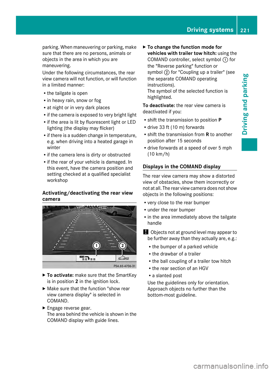
camera X
To activate: make sure that the SmartKey
is in position 2in the ignition lock.
X Make sure that the function "show rear
view camera display" is selected in
COMAND.
X Engage reverse gear.
The area behind the vehicle is shown in the
COMAND display with guide lines. X
To change the function mode for
vehicles with trailer tow hitch: using the
COMAND controller, select symbol 0002for
the "Reverse parking" function or
symbol 0003for "Coupling up a trailer" (see
the separate COMAND operating
instructions).
The symbol of the selected function is
highlighted.
To deactivate: the rear view camera is
deactivated if you:
R shift the transmission to position P
R drive 33 ft (10 m) forwards
R shift the transmission from Rto another
position after 15 seconds
R drive forwards at a speed of over 5mph
(10 km/h)
Displays in the COMAND display The rear view camera may show a distorted
view of obstacles, show them incorrectly or
not at all. The rear view camera does not show
objects in the following positions:
R
very close to the rear bumper
R under the rear bumper
R in the area immediately above the tailgate
handle
! Objects not at ground level may appear to
be further away than they actually are, e.g.:
R the bumper of a parked vehicle
R the drawbar of a trailer
R the ball coupling of a trailer tow hitch
R the rear section of an HGV
R a slanted post
Use the guidelines only for orientation.
Approach objects no further than the
bottom-most guideline. Driving systems
221Driving and parking Z
Page 226 of 462
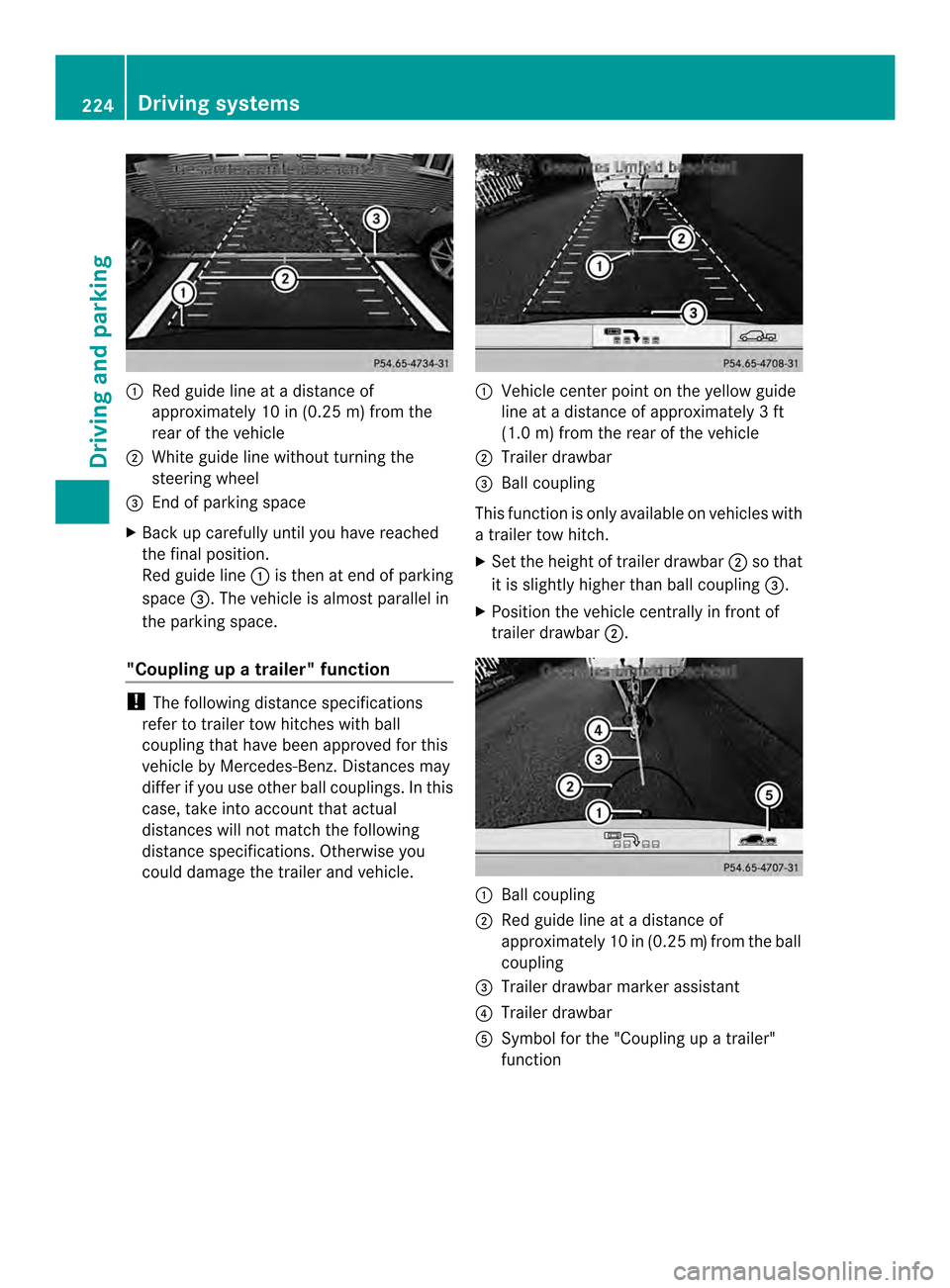
0002
Red guide line at a distanc eof
approximately 10 in (0.25 m) from the
rear of the vehicle
0003 White guide line without turning the
steering wheel
0023 End of parking space
X Bac kup carefully until you have reached
the final position.
Red guide line 0002is then at end of parking
space 0023.The vehicle is almost parallel in
the parking space.
"Coupling up a trailer" function !
The following distance specifications
refer to trailer tow hitches with ball
coupling that have been approved for this
vehicle by Mercedes-Benz. Distances may
differ if you use other ball couplings. In this
case, take into account that actual
distances will not match the following
distance specifications. Otherwise you
could damage the trailer and vehicle. 0002
Vehicle center point on the yellow guide
line at a distance of approximately 3ft
(1.0 m) from the rear of the vehicle
0003 Trailer drawbar
0023 Ball coupling
This function is only available on vehicles with
a trailer tow hitch.
X Set the height of trailer drawbar 0003so that
it is slightly higher than ball coupling 0023.
X Position the vehicle centrally in fron tof
trailer drawbar 0003. 0002
Ball coupling
0003 Red guide line at a distance of
approximately 10 in (0.25 m)from the ball
coupling
0023 Trailer drawbar marker assistant
0022 Trailer drawbar
0020 Symbol for the "Coupling up a trailer"
function 224
Driving systemsDriving and parking
Page 227 of 462
X
Use the COMAND controller to select
symbol 0020, see the separate operating
instructions for COMAND.
The "Coupling up a trailer" function is
selected. The distance specifications now
only apply to objects that are at the same
level as the ball coupling.
X Back up carefully, making sure that trailer
drawbarm arker assistant 0023points
approximately in the direction of trailer
drawbar 0022.
X Reverse carefully until trailer drawbar 0022
reaches red guide line 0003.
X Couple up the trailer (Y page 253).360° camera (surround view)
General notes The 360° camera is a system consisting of
four cameras.
The system analyzes images from the
following cameras:
R Rear view camera
R Front camera
R Two cameras in the exterior rear view
mirrors
The cameras capture the immediate
surroundings of the vehicle .The system
supports you, e.g. when parking or if vision is
restricted at an exit.
The 360° camera images can be shown in full
screen mode or in seven different split-screen
views on the COMAND display. Asplit-screen
view also includes a top view of the vehicle.
This view is calculated from the data supplied
by the installed cameras (virtual camera).
The seven split-screen views are:
R top view and picture from the rear view
camera (130 °viewing angle)
R top view and picture fro mthe front camera
(without displaying the maximum steering
wheel angle)
R top view and enlarged rear view R
top view and enlarged front view
R top view and trailer view (vehicles with
trailer tow hitch)
R top view and pictures from the rearward
facing mirror cameras (rear wheel view)
R top view and pictures from the forward
facing mirror cameras (front wheel view)
i The top view and trailer view are available
for vehicles equipped with a trailer tow
hitch.
When the function is active and you shift the
transmission from position Dor Rto N, you
see the previous view in the COMAND
display. The dynamic guidelines are hidden.
When you change between transmission
positions Dand R, you see the previously
selected front or rear view.
Important safety notes The 360° camera is only an aid. It is not a
replacement for your attention to your
immediate surroundings. You are always
responsible for safe maneuvering and
parking. When maneuvering or parking, make
sure that there are no persons, animals or
objects in the area in which you are
maneuvering.
The 360° camera may show a distorted view
of obstacles, show them incorrectly or not at
all. It cannot show objects in the following
areas:
R
under the front bumper
R very close to the front bumper
R very close to the rear bumper
R under the rear bumper
R in close range above the handle on the
trunk lid
R very close to the exterior mirrors
You are always responsible for safety, and
must always pay attention to your
surroundings when parking and
maneuvering. This applies to the areas
behind, in front of and beside the vehicle. You Driving systems
225Driving and parking Z
Page 229 of 462

X
To switc hto full screen mode: select
Full Screen by turning
000E0002000Fthe
COMAND controller and press 000Cto
confirm.
Displays in the COMAND display Important safety notes
!
Objects not at ground level may appear to
be further away than they actually are, e.g.:
R the bumper of a parked vehicle
R the drawbar of a trailer
R the ball coupling of a trailer tow hitch
R the rear section of an HGV
R a slanted post
Use the guidelines only for orientation.
Approach objects no further than the
bottom-mos tguideline.
Top view with picture from the rear view
camera 0002
Symbol for the split scree nsetting with
top view and rear view camera image
0003 Yellow guide line at a distance of
approximately 13 ft (4.0 m) from the rear
of the vehicle
0023 Yellow guide line for the vehicle width
including the exterior mirrors, for current
steering wheel angle (dynamic)
0022 Yellow lane marking tires at current
steering wheel angle (dynamic) 0020
Yellow guide line at a distance of
approximately 3 ft (1.0 m) from the rear
of the vehicle
0021 Vehicle center axle (marker assistance)
0014 Red guide line at a distance of
approximately 12 in (0.30 m) from the
rear of the vehicle
0015 Bumper
The guide lines are show nwhen the
transmission is in position R.
The distance specifications only apply to
objects that are at ground level.
Top view with picture from the front
camera 0002
Symbol for the split screen setting with
top view and front camera image
0003 Yellow guide line at a distance of
approximately 13 ft (4.0 m) from the front
of the vehicle
0023 Yellow guide line for the vehicle width
including the exterior mirrors, for current
steering wheel angle (dynamic)
0022 Yellow lane marking tires at current
steering wheel angle (dynamic) Driving systems
227Driving and parking Z