2014 MERCEDES-BENZ M-Class lock
[x] Cancel search: lockPage 410 of 462

tire is penetrated by a foreign object. In the
event of a sudden loss of pressure, bring the
vehicle to a halt by braking carefully. Avoid
abrupt steering maneuvers.
The tire pressure monitor has a yellow
warning lamp in the instrument cluster for
indicating a pressure loss or malfunction.
Whether the warning lamp flashes or lights up
indicates whether a tire pressure is too low or
the tire pressure monitor is malfunctioning:
R if the warning lamp is li tcontinuously, the
tire pressure on one or more tires is
significantly too low. The tire pressure
monitor is not malfunctioning.
R if the warning lamp flashes for around a
minute and then remains lit constantly, the
tire pressure monitor is malfunctioning.
i In addition to the warning lamp, a
message appears in the multifunction
display.
Further information can be found on
(Y page 310).
If the tire pressure monitor is malfunctioning,
it may take more than ten minutes for the tire
pressure warning lamp to inform you of the
malfunction by flashing for approximately one
minute and then remaining lit. When the
malfunction has been rectified, the tire
pressure warning lamp goes out after a few
minutes of driving.
The tire pressure values indicated by the on-
board computer may differ from those
measured at a gas station with a pressure
gauge. The tire pressures shown by the on-
board computer refer to those measured at
sea level. At high altitudes, the tire pressure
values indicated by a pressure gauge are
higher than those shown by the on-board
computer. In this case, do not reduce the tire
pressures.
The operation of the tire pressure monitor can
be affected by interference from radio
transmitting equipment (e.g. radio
headphones, two-way radios) that may be
being operated in or near the vehicle. Checking the tire pressure
electronically X
Make sure that the SmartKey is in position
2(Y page 157) in the ignition lock.
X Press the 0002or0005 button on the
steering wheel to select the Service menu.
X Press the 0003or0004 button to select
Tire Pressure .
X Press the 000Bbutton.
The current tire pressure of each tire is
shown in the multifunction display.
If the vehicle has been parked for longer than
20 minutes, the Tire pressure will be displayed after driving a few
minutes message appears.
After a teach-in process, the tire pressure
monitor automatically detects new wheels or
new sensors. As long as a clear allocation of
the tire pressure value to the individual
wheels is not possible, the Tire Pressure Monitor Active display message is shown
instead of the tire pressure display .The tire
pressures are already being monitored.
i If an emergency spare wheel is mounted,
the system may continue to show the tire
pressure of the wheel that has been
removed for a few minutes. If this occurs,
note that the value displayed for the
position where the spare wheel is mounted
is not the same as the current tire pressure
of the emergency spare wheel.
Tire pressure monitor warning
messages If the tire pressure monitor detects a pressure
loss in one or more tires, a warning message
is shown in the multifunction display and the
yellow tire pressure monitor warning lamp
comes on.
R If the Correct Tire Pressure message
appears in the multifunction display, the
tire pressure in at least one tire is too low 408
Tire pressureWheels and tires
Page 411 of 462

and must be corrected at the next
opportunity.
R If the Check Tires message appears in the
multifunction display, the tire pressure in
one or more tires has dropped significantly
and the tires must be checked.
R If the Tire Malfunction appears in the
multifunction display, the tire pressure in
one or more tires has dropped suddenly
and the tires must be checked.
i If the wheel positions on the vehicle are
rotated, the tire pressure smay be
displayed for the wrong positions for a
short time. This is rectified after a few
minutes of driving, and the tire pressures
are displayed for the correct positions.
Restarting the tire pressure monitor When you restar
tthe tire pressure monitor,
all existing warning messages are deleted and
the warning lamps go out. The monitor uses
the currently set tire pressures as the
reference values for monitoring. In most
cases, the tire pressure monitor will
automatically detect the new reference
values after you have changed the tire
pressure. However, you can also define
reference values manually as described here.
The tire pressure monitor then monitors the
new tire pressure values.
X Set the tire pressure to the value
recommended for the corresponding
driving situation on the Tire and Loading
Information placard on the driver's side
B-pillar (Y page 402).
Additional tire pressure values for different
loads can also be found on the tire pressure
table on the inside of the fuel filler flap
(Y page 174).
X Make sure that the tire pressure is correct
on all four wheels.
X Make sure that the SmartKey is in position
2 in the ignition lock. X
Press the 0002or0005 button on the
steering wheel to select the Service menu.
X Press the 0003or0004 button to select
Tire Pressure .
X Press the 000Bbutton.
The multifunction display shows the
current tire pressure for the individual tires
or the Tire pressure will be displayed after driving a few
minutes message.
X Press the 0004button.
The Use Current Pressures as New Reference Values message appears in
the multifunction display.
If you wish to confirm the restart:
X Press the 000Bbutton.
The Tire Press. Monitor Restarted message appears in the multifunction
display.
After driving for a few minutes, the system
checks whether the current tire pressures
are within the specified range. The new tire
pressures are then accepted as reference
values and monitored.
If you wish to cancel the restart:
X Press the 0007button.
The tire pressure values stored at the last
restart will continue to be monitored. Loading the vehicle
Instruction labels for tires and loads
G
WARNING
Overloaded tires can overheat, causing a
blowout. Overloaded tires can also impair the
steering and driving characteristics and lead
to brake failure. There is a risk of accident.
Observe the load rating of the tires. The load
rating must be at least half of the GAWR of
your vehicle. Never overload the tires by
exceeding the maximum load. Loading the vehicle
409Wheels and tires Z
Page 424 of 462

Direction of rotation
Tires with a specified direction of rotation
have additional benefits, e.g. if there is a risk
of hydroplaning .You will only gain these
benefits if the correct direction of rotation is
observed.
An arrow on the sidewall of the tire indicates
its correct direction of rotation. Storing wheels
Store wheels that are not being used in a cool,
dry and preferably dark place. Protec tthe
tires from oil, grease, gasoline and diesel. Cleaning the wheels
G
WARNING
The water jet from a circular jet nozzle (dirt
blasters) can cause invisible exterior damage
to the tires or chassis components.
Components damaged in this way may fail
unexpectedly. There is a risk of an accident.
Do not use power washers with circular jet
nozzles to clean the vehicle. Have damaged
tires or chassis components replaced
immediately. Mounting
awheel
Preparing the vehicle X
Vehicle with emergency spare wheel:
whe nmounting the emergency spare
wheel in the event of a flat tire, follow the
additional notes on vehicle preparation
under "Flat tire" (Y page 381).
X Stop the vehicle on solid, non-slippery and
level ground.
X Unload heavy luggage.
X Apply the electric parking brake manually.
X Bring the front wheels into the straight-
ahead position.
X Shift the transmission to position P.X
Vehicles with the AIRMATIC package:
make sure that highway level is selected
(Y page 207).
X Switch off the engine.
X Vehicles without KEYLESS-GO: remove
the SmartKey from the ignition lock.
X Vehicles with KEYLESS-GO: open the
driver's door.
The on-board electronics now have status
0.T his is the same as the SmartKey having
been removed.
X Vehicles with KEYLESS-GO: remove the
Start/Stop button from the ignition lock
(Y page 158).
X If included in the vehicle equipment,
remove the tire-change tool kit from the
vehicle.
X Secure the vehicle to prevent it from rolling
away.
i Apart from certain country-specific
variations, vehicles are not equipped with
a tire-change tool kit. For information on
which tools are required to perform a wheel
change on your vehicle, consult an
authorized Mercedes-Ben zCenter.
Necessary wheel-changing tools can
include, for example:
R jack
R wheel chock
R lug wrench
Securing the vehicle to prevent it from
rolling away 422
Changing
awheelWheels and tires
Page 426 of 462

R
before raising the vehicle, secure it from
rolling away by applying the parking brake
and inserting wheel chocks. Never
disengage the parking brake while the
vehicle is raised.
R the jack must be placed on a firm, flat and
non-slip surface. On a loose surface, a
large, load-bearing underlay must be used.
On a slippery surface, a non-slip underlay
must be used, e.g. rubber mats.
R do not use wooden blocks or similar
objects as a jack underlay. Otherwise, the
jack will not be able to achieve its load-
bearing capacity due to the restricted
height.
R make sure that the distance between the
underside of the tires and the ground does
not exceed 1.2 in (3 cm).
R never place your hands and feet under the
raised vehicle.
R never lie under the raised vehicle.
R never start the engine when the vehicle is
raised.
R never open or close a door or the tailgate
when the vehicle is raised.
R make sure that no person sare present in
the vehicle when the vehicl eis raised. X
Using lug wrench 0002, loosen the bolts on
the wheel you wish to change by abouto ne
full turn. Do not unscrew the bolts
completely. The jacking points are located jus
tbehind the
front wheel housings and just in front of the
rear wheel housings (arrows).
X Take the ratchet wrench out of the vehicle
tool kit and place it on the hexagon nut of
the jack so that the letters AUFare visible. 0003
Jacking points
0023 Jack
0022 Crank
X Position jack 0023at jacking point 0003.
The alignment bolt on the jack must be
inserted into the intended jacking point
hole. 424
Changing
awheelWheels and tires
Page 438 of 462
Emergency spare wheel
Important safety notes
G
WARNING
The wheel or tire size as well as the tire type
of the spare wheel or emergency spare wheel
and the wheel to be replaced may differ.
Mounting an emergency spar ewheel may
severely impair the driving characteristics.
There is a risk of an accident.
To avoid hazardous situations:
R adapt your driving style accordingly and
drive carefully.
R never mount more than one spare wheel or
emergency spare wheel that differs in size.
R only use a spare wheel or emergency spare
wheel of a different size briefly.
R do not switch ESP ®
off.
R have a spare wheel or emergency spare
wheel of a different size replaced at the
nearest qualified specialist workshop.
Observe that the wheel and tire dimensions
as well as the tire type must be correct.
! AMG vehicles with "Minispare"
emergency spare wheel: use the
"Minispare" emergency spare wheel only
on the rear axle. If you mount the
"Minispare" emergency spare wheel on the
front axle, this could result in damage to the
brake system.
If a tire on the front axle is defective, an
intact wheel from the rear axle must first
be replaced with the "Minispare"
emergency spare wheel. The defective
wheel on the front axle can then be
replaced with the intact wheel from the rear
axle.
Make sure to note the placard on the
"Minispare" emergency spare wheel.
When using an emergency spare wheel or
spare wheel of a different size, you must not
exceed the maximum speed of 50 mph
(80 km/h). Snow chains must not be mounted on
emergency spare wheels. General notes
Mounting the emergency spare wheel is
described under "Mounting a wheel"
(Y page 422).
You should regularly check the pressure of
the emergency spare wheel, particularly prior
to long trips, and correct the pressure as
necessary (Y page 402). The value on the
wheel or as given in the "Wheels and tires"
section is valid (Y page 438).
An emergency spare wheel may also be
mounted against the direction of rotation.
Observe the time restriction on use as well as
the speed limitation specified on the
emergency spare wheel.
Replace the tires after six years at the latest,
regardless of wear. This also applies to the
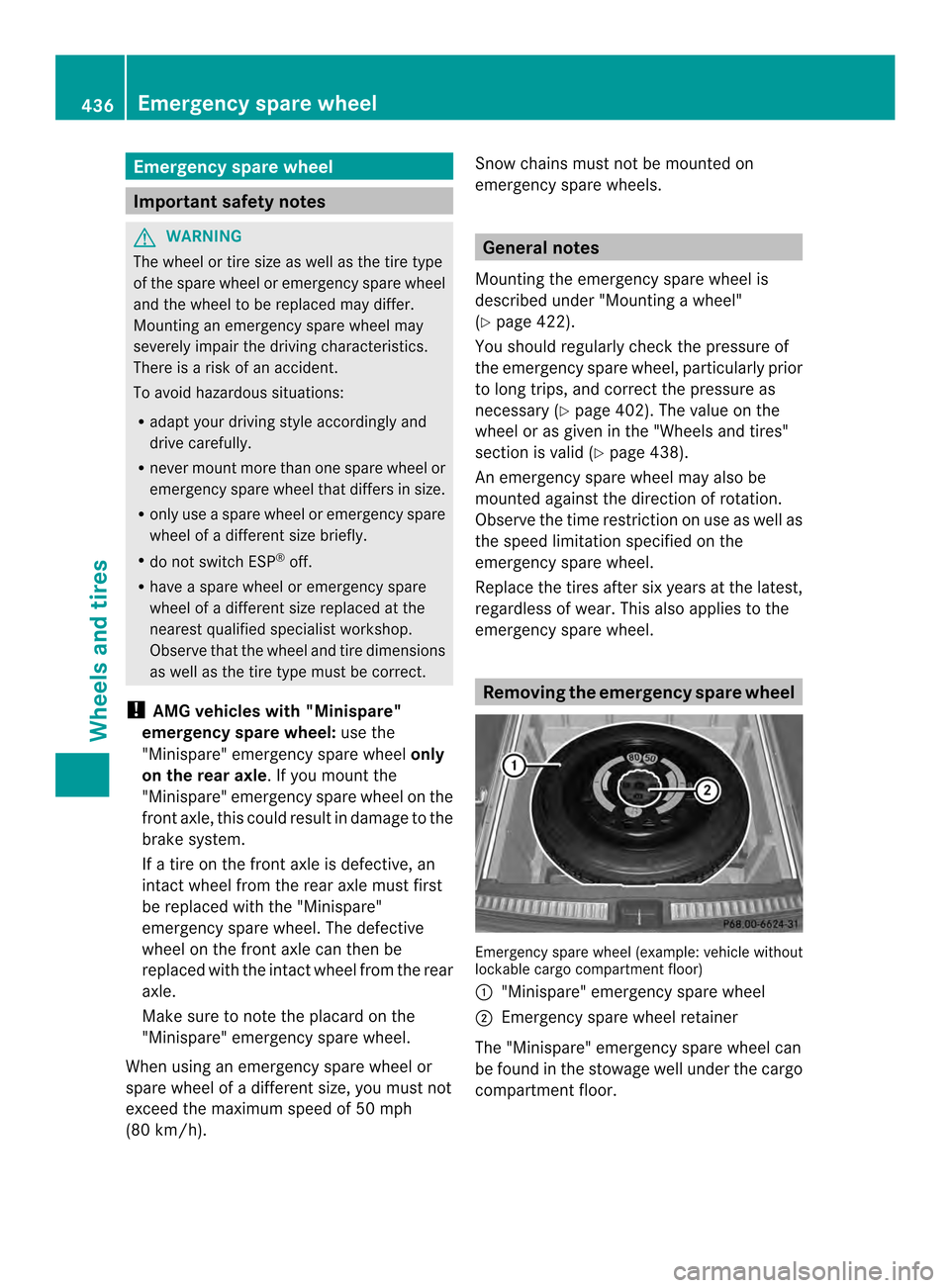
emergency spare wheel. Removing the emergency spare wheel
Emergency spare wheel (example: vehicle without
lockable cargo compartmen
tfloor)
0002 "Minispare" emergency spare wheel
0003 Emergency spare wheel retainer
The "Minispare" emergency spare wheel can
be found in the stowage well under the cargo
compartment floor. 436
Emergency spare wheelWheels and tires
Page 439 of 462
X
Lift the cargo compartment floor up
(Y page 342).
X Vehicles with trailer tow hitch: remove
the ball coupling stowage tray
(Y page 255).
X Vehicles without alockable cargo
compartment floor: turn emergency
spare wheel retainer 0003counter-clockwise
and remove it.
X Remove "Minispare" emergency spare
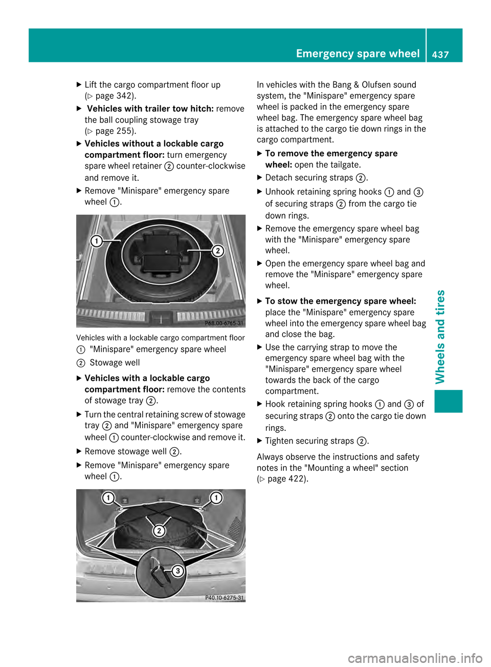
wheel 0002. Vehicles with a lockable cargo compartmen
tfloor
0002 "Minispare" emergency spare wheel
0003 Stowage well
X Vehicles with alockable cargo
compartment floor: remove the contents
of stowage tray 0003.
X Turn the central retaining screw of stowage
tray 0003and "Minispare" emergency spare
wheel 0002counter-clockwise and remove it.
X Remove stowage well 0003.
X Remove "Minispare" emergency spare
wheel 0002. In vehicles with the Ban
g&Olufsen sound
system, the "Minispare" emergency spare
wheel is packed in the emergency spare
wheel bag. The emergency spare wheel bag
is attached to the carg otie down rings in the
cargo compartment.
X To remove the emergency spare
wheel: open the tailgate.
X Detach securing straps 0003.
X Unhook retaining spring hooks 0002and 0023
of securing straps 0003from the cargo tie
down rings.
X Remove the emergency spare wheel bag
with the "Minispare" emergency spare
wheel.
X Open the emergency spare wheel bag and
remove the "Minispare" emergency spare
wheel.
X To stow the emergency spare wheel:
place the "Minispare" emergency spare
wheel into the emergency spare wheel bag
and close the bag.
X Use the carrying strap to move the
emergency spare wheel bag with the
"Minispare" emergency spare wheel
towards the back of the cargo
compartment.
X Hook retaining spring hooks 0002and 0023of
securing straps 0003onto the cargo tie down
rings.
X Tighten securing straps 0003.
Always observe the instructions and safety
notes in the "Mounting awheel" section
(Y page 422). Emergency spare wheel
437Wheels and tires Z
Page 453 of 462

Filling capacities
Model Capacity
ML 250 BlueTEC
4MATIC
Approx. 10.7 US qt
(10.1 l) ML 350
ML 350 4MATIC
Approx. 11.1 US qt
(10.5 l) ML 350 BlueTEC 4
MATIC
Approx. 12.2 US qt
(11.5 l) ML 550 4MATIC
Approx. 11.6 US qt
(11.0 l) ML 63 AMG
4MATIC
Approx. 12.5 US qt
(11.8 l) i
Use MB 325.0 or MB 326.0 corrosion
inhibitor/antifreeze. Windshield washer system
Important safety notes G
WARNING
Windshield washe rconcentrate is highly
flammable. If it comes into contact with hot
engine components or the exhaust system it
could ignite. There is a risk of fire and injury.
Make sure that no windshield washer
concentrate is spilled next to the filler neck.
! Do not add distilled or de-ionized water to
the washer fluid container. Otherwise, the
level sensor may be damaged.
! Only MB SummerFit and MB WinterFit
washer fluid should be mixed together. The
spray nozzles may otherwise become
blocked.
When handling washer fluid, observe the
important safety notes on service products
(Y page 444). At temperatures above freezing:
X
Fill the washer fluid reservoir with a mixture
of water and windshield washer fluid, e.g.
MB SummerFit.
Add 1 part MB SummerFit to 100 parts water.
At temperatures below freezing:
X Fill the washer fluid reservoir with a mixture
of water and washer fluid, e.g. MB
WinterFit.
Adapt the mixing ratio to the outside
temperature.
R Down to 14 ‡ (001910 †): mix 1 part MB
WinterFit to 2 parts water.
R Down to 00194 ‡ (001920 †): mix 1 part MB
WinterFit to 1 part water.
R Down to 001920.2 ‡ (001929 †): mix 2 parts MB
WinterFit to 1 part water.
i Add windshield washer fluid, e.g. MB
SummerFit or MB WinterFit, to the washer
fluid all year round. Climate control system refrigerant
Important safety notes The climate control system of your vehicle is
filled with refrigerant R-134a.
The instruction label regarding the refrigerant
type used can be found on the radiator cross
member.
!
Only the refrigerant R-134a and the PAG
oil approved by Mercedes-Benz may be
used. The approved PAG oil may not be
mixed with any other PAG oil that is not
approved for R-134a refrigerant.
Otherwise, the climate control system may
be damaged.
Service work, such as topping-up refrigerant
or replacing components, may only be carried
out by a qualified specialist workshop. All
applicable regulations must be adhered to,
SAE standard J639 included. Service products and filling capacities
451Technical data Z