2014 MERCEDES-BENZ M-Class rear view mirror
[x] Cancel search: rear view mirrorPage 222 of 462

Once you have exited the parking space
completely, the steering wheel is moved to
the straight-ahead position. You hear a tone
and the
Park Assist Switched Off message appears in the multifunction
display. You will then have to steer and merge
into traffic on your own. PARKTRONIC is still
available. You can take over the steering,
before the vehicle has exited the parking
space completely. This is useful, for example
when you recognize that it is already possible
to pull out of the parking space.
Canceling Active Parking Assist
X
Stop the movement of the multifunction
steering wheel or steer yourself.
Active Parking Assist will be canceled at
once. The Park Assist Canceled message appears in the multifunction
display.
or
X Press the PARKTRONIC button on the
center console (Y page 215).
PARKTRONIC is switched off and Active
Parking Assist is immediately canceled.
The Park Assist Canceled message
appears in the multifunction display.
Active Parking Assist is canceled
automatically if:
R the electric parking brake is engaged
R transmission position Pis selected
R parking using Active Parking Assist is no
longer possible
R you are driving faster than 6 mph
(10 km/h)
R a wheel spins, ESP ®
intervenes or fails. The
000F warning lamp lights up in the
instrument cluster.
Aw arning tone sounds. The parking symbol
disappears and the multifunction display
shows the Park Assist Canceled message.
If Active Parking Assist is canceled, you must
steer again yourself. Towing
atrailer For vehicles with a trailer tow hitch, the
minimum length for parking spaces is slightly
increased.
If you have attached a trailer to your vehicle,
you should not use Active Parking Assist.
Once the electrical connectio
nis established
between your vehicle and the trailer, Active
Parking Assist is no longer available.
PARKTRONIC is deactivated for the rear area. Rear view camera
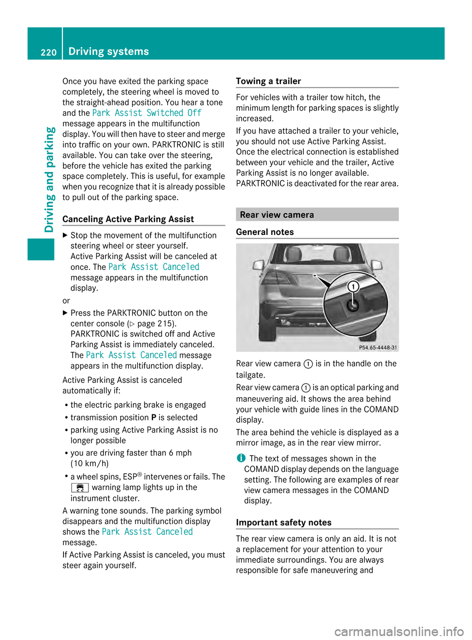
General notes Rear view camera
0002is in the handle on the
tailgate.
Rear view camera 0002is an optical parking and
maneuvering aid. It shows the area behind
your vehicle with guide lines in the COMAND
display.
The area behind the vehicle is displayed as a
mirror image, as in the rear view mirror.
i The text of messages shown in the
COMAND display depends on the language
setting. The following are examples of rear
view camera messages in the COMAND
display.
Important safety notes The rear view camera is only an aid. It is not
a replacement for your attention to your
immediate surroundings. You are always
responsible for safe maneuvering and220
Driving systemsDriving and parking
Page 225 of 462

0023
Yellow guide line at a distance of
approximately 3 ft (1.0 m) from the rear
of the vehicle
0022 Red guide line at a distanc eof
approximately 10 in (0.25 m) from the
rear of the vehicle
X Make sure that the rear view camera is
switched on (Y page 221).
The lane and the guide lines are shown.
X With the help of white guide line 0002, check
whether the vehicle will fit into the parking
space.
X Using white guide line 0002as a guide,
carefully back up until you reach the end
position.
Red guide line 0022is then at the end of the
parking space. The vehicle is almost
parallel in the parking space.
Reverse perpendicular parking with the
steering wheel at an angle Turning the steering wheel
0002
Red guide line for the vehicle width
including the exterior mirrors, for current
steering wheel angle (dynamic)
0003 Parking space marking
X Make sure that the rear view camera is
switched on (Y page 221).
The lane and the guide lines are shown.
X Drive past the parking space and bring the
vehicle to a standstill.
X While the vehicle is at a standstill, tur nthe
steering wheel in the direction of the parking space until red guide line
0002
reaches parking space marking 0003.
X Keep the steering wheel in that position
and back up carefully. Backing up with the steering wheel turned
0002
Red guide line for the vehicle width
including the exterior mirrors, for current
steering wheel angle (dynamic)
X Stop the vehicle when it is almost exactly
in front of the parking space.
The white lane should be as close to parallel
with the parking space marking as
possible. Driving to the final position
0002
White guide line at current steering wheel
angle
0003 Parking space marking
X Turn the steering wheel to the center
position while the vehicle is stationary. Driving systems
223Driving and parking Z
Page 227 of 462

X
Use the COMAND controller to select
symbol 0020, see the separate operating
instructions for COMAND.
The "Coupling up a trailer" function is
selected. The distance specifications now
only apply to objects that are at the same
level as the ball coupling.
X Back up carefully, making sure that trailer
drawbarm arker assistant 0023points
approximately in the direction of trailer
drawbar 0022.
X Reverse carefully until trailer drawbar 0022
reaches red guide line 0003.
X Couple up the trailer (Y page 253).360° camera (surround view)
General notes The 360° camera is a system consisting of
four cameras.
The system analyzes images from the
following cameras:
R Rear view camera
R Front camera
R Two cameras in the exterior rear view
mirrors
The cameras capture the immediate
surroundings of the vehicle .The system
supports you, e.g. when parking or if vision is
restricted at an exit.
The 360° camera images can be shown in full
screen mode or in seven different split-screen
views on the COMAND display. Asplit-screen
view also includes a top view of the vehicle.
This view is calculated from the data supplied
by the installed cameras (virtual camera).
The seven split-screen views are:
R top view and picture from the rear view
camera (130 °viewing angle)
R top view and picture fro mthe front camera
(without displaying the maximum steering
wheel angle)
R top view and enlarged rear view R
top view and enlarged front view
R top view and trailer view (vehicles with
trailer tow hitch)
R top view and pictures from the rearward
facing mirror cameras (rear wheel view)
R top view and pictures from the forward
facing mirror cameras (front wheel view)
i The top view and trailer view are available
for vehicles equipped with a trailer tow
hitch.
When the function is active and you shift the
transmission from position Dor Rto N, you
see the previous view in the COMAND
display. The dynamic guidelines are hidden.
When you change between transmission
positions Dand R, you see the previously
selected front or rear view.
Important safety notes The 360° camera is only an aid. It is not a
replacement for your attention to your
immediate surroundings. You are always
responsible for safe maneuvering and
parking. When maneuvering or parking, make
sure that there are no persons, animals or
objects in the area in which you are
maneuvering.
The 360° camera may show a distorted view
of obstacles, show them incorrectly or not at
all. It cannot show objects in the following
areas:
R
under the front bumper
R very close to the front bumper
R very close to the rear bumper
R under the rear bumper
R in close range above the handle on the
trunk lid
R very close to the exterior mirrors
You are always responsible for safety, and
must always pay attention to your
surroundings when parking and
maneuvering. This applies to the areas
behind, in front of and beside the vehicle. You Driving systems
225Driving and parking Z
Page 228 of 462

could otherwise endanger yoursel
fand
others.
The 360° camera will not function or will
function in a limited manner:
R if the doors are open
R if the exterio rmirrors are folded in
R if the trunk lid is open
R in heavy rain, snow or fog
R at night or in very dark places
R if the cameras are exposed to very bright
light
R if the area is lit by fluorescen tlight or LED
lighting (the display may flicker)
R if you exit a heated garage in winter,
resulting in a rapid change in temperature
R if the camera lenses are dirty or covered
R if the vehicle components in which the
cameras are installed are damaged. In this
event, have the camera position and setting
checked at a qualified specialist workshop.
Do not use the 360 °camera in this case. You
can otherwise injure other sorcause damage
to objects or the vehicle.
Activation conditions The 360° camera image can be displayed if:
R
your vehicle is equipped with a 360°
camera
R COMAND is switched on, see the separate
COMAND operating instructions
R the 360° Camera function is activated
Activating the 360° camera using the
SYS button X
Press and hold the 0003button for longer
than 2seconds, see the separate COMAND
operating instructions.
Depending on whether position Dor Ris
engaged, the following is shown:
R full screen display with the image from
the front camera
R full screen display with the image from
the rear camera Activating the 360° camer
awith
COMAND X
Press the 0003button, see the separate
COMAN Doperating instructions.
X Select System by turning
000E0002000Fthe
COMAND controller and press 000Cto
confirm.
X Select 360° Camera and press
000Cto
confirm.
Depending on whether position Dor Ris
engaged, the following is shown:
R a split scree nwith top view and the
image from the front camera or
R a split screen with top view and the
image from the rear view camera
For further information about the COMAND
controller, see the separat eCOMAND
operating instructions.
Activating the 360° camera using
reverse gear The 360° camera images can be
automatically displayed by engaging reverse
gear.
X
Make sure that the SmartKey is in position
2in the ignition lock.
X Make sure that the Activation by R gear setting is active in COMAND, see the
separate COMAND operating instructions.
X To show the 360° camera image: engage
reverse gear.
The COMAND display shows the area
behind the vehicle in split screen:
R vehicle with guide lines
R top view of the vehicle
Selecting the split-screen and full
screen displays X
To switch between split screen views:
switch to the line with the vehicle icons by
sliding 000B0002the COMAND controller.
X Turn 000E0002000F the COMAND controller and
select one of the vehicle symbols. 226
Driving systemsDriving and parking
Page 229 of 462

X
To switc hto full screen mode: select
Full Screen by turning
000E0002000Fthe
COMAND controller and press 000Cto
confirm.
Displays in the COMAND display Important safety notes
!
Objects not at ground level may appear to
be further away than they actually are, e.g.:
R the bumper of a parked vehicle
R the drawbar of a trailer
R the ball coupling of a trailer tow hitch
R the rear section of an HGV
R a slanted post
Use the guidelines only for orientation.
Approach objects no further than the
bottom-mos tguideline.
Top view with picture from the rear view
camera 0002
Symbol for the split scree nsetting with
top view and rear view camera image
0003 Yellow guide line at a distance of
approximately 13 ft (4.0 m) from the rear
of the vehicle
0023 Yellow guide line for the vehicle width
including the exterior mirrors, for current
steering wheel angle (dynamic)
0022 Yellow lane marking tires at current
steering wheel angle (dynamic) 0020
Yellow guide line at a distance of
approximately 3 ft (1.0 m) from the rear
of the vehicle
0021 Vehicle center axle (marker assistance)
0014 Red guide line at a distance of
approximately 12 in (0.30 m) from the
rear of the vehicle
0015 Bumper
The guide lines are show nwhen the
transmission is in position R.
The distance specifications only apply to
objects that are at ground level.
Top view with picture from the front
camera 0002
Symbol for the split screen setting with
top view and front camera image
0003 Yellow guide line at a distance of
approximately 13 ft (4.0 m) from the front
of the vehicle
0023 Yellow guide line for the vehicle width
including the exterior mirrors, for current
steering wheel angle (dynamic)
0022 Yellow lane marking tires at current
steering wheel angle (dynamic) Driving systems
227Driving and parking Z
Page 230 of 462

0020
Yellow guide line at a distance of
approximately 3 ft (1.0 m) from the front
of the vehicle
0021 Red guide line at a distanc eof
approximately 12 in (0.30 m) from the
front of the vehicle
Top view and enlarged rea rview 0002
Symbol for the split screen setting with
top view and rear view camera image
enlarged
0003 Red guide line at a distance of
approximately 12 in (0.30 m) from the
rear of the vehicle
This view assists you in estimating the
distance to the vehicle behind you.
i This setting can also be selected as an
enlarged fron tview. Top view with picture from the mirror
camera 0002
Symbol for the top view and forward-
facing mirror camera setting
0003 Yellow guide line for the vehicle width
including the exterior mirrors (right side
of vehicle)
0023 Yellow guide line for the vehicle width
including the exterior mirrors (left side of
vehicle)
Top view with trailer view 0002
Symbol for the trailer view setting
0003 Trailer drawbar marker assistant
0023 Red guide line at a distanc eof
approximately 12 in (0.30 m)from the ball
coupling 228
Driving systemsDriving and parking
Page 235 of 462

Problems with Night View Assist Plus
Problem Possible causes/consequences and
0001 Solutions
The picture quality of
Night View Assist Plus
has deteriorated. The windshield wipers are smearing the windshield.
X
Replace the wiper blades (Y page 133). The windshield is smeared after the vehicle has been cleaned in a
car wash.
X
Cleant he windshield (Y page 373). There is windshield chip damage in the camera's field of vision.
X
Replace the windshield. The windshield is fogged up on the inside.
X
Defrost the windshield (Y page 150). The windshield is iced up.
X
De-ice the windshield (Y page 149). There is dirt on the inside of the windshield.
X
Cleant he inside of the windshield (Y page 373).Lane Tracking package
General notes The Lane Tracking package consists of Blind
Spot Assist (Y page 233) and Lane Keeping
Assist (Y page 235).
Blind Spot Assist General notes
Blind Spot Assist uses a radar sensor system
to monitor the areas on both sides of your
vehicle. It supports you from a speed of
approximately 20 mph (30 km/h). A warning
display in the exterio rmirrors draws your
attention to vehicles detected in the
monitored area. If you then switch on the
corresponding tur nsignal to change lanes,
you will also receive a visual and audible
collision warning. Blind Spot Assist uses
sensors in the rear bumper for monitoring
purposes. For Blind Spot Assist to assist you when
driving, the radar sensor system must be:
R
activated(Y page 276)
R operational
Important safety notes G
WARNING
Blind Spot Assist does not react to:
R vehicles overtaken too closely on the side,
placing the minthe blind spot area
R vehicles which approach with a large speed
differential and overtake your vehicle
As a result, Blind Spot Assist may not give
warnings in such situations. There is a risk of
an accident.
Always observe the traffic conditions
carefully, and maintain a safe lateral distance.
Blind Spot Assist is only an aid. It may fail to
detect some vehicles and is no substitute for
attentive driving.
i USA only: Driving systems
233Driving and parking Z
Page 259 of 462

of the towing vehicle, as the latter is
equipped with an anti-lock brake system.
Doing so will result in a loss of function of
the brake systems of both the vehicle and
the trailer.
X Make sure that the automatic transmission
is set to position P.
X Apply the vehicle's electric parking brake.
X Start the engine.
X Vehicles with the AIRMATIC package:
select highway level.
X Vehicles with ADS: set ADS toAUTOor
COMF.
X Switch off the engine.
X Close all doors and the tailgate.
X Couple up the trailer.
X Establish all electrical connections.
X Check that the trailer lighting system is
working.
i Vehicles with the AIRMATIC package:
with a trailer attached, the vehicle will
always remain at highway level. When
coupling up a trailer, please observe the
following:
R Unless highway level has been set
manually, the vehicle is automatically
lowered to highway level. This is the case
if a speed of 5mph(8km/h) is reached.
R High-speed level is not available.
These restrictions apply to all accessories
powered through a connectio nto the trailer
power socket of your vehicle, e.g. a bicycle
carrier.
Observe the maximum permissible trailer
dimensions (width and length).
Most U.S. states and all Canadia nprovinces
require by law:
R Safety chains between the towing vehicle
and the trailer. The chains should be cross-
wound under the trailer drawbar. They must
be fastened to the vehicle's trailer
coupling, not to the bumper or the axle. Leave enough play in the chains to make
tight cornering possible.
R As eparate brake system for certain types
of trailer.
R As afety switch for braked trailers. Check
the specific legal requirements applicable
to your state.
If the trailer detaches from the towing
vehicle, the safety switch applies the
trailer's brakes. Towing
atrailer
There are numerous legal requirements
concerning the towing of a trailer, e.g .speed
restrictions. Make sure that your vehicle/
trailer combination complies with the local
requirements not only in your area of
residence but also at any location to which
you are traveling. The police and local
authorities can provide reliable information.
Please observe the following when towing a
trailer:
R In order to accumulate driving experience
and accustom yourself to the new handling
characteristics, practice the following at a
location where there is no traffic:
-Cornering
- Stopping
- Backing up
R Before driving, check:
-the trailer tow hitch
- the safety switch for braked trailers
- the safety chains
- electrical connections
- the lights
- the wheels
R Adjust the exterior mirrors to provide an
unobstructed view of the rear section of the
trailer.
R If the trailer has electronically controlled
brakes, pull away carefully. Brake manually
using the brake controller and check
whether the brakes function correctly. Towing
atrailer
257Driving an d parking Z