Page 426 of 462

R
before raising the vehicle, secure it from
rolling away by applying the parking brake
and inserting wheel chocks. Never
disengage the parking brake while the
vehicle is raised.
R the jack must be placed on a firm, flat and
non-slip surface. On a loose surface, a
large, load-bearing underlay must be used.
On a slippery surface, a non-slip underlay
must be used, e.g. rubber mats.
R do not use wooden blocks or similar
objects as a jack underlay. Otherwise, the
jack will not be able to achieve its load-
bearing capacity due to the restricted
height.
R make sure that the distance between the
underside of the tires and the ground does
not exceed 1.2 in (3 cm).
R never place your hands and feet under the
raised vehicle.
R never lie under the raised vehicle.
R never start the engine when the vehicle is
raised.
R never open or close a door or the tailgate
when the vehicle is raised.
R make sure that no person sare present in
the vehicle when the vehicl eis raised. X
Using lug wrench 0002, loosen the bolts on
the wheel you wish to change by abouto ne
full turn. Do not unscrew the bolts
completely. The jacking points are located jus
tbehind the
front wheel housings and just in front of the
rear wheel housings (arrows).
X Take the ratchet wrench out of the vehicle
tool kit and place it on the hexagon nut of
the jack so that the letters AUFare visible. 0003
Jacking points
0023 Jack
0022 Crank
X Position jack 0023at jacking point 0003.
The alignment bolt on the jack must be
inserted into the intended jacking point
hole. 424
Changing
awheelWheels and tires
Page 427 of 462

Example
X
Make sure the foot of the jack is directly
beneath the jacking point.
X Turn ratchet wrench 0022until jack 0023sits
completely on jacking point 0003and the
base of the jack lies evenly on the ground.
X Turn ratchet wrench 0022until the tire is
raised amaximum of 1.2 in (3 cm )from the
ground.
Removing awheel !
Do not place wheel bolts in sand or on a
dirty surface. The bol tand wheel hub
threads could otherwise be damaged when
you screw them in. X
Unscrew the uppermost wheel bolt
completely.
X Screw alignment bolt 0002into the thread
instead of the wheel bolt.
X Unscrew the remaining whee lbolts fully.
X Remove the wheel. Mounting
anew wheel G
WARNING
Oiled or greased wheel bolts or damaged
wheel bolts/hub threads can cause the wheel
bolts to come loose .As a result, you could
lose a wheel while driving. There is a risk of
accident.
Never oil or grease wheel bolts. In the event
of damage to the threads, contact a qualified
specialist workshop immediately.H ave the
damaged wheel bolts or hub threads
replaced/renewed. Do no tcontinue driving. G
WARNING
If you tighten the wheel bolts or wheel nuts
when the vehicle is raised, the jack could tip
over. There is a risk of injury.
Only tighten the wheel bolts or wheel nuts
when the vehicle is on the ground.
! To prevent damage to the paintwork, hold
the wheel securely against the wheel hub
while screwing in the first wheel bolt.
Always pay attention to the instructions and
safety notes in the "Changing a wheel"
section (Y page 421).
Only use wheel bolts that have been designed
for the wheel and the vehicle. For safety
reasons, Mercedes-Benz recommends that
you only use wheel bolts which have been
approved for Mercedes-Benz vehicles and the
respective wheel.
! Always use wheel bolts 0003to mount the
"Minispare" emergency spare wheel. Using
other wheel bolts to mount the "Minispare"
emergency spare wheel could damage the
brake system. Changing
awheel
425Wheels and tires Z
Page 439 of 462

X
Lift the cargo compartment floor up
(Y page 342).
X Vehicles with trailer tow hitch: remove
the ball coupling stowage tray
(Y page 255).
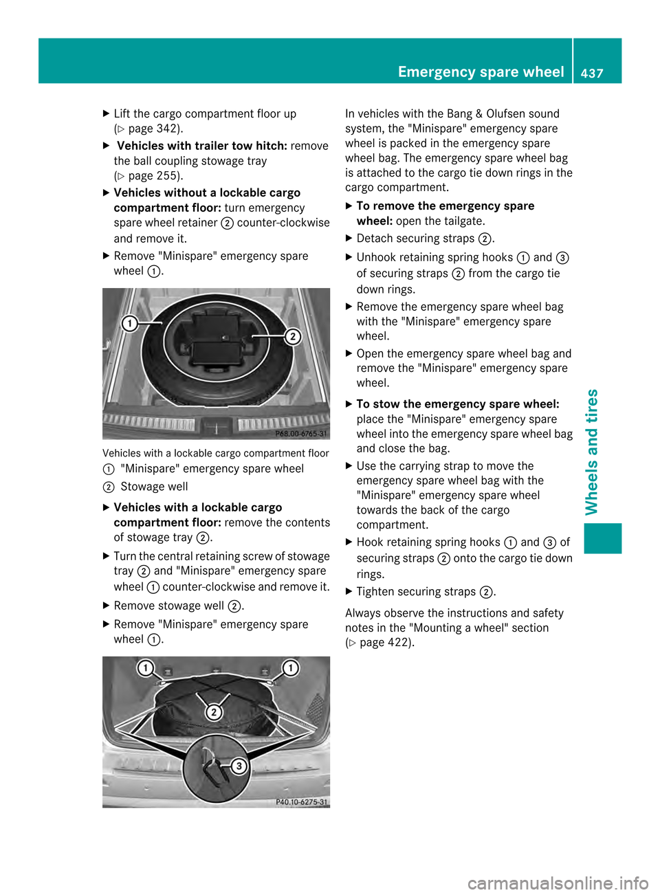
X Vehicles without alockable cargo
compartment floor: turn emergency
spare wheel retainer 0003counter-clockwise
and remove it.
X Remove "Minispare" emergency spare
wheel 0002. Vehicles with a lockable cargo compartmen
tfloor
0002 "Minispare" emergency spare wheel
0003 Stowage well
X Vehicles with alockable cargo
compartment floor: remove the contents
of stowage tray 0003.
X Turn the central retaining screw of stowage
tray 0003and "Minispare" emergency spare
wheel 0002counter-clockwise and remove it.
X Remove stowage well 0003.
X Remove "Minispare" emergency spare
wheel 0002. In vehicles with the Ban
g&Olufsen sound
system, the "Minispare" emergency spare
wheel is packed in the emergency spare
wheel bag. The emergency spare wheel bag
is attached to the carg otie down rings in the
cargo compartment.
X To remove the emergency spare
wheel: open the tailgate.
X Detach securing straps 0003.
X Unhook retaining spring hooks 0002and 0023
of securing straps 0003from the cargo tie
down rings.
X Remove the emergency spare wheel bag
with the "Minispare" emergency spare
wheel.
X Open the emergency spare wheel bag and
remove the "Minispare" emergency spare
wheel.
X To stow the emergency spare wheel:
place the "Minispare" emergency spare
wheel into the emergency spare wheel bag
and close the bag.
X Use the carrying strap to move the
emergency spare wheel bag with the
"Minispare" emergency spare wheel
towards the back of the cargo
compartment.
X Hook retaining spring hooks 0002and 0023of
securing straps 0003onto the cargo tie down
rings.
X Tighten securing straps 0003.
Always observe the instructions and safety
notes in the "Mounting awheel" section
(Y page 422). Emergency spare wheel
437Wheels and tires Z