2014 MERCEDES-BENZ CLS SHOOTING BRAKE rear view mirror
[x] Cancel search: rear view mirrorPage 112 of 417
X
Pull or push the bottom of the head
restraint until it has reached the desired
position.
i The tilt angle can only be adjusted on the
two outer head restraints. The centre head restraint is only height-adjustable.
Removing and fitting the rear seat head
restraints G
WARNING
The head restraints cannot provide the inten-
ded protection unless they are fitted and
adjusted correctly. There is an increased risk of injury to the head and neck in the event of
an accident or sudden braking, for example.
Always drive with the head restraints fitted.
Ensure that the centre of the head restraints
support the back of each vehicle occupant's
head at eye level before driving off.
! Make sure that the rear window roller
sunblind is retracted when removing the
rear head restraints. Otherwise, you could
damage the roller sunblind. CLS Coupé
i
The head restraints can only be removed
if the rear seat folds forward.
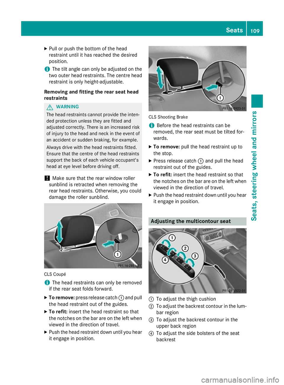
X To remove: press release catch :and pull
the head restraint out of the guides.
X To refit: insert the head restraint so that
the notches on the bar are on the left when
viewed in the direction of travel.
X Push the head restraint down until you hear
it engage in position. CLS Shooting Brake
i
Before the head restraints can be
removed, the rear seat must be tilted for-
wards.
X To remove: pull the head restraint up to
the stop.
X Press release catch :and pull the head
restraint out of the guides.
X To refit: insert the head restraint so that
the notches on the bar are on the left when viewed in the direction of travel.
X Push the head restraint down until you hear
it engage in position. Adjusting the multicontour seat
:
To adjust the thigh cushion
; To adjust the backrest contour in the lum-
bar region
= To adjust the backrest contour in the
upper back region
? To adjust the side bolsters of the seat
backrest Seats
109Seats, steering wheel and mirrors Z
Page 119 of 417
when you store the setting with the memory
function (Y page 119).
Crash-responsive EASY-EXIT feature If the crash-responsive EASY-EXIT feature is
triggered in an accident, the steering column
will move upwards when the driver's door is
opened. This occurs irrespective of the posi-
tion of the key in the ignition lock. This makes it easier to exit the vehicle and rescue the
occupants.
The crash-responsive EASY-EXIT feature is
only operational if the EASY-EXIT/ENTRY fea-
ture is activated in the on-board computer
(Y page 257). Mirrors
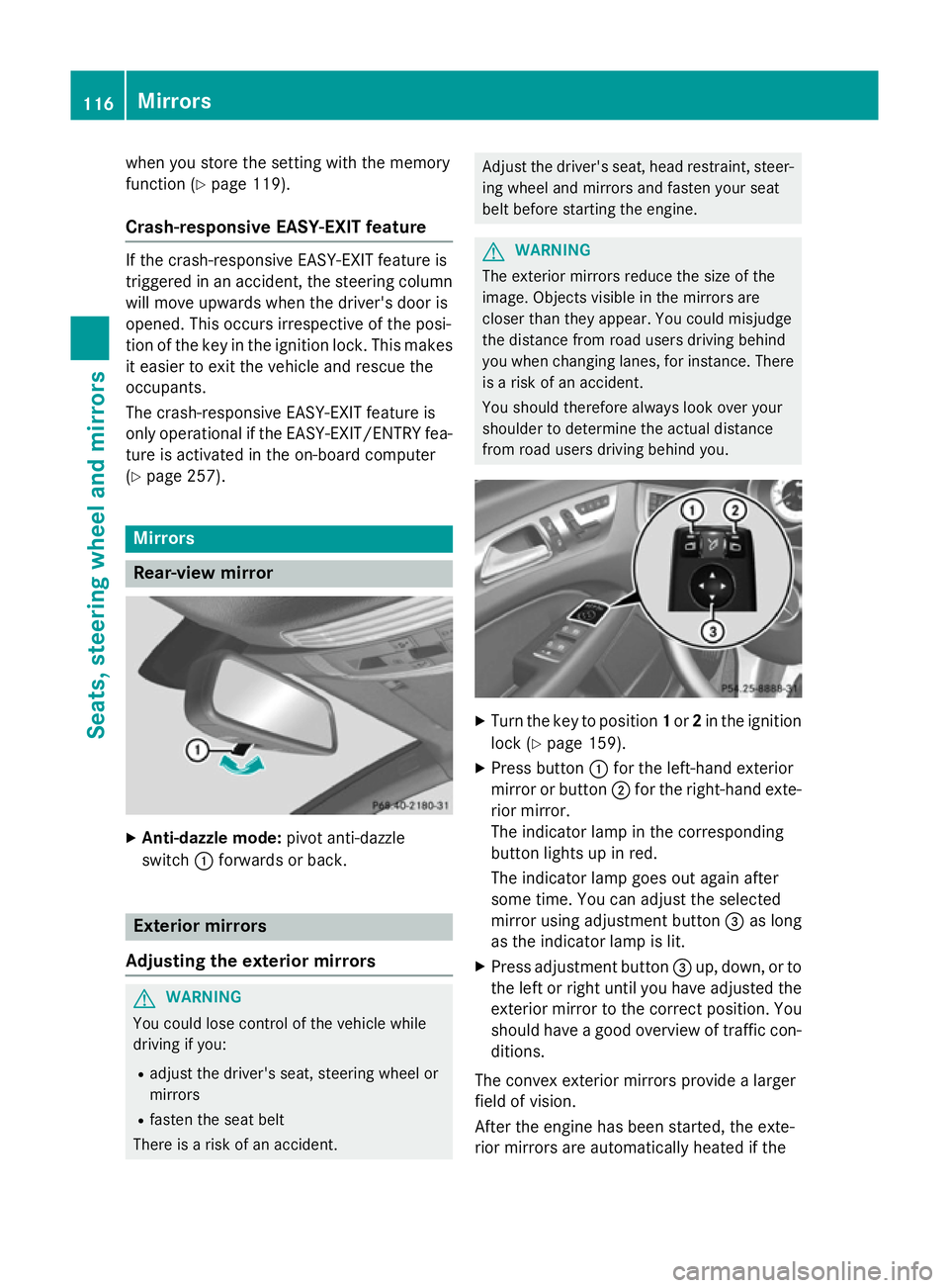
Rear-view mirror
X
Anti-dazzle mode: pivot anti-dazzle
switch :forwards or back. Exterior mirrors
Adjusting the exterior mirrors G
WARNING
You could lose control of the vehicle while
driving if you:
R adjust the driver's seat, steering wheel or
mirrors
R fasten the seat belt
There is a risk of an accident. Adjust the driver's seat, head restraint, steer-
ing wheel and mirrors and fasten your seat
belt before starting the engine. G
WARNING
The exterior mirrors reduce the size of the
image. Objects visible in the mirrors are
closer than they appear. You could misjudge
the distance from road users driving behind
you when changing lanes, for instance. There is a risk of an accident.
You should therefore always look over your
shoulder to determine the actual distance
from road users driving behind you. X
Turn the key to position 1or 2in the ignition
lock (Y page 159).
X Press button :for the left-hand exterior
mirror or button ;for the right-hand exte-
rior mirror.
The indicator lamp in the corresponding
button lights up in red.
The indicator lamp goes out again after
some time. You can adjust the selected
mirror using adjustment button =as long
as the indicator lamp is lit.
X Press adjustment button =up, down, or to
the left or right until you have adjusted the
exterior mirror to the correct position. You
should have a good overview of traffic con- ditions.
The convex exterior mirrors provide a larger
field of vision.
After the engine has been started, the exte-
rior mirrors are automatically heated if the 116
MirrorsSeats, steering wheel and mirrors
Page 120 of 417
rear window heating is switched on and the
outside temperature is low. Heating takes a
maximum of ten minutes.
i The exterior mirrors can also be heated
manually by switching on the rear window
heating.
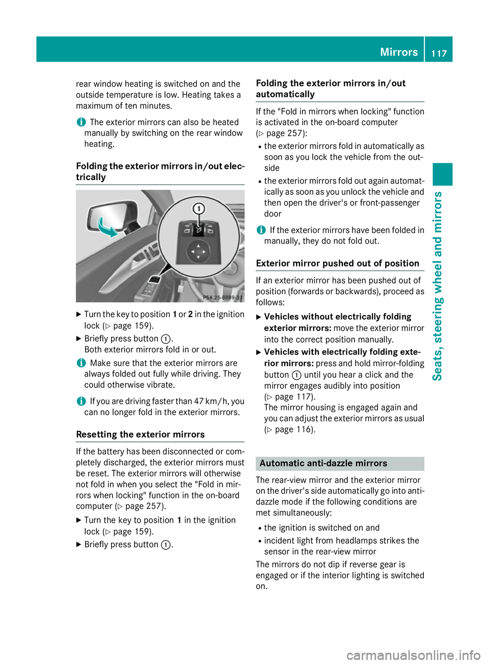
Folding the exterior mirrors in/out elec- trically X
Turn the key to position 1or 2in the ignition
lock (Y page 159).
X Briefly press button :.
Both exterior mirrors fold in or out.
i Make sure that the exterior mirrors are
always folded out fully while driving. They
could otherwise vibrate.
i If you are driving faster than 47 km/h, you
can no longer fold in the exterior mirrors.
Resetting the exterior mirrors If the battery has been disconnected or com-
pletely discharged, the exterior mirrors must
be reset. The exterior mirrors will otherwise
not fold in when you select the "Fold in mir-
rors when locking" function in the on-board
computer (Y page 257).
X Turn the key to position 1in the ignition
lock (Y page 159).
X Briefly press button :. Folding the exterior mirrors in/out
automatically If the "Fold in mirrors when locking" function
is activated in the on-board computer
(Y page 257):
R the exterior mirrors fold in automatically as
soon as you lock the vehicle from the out-
side
R the exterior mirrors fold out again automat-
ically as soon as you unlock the vehicle and
then open the driver's or front-passenger
door
i If the exterior mirrors have been folded in
manually, they do not fold out.
Exterior mirror pushed out of position If an exterior mirror has been pushed out of
position (forwards or backwards), proceed as
follows:
X Vehicles without electrically folding
exterior mirrors: move the exterior mirror
into the correct position manually.
X Vehicles with electrically folding exte-
rior mirrors: press and hold mirror-folding
button :until you hear a click and the
mirror engages audibly into position
(Y page 117).
The mirror housing is engaged again and
you can adjust the exterior mirrors as usual
(Y page 116). Automatic anti-dazzle mirrors
The rear-view mirror and the exterior mirror
on the driver's side automatically go into anti- dazzle mode if the following conditions are
met simultaneously:
R the ignition is switched on and
R incident light from headlamps strikes the
sensor in the rear-view mirror
The mirrors do not dip if reverse gear is
engaged or if the interior lighting is switched
on. Mirrors
117Seats, steering wheel and mirrors Z
Page 217 of 417
Reversing camera
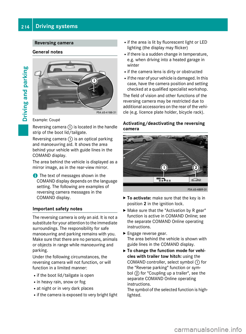
General notes Example: Coupé
Reversing camera :is located in the handle
strip of the boot lid/tailgate.
Reversing camera :is an optical parking
and manoeuvring aid. It shows the area
behind your vehicle with guide lines in the
COMAND display.
The area behind the vehicle is displayed as a
mirror image, as in the rear-view mirror.
i The text of messages shown in the
COMAND display depends on the language setting. The following are examples of
reversing camera messages in the
COMAND display.
Important safety notes The reversing camera is only an aid. It is not a
substitute for your attention to the immediate
surroundings. The responsibility for safe
manoeuvring and parking remains with you.
Make sure that there are no persons, animals
or objects in range while manoeuvring and
parking.
Under the following circumstances, the
reversing camera will not function, or will
function in a limited manner:
R if the boot lid/tailgate is open
R in heavy rain, snow or fog
R at night or in very dark places
R if the camera is exposed to very bright light R
if the area is lit by fluorescent light or LED
lighting (the display may flicker)
R if there is a sudden change in temperature,
e.g. when driving into a heated garage in
winter
R if the camera lens is dirty or obstructed
R if the rear of your vehicle is damaged. In this
case, have the camera position and setting checked at a qualified specialist workshop.
The field of vision and other functions of the
reversing camera may be restricted due to
additional accessories on the rear of the vehi-
cle (e.g. licence plate holder, bicycle rack).
Activating/deactivating the reversing
camera X
To activate: make sure that the key is in
position 2in the ignition lock.
X Make sure that the "Activation by R gear"
function is active in COMAND Online; see
the separate COMAND Online operating
instructions.
X Engage reverse gear.
The area behind the vehicle is shown with
guide lines in the COMAND display.
X To change the function mode for vehi-
cles with trailer tow hitch: using the
COMAND controller, select symbol :for
the "Reverse parking" function or sym-
bol ;for "Coupling up a trailer", see the
separate COMAND Online operating
instructions.
The symbol of the selected function is high- lighted. 214
Driving systemsDriving and parking
Page 218 of 417
To deactivate:
the reversing camera deacti-
vates if you shift the transmission to Por after
driving forwards a short distance.
Displays in the COMAND display The reversing camera may show a distorted
view of obstacles or show them incorrectly or
not at all. Obstacles are not shown by the
reversing camera in the following locations:
R very close to the rear bumper
R under the rear bumper
R in the area immediately above the tailgate/
boot
i The following reversing camera messages
in the COMAND display correspond to the
display in the CLS Coupé. The details of the
display of the guide lines differ slightly for
the CLS Shooting Brake.
! Objects not at ground level may appear to
be further away than they actually are, e.g.:
R the bumper of a parked vehicle
R the drawbar of a trailer
R the ball coupling of a trailer tow hitch
R the rear section of an HGV
R a slanted post
Use the guidelines only for orientation.
Approach objects no further than the bot-
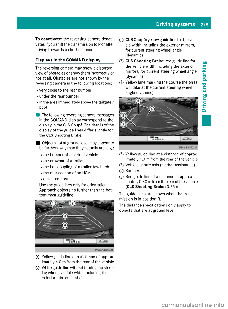
tom-most guideline. :
Yellow guide line at a distance of approx-
imately 4.0 mfrom the rear of the vehicle
; White guide line without turning the steer-
ing wheel, vehicle width including the
exterior mirrors (static) =
CLS Coupé: yellow guide line for the vehi-
cle width including the exterior mirrors,
for current steering wheel angle
(dynamic)
= CLS Shooting Brake: red guide line for
the vehicle width including the exterior
mirrors, for current steering wheel angle
(dynamic)
? Yellow lane marking the course the tyres
will take at the current steering wheel
angle (dynamic) A
Yellow guide line at a distance of approx-
imately 1.0 mfrom the rear of the vehicle
B Vehicle centre axis (marker assistance)
C Bumper
D Red guide line at a distance of approx-
imately 0.30 mfrom the rear of the vehicle
(CLS Shooting Brake: 0.25 m)
The guide lines are shown when the trans-
mission is in position R.
The distance specifications only apply to
objects that are at ground level. Driving systems
215Driving and parking Z
Page 226 of 417

Problems with Night View Assist Plus
Problem
Possible causes/consequences and
M
MSolutions The picture quality of
Night View Assist Plus
has deteriorated. The windscreen wipers are smearing the windscreen.
X Replace the wiper blades (Y page 134). The windscreen is smeared after the vehicle has been cleaned in a
car wash.
X Clean the windscreen (Y page 337). There is windscreen chip damage in the camera's field of vision.
X Replace the windscreen. The windscreen is misted up on the inside.
X Demist the windscreen (Y page 147). The windscreen is iced up.
X De-ice the windscreen (Y page 146). There is dirt on the inside of the windscreen.
X Clean the inside of the windscreen (Y page 337).Lane Tracking package
General notes The Lane Tracking package consists of Blind
Spot Assist (Y page 223) and Lane Keeping
Assist (Y page 225).
Blind Spot Assist General notes
Blind Spot Assist uses a radar sensor system
to monitor the areas on both sides of your
vehicle. It supports you from speeds of
30 km/h. A warning display in the exterior
mirrors draws your attention to vehicles
detected in the monitored area. If you then
switch on the corresponding turn signal to
change lane, you will also receive an optical
and audible collision warning. For monitoring,
Blind Spot Assist uses sensors in the rear
bumper. Important safety notes G
WARNING
Blind Spot Assist does not react to vehicles:
R overtaken too closely on the side, placing
them in the blind spot area
R when the difference in the speed of
approach and overtaking is too great
As a result, Blind Spot Assist cannot warn
drivers in these situations. There is a risk of an accident.
Always pay careful attention to the traffic sit- uation and maintain a safe distance at the side
of the vehicle.
Blind Spot Assist is only an aid. It may fail to
detect some vehicles and is no substitute for
attentive driving. Always ensure that there is
sufficient distance to the side for other road
users and obstacles. Driving systems
223Driving and parking Z
Page 317 of 417
Example: CLS Coupé
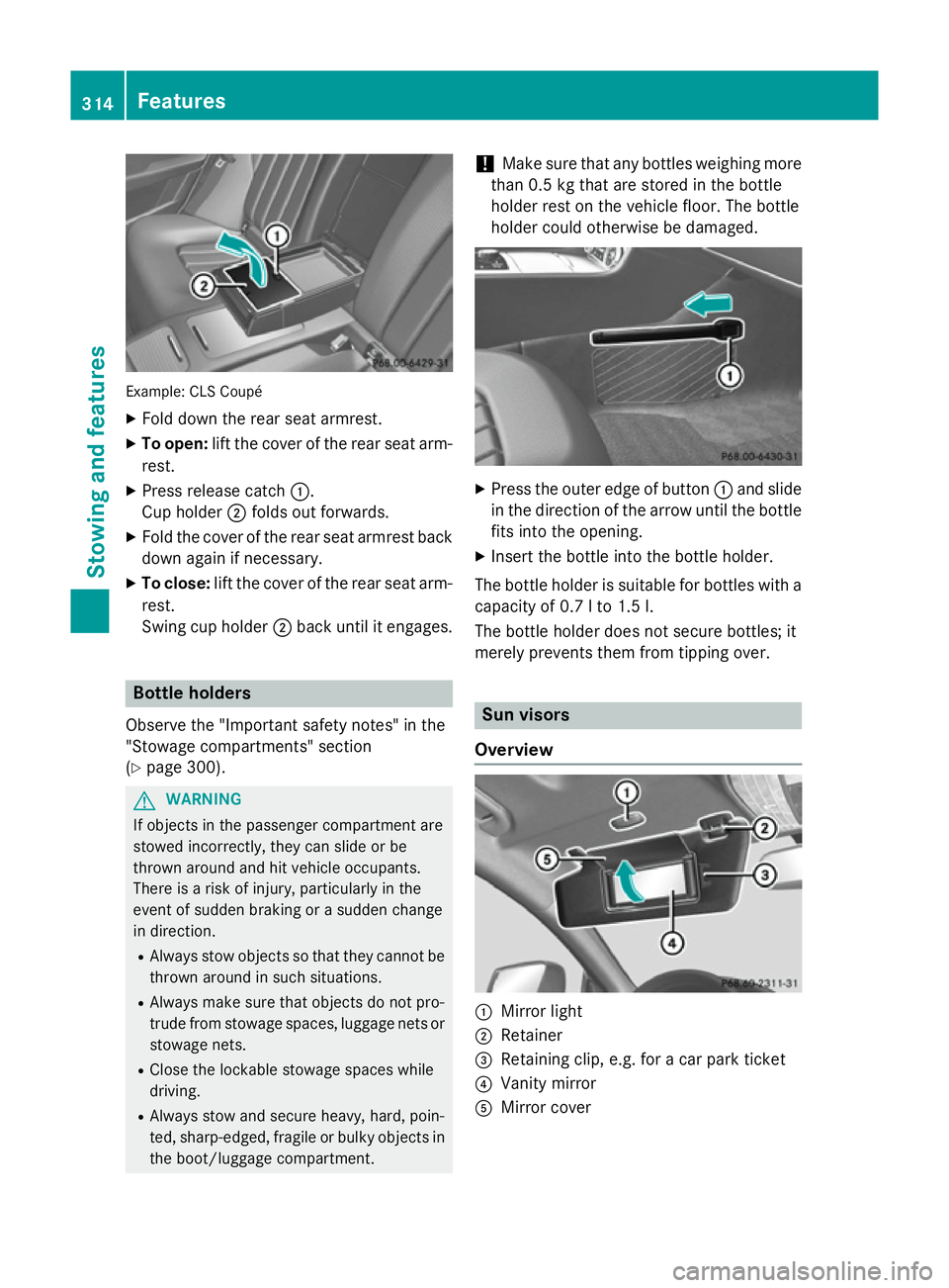
X Fold down the rear seat armrest.
X To open: lift the cover of the rear seat arm-
rest.
X Press release catch :.
Cup holder ;folds out forwards.
X Fold the cover of the rear seat armrest back
down again if necessary.
X To close: lift the cover of the rear seat arm-
rest.
Swing cup holder ;back until it engages. Bottle holders
Observe the "Important safety notes" in the
"Stowage compartments" section
(Y page 300). G
WARNING
If objects in the passenger compartment are
stowed incorrectly, they can slide or be
thrown around and hit vehicle occupants.
There is a risk of injury, particularly in the
event of sudden braking or a sudden change
in direction.
R Always stow objects so that they cannot be
thrown around in such situations.
R Always make sure that objects do not pro-
trude from stowage spaces, luggage nets or stowage nets.
R Close the lockable stowage spaces while
driving.
R Always stow and secure heavy, hard, poin-
ted, sharp-edged, fragile or bulky objects in
the boot/luggage compartment. !
Make sure that any bottles weighing more
than 0.5 kg that are stored in the bottle
holder rest on the vehicle floor. The bottle
holder could otherwise be damaged. X
Press the outer edge of button :and slide
in the direction of the arrow until the bottle
fits into the opening.
X Insert the bottle into the bottle holder.
The bottle holder is suitable for bottles with a
capacity of 0.7 lto 1.5 l.
The bottle holder does not secure bottles; it
merely prevents them from tipping over. Sun visors
Overview :
Mirror light
; Retainer
= Retaining clip, e.g. for a car park ticket
? Vanity mirror
A Mirror cover 314
FeaturesStowing and features
Page 323 of 417
Using a mobile phone
If the mobile phone is inserted in the mobile
phone bracket, the mobile phone will be
charged and connected with the exterior aer- ial.
X Open the telephone compartment
(Y page 302).
X Insert the mobile phone into the mobile
phone bracket; see the separate installa-
tion instructions for the mobile phone fit-
ting.
Operating the mobile phone You can operate the telephone using the
6 and~ buttons on the multifunction
steering wheel. You can operate other mobile
phone functions via the on-board computer
(Y page 247).
When you remove the key from the ignition
lock, the mobile phone is disconnected from
the hands-free system. Active calls will first
be transferred to the mobile phone directly. Garage door opener
General notes The HomeLink
®
garage door opener integra-
ted in the rear-view mirror allows you to oper-
ate up to three different door and gate sys-
tems.
Once programmed, the integrated garage
door opener in the rear-view mirror will
assume the function of the garage door sys-
tem's remote control. Please also read the
operating instructions for the garage door
system.
When programming a garage door opener,
park the vehicle outside the garage. Do not
run the engine while programming.
The garage door opener is only available for
certain countries. Observe the legal require-
ments for each individual country.
The HomeLink ®
garage door opener is com-
patible with most European garage and gate opener drives. More information on Home-
Link
®
and/or compatible products is availa-
ble:
R at a qualified specialised workshop
R via the HomeLink ®
Hotline
(0) 08000 466 354 65 or alternatively
+49 (0) 6838 907-277
R on the Internet at
http://www.homelink.com
Important safety notes G
WARNING
When you operate or program the garage door with the integrated garage door opener, per-
sons in the range of movement of the garage
door can become trapped or struck by the
garage door. There is a risk of injury.
When using the integrated garage door
opener, always make sure that nobody is
within the range of movement of the garage
door. G
WARNING
Combustion engines emit poisonous exhaust
gases such as carbon monoxide. Inhaling
these exhaust gases leads to poisoning. There is a risk of fatal injury. Therefore never leave
the engine running in enclosed spaces with-
out sufficient ventilation.
Programming Programming buttons
Pay attention to the "Important safety notes"
(Y page 320). 320
FeaturesStowing and features