2014 MERCEDES-BENZ CLA-Class trunk
[x] Cancel search: trunkPage 260 of 358
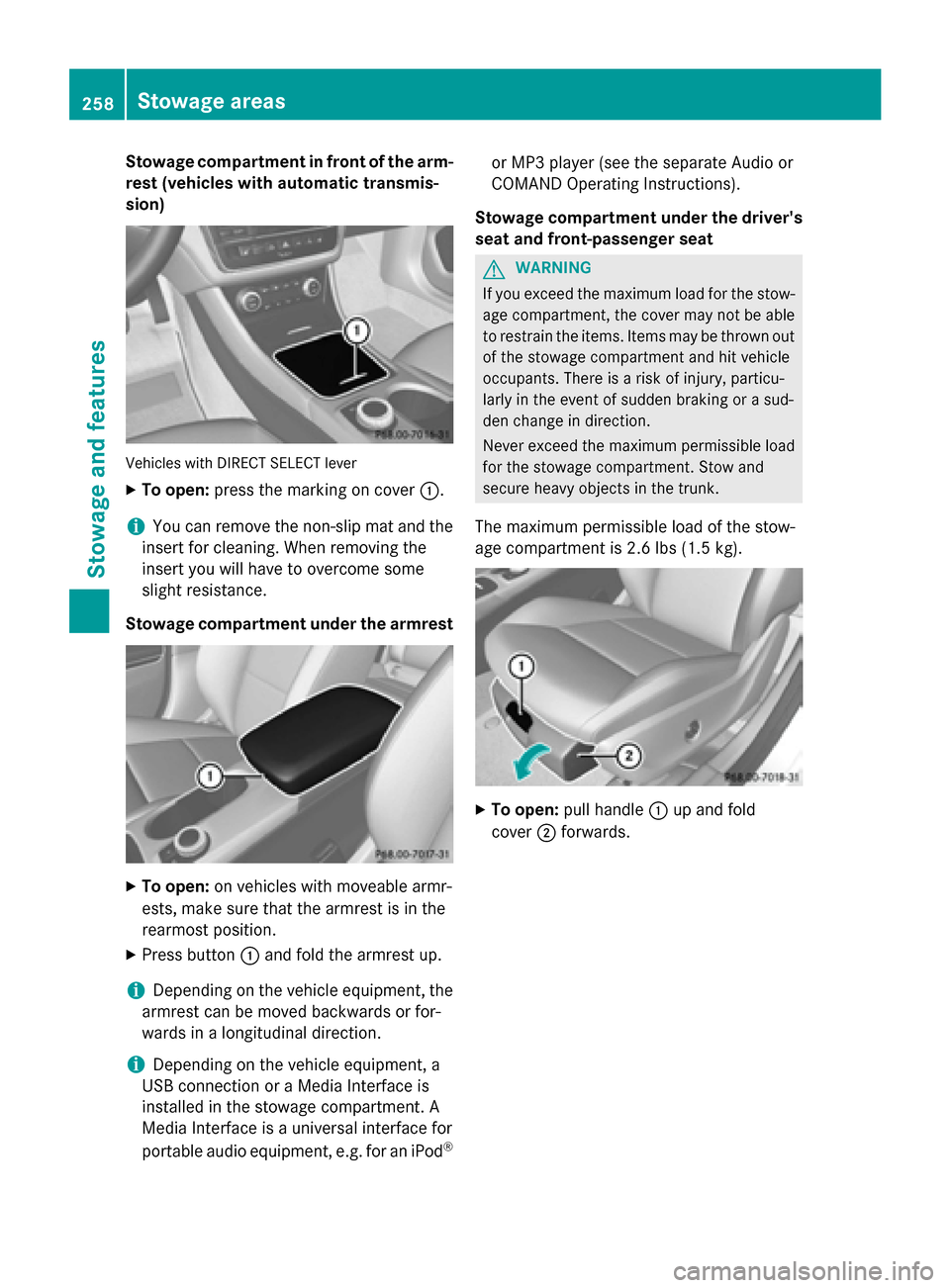
Stowage compartment in front of the arm-
rest (vehicles with automatic transmis-
sion) Vehicles with DIRECT SELECT lever
X To open: press the marking on cover 0043.
i You can remove the non-slip mat and the
insert for cleaning. When removing the
insert you will have to overcome some
slight resistance.
Stowage compartment under the armrest X
To open: on vehicles with moveable armr-
ests, make sure that the armrest is in the
rearmost position.
X Press button 0043and fold the armrest up.
i Depending on the vehicle equipment, the
armrest can be moved backwards or for-
wards in a longitudinal direction.
i Depending on the vehicle equipment, a
USB connection or a Media Interface is
installed in the stowage compartment. A
Media Interface is a universal interface for
portable audio equipment, e.g. for an iPod ®or MP3 player (see the separate Audio or
COMAND Operating Instructions).
Stowage compartment under the driver's seat and front-passenger seat G
WARNING
If you exceed the maximum load for the stow- age compartment, the cover may not be ableto restrain the items. Items may be thrown out
of the stowage compartment and hit vehicle
occupants. There is a risk of injury, particu-
larly in the event of sudden braking or a sud-
den change in direction.
Never exceed the maximum permissible load
for the stowage compartment. Stow and
secure heavy objects in the trunk.
The maximum permissible load of the stow-
age compartment is 2.6 lbs (1.5 kg). X
To open: pull handle 0043up and fold
cover 0044forwards. 258
Stowage areasStowage and features
Page 261 of 358
Stowage space in the rear
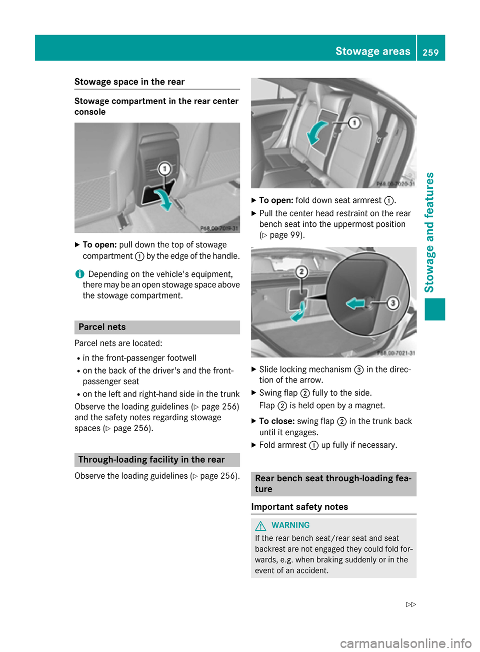
Stowage compartment in the rear center
console
X
To open: pull down the top of stowage
compartment 0043by the edge of the handle.
i Depending on the vehicle's equipment,
there may be an open stowage space above the stowage compartment. Parcel nets
Parcel nets are located: R in the front-passenger footwell
R on the back of the driver's and the front-
passenger seat
R on the left and right-hand side in the trunk
Observe the loading guidelines (Y page 256)
and the safety notes regarding stowage
spaces (Y page 256). Through-loading facility in the rear
Observe the loading guidelines (Y page 256). X
To open: fold down seat armrest 0043.
X Pull the center head restraint on the rear
bench seat into the uppermost position
(Y page 99). X
Slide locking mechanism 0087in the direc-
tion of the arrow.
X Swing flap 0044fully to the side.
Flap 0044is held open by a magnet.
X To close: swing flap 0044in the trunk back
until it engages.
X Fold armrest 0043up fully if necessary. Rear bench seat through-loading fea-
ture
Important safety notes G
WARNING
If the rear bench seat/rear seat and seat
backrest are not engaged they could fold for- wards, e.g. when braking suddenly or in the
event of an accident. Stowage areas
259Stowage and features
Z
Page 262 of 358
R
The vehicle occupant would thereby be
pushed into the seat belt by the rear bench
seat/rear seat or by the seat backrest. The
seat belt can no longer offer the intended
level of protection and could even cause
injuries.
R Objects or loads in the trunk cannot be
restrained by the seat backrest.
There is an increased risk of injury.
Before every trip, make sure that the seat
backrests and the rear bench seat/rear seat
are engaged.
! Before folding the backrest in the rear
compartment forwards, make sure that the rear compartment armrest and the
cupholder are folded in. They may other-
wise be damaged.
Observe the loading guidelines (Y page 256).
Folding the rear seat backrest forwards and back Folding the rear seat backrest forward
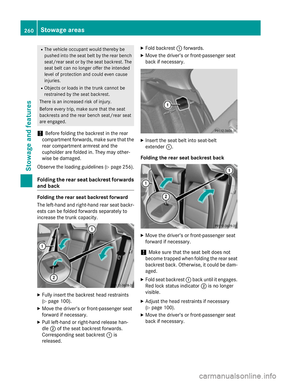
The left-hand and right-hand rear seat backr-
ests can be folded forwards separately to
increase the trunk capacity. X
Fully insert the backrest head restraints
(Y page 100).
X Move the driver's or front-passenger seat
forward if necessary.
X Pull left-hand or right-hand release han-
dle 0044of the seat backrest forwards.
Corresponding seat backrest 0043is
released. X
Fold backrest 0043forwards.
X Move the driver's or front-passenger seat
back if necessary. X
Insert the seat belt into seat-belt
extender 0043.
Folding the rear seat backrest back X
Move the driver's or front-passenger seat
forward if necessary.
! Make sure that the seat belt does not
become trapped when folding the rear seat backrest back. Otherwise, it could be dam-
aged.
X Fold seat backrest 0043back until it engages.
Red lock status indicator 0044is no longer
visible.
X Adjust the head restraints if necessary
(Y page 100).
X Move the driver's or front-passenger seat
back if necessary. 260
Stowage areasStowage and features
Page 263 of 358
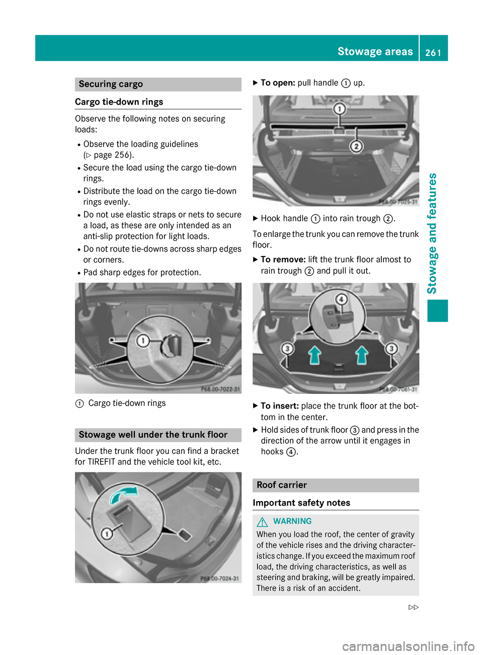
Securing cargo
Cargo tie-down rings Observe the following notes on securing
loads:
R Observe the loading guidelines
(Y page 256).
R Secure the load using the cargo tie-down
rings.
R Distribute the load on the cargo tie-down
rings evenly.
R Do not use elastic straps or nets to secure
a load, as these are only intended as an
anti-slip protection for light loads.
R Do not route tie-downs across sharp edges
or corners.
R Pad sharp edges for protection. 0043
Cargo tie-down rings Stowage well under the trunk floor
Under the trunk floor you can find a bracket
for TIREFIT and the vehicle tool kit, etc. X
To open: pull handle 0043up. X
Hook handle 0043into rain trough 0044.
To enlarge the trunk you can remove the trunk floor.
X To remove: lift the trunk floor almost to
rain trough 0044and pull it out. X
To insert: place the trunk floor at the bot-
tom in the center.
X Hold sides of trunk floor 0087and press in the
direction of the arrow until it engages in
hooks 0085. Roof carrier
Important safety notes G
WARNING
When you load the roof, the center of gravity
of the vehicle rises and the driving character- istics change. If you exceed the maximum roof
load, the driving characteristics, as well as
steering and braking, will be greatly impaired.There is a risk of an accident. Stowage areas
261Stowage and features
Z
Page 264 of 358
Never exceed the maximum roof load and
adjust your driving style.
! Mercedes-Benz recommends that you
only use roof carriers that have been tested and approved for Mercedes-Benz vehicles.
This helps to prevent damage to the vehi-
cle.
Position the load on the roof rack in such a
way that the vehicle will not sustain dam-
age even when it is in motion.
Depending on the vehicle equipment,
ensure that when the roof carrier is instal-
led you can:
R open the panorama roof with power tilt/
sliding panel fully
R open the trunk lid fully
The maximum roof load is 165 lbs (75 kg).
An incorrectly secured roof carrier or roof
load may become detached from the vehicle.
You must therefore ensure that you observe
the roof carrier manufacturer's installation
instructions.
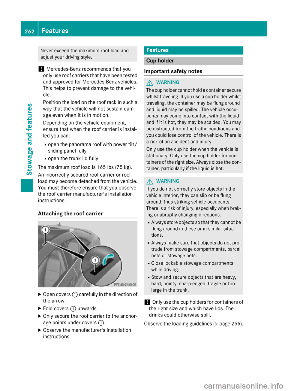
Attaching the roof carrier X
Open covers 0043carefully in the direction of
the arrow.
X Fold covers 0043upwards.
X Only secure the roof carrier to the anchor-
age points under covers 0043.
X Observe the manufacturer's installation
instructions. Features
Cup holder
Important safety notes G
WARNING
The cup holder cannot hold a container secure whilst traveling. If you use a cup holder whilsttraveling, the container may be flung around
and liquid may be spilled. The vehicle occu-
pants may come into contact with the liquid
and if it is hot, they may be scalded. You may
be distracted from the traffic conditions and
you could lose control of the vehicle. There is a risk of an accident and injury.
Only use the cup holder when the vehicle is
stationary. Only use the cup holder for con-
tainers of the right size. Always close the con-
tainer, particularly if the liquid is hot. G
WARNING
If you do not correctly store objects in the
vehicle interior, they can slip or be flung
around, thus striking vehicle occupants.
There is a risk of injury, especially when brak- ing or abruptly changing directions.
R Always store objects so that they cannot be
flung around in these or in similar situa-
tions.
R Always make sure that objects do not pro-
trude from stowage compartments, parcel
nets or stowage nets.
R Close lockable stowage compartments
while driving.
R Stow and secure objects that are heavy,
hard, pointy, sharp-edged, fragile or too
large in the trunk.
! Only use the cup holders for containers of
the right size and which have lids. The
drinks could otherwise spill.
Observe the loading guidelines (Y page 256).262
FeaturesStowage and features
Page 268 of 358
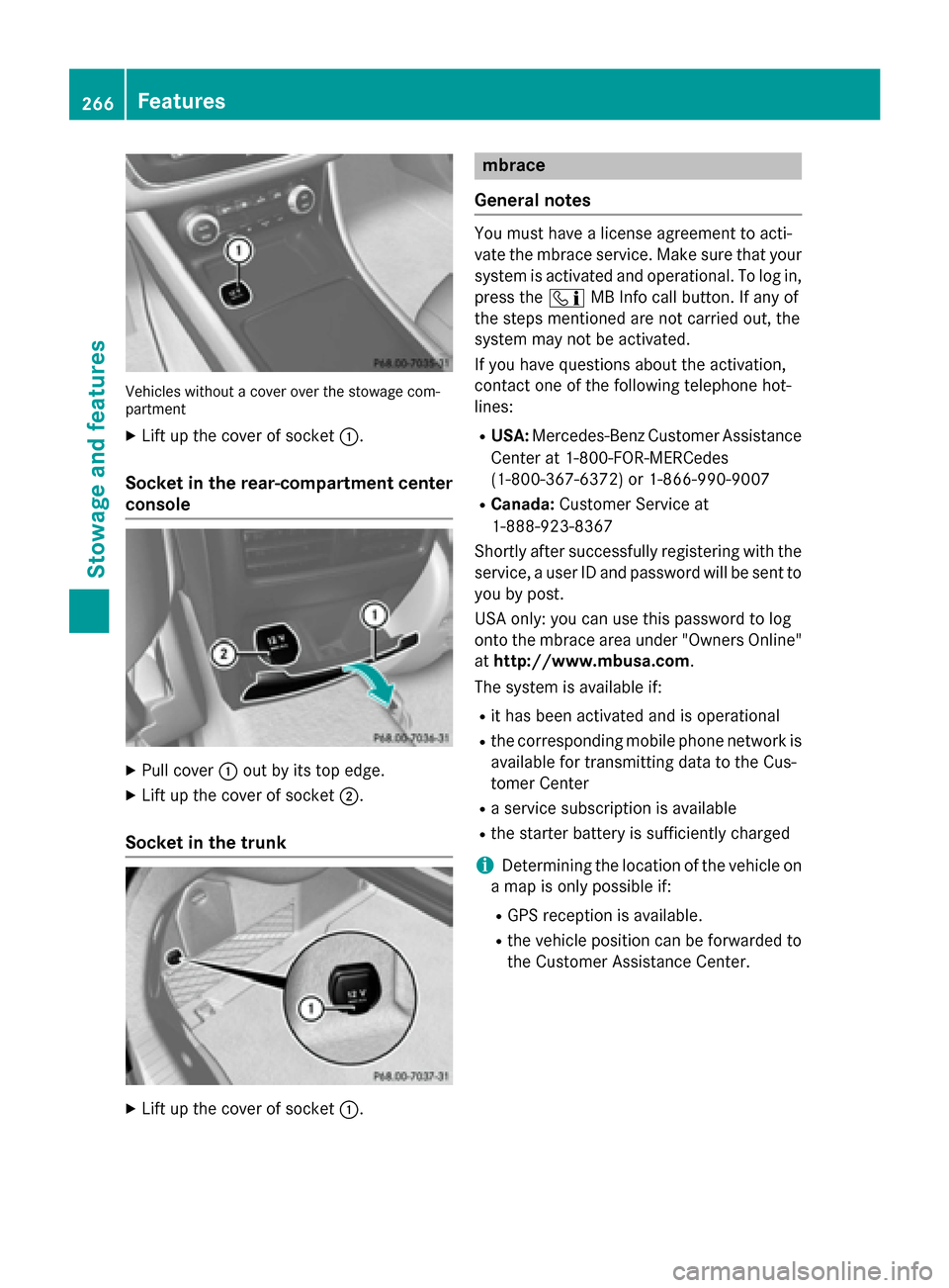
Vehicles without a cover over the stowage com-
partment
X Lift up the cover of socket 0043.
Socket in the rear-compartment center
console X
Pull cover 0043out by its top edge.
X Lift up the cover of socket 0044.
Socket in the trunk X
Lift up the cover of socket 0043. mbrace
General notes You must have a license agreement to acti-
vate the mbrace service. Make sure that your
system is activated and operational. To log in,
press the 00D9MB Info call button. If any of
the steps mentioned are not carried out, the
system may not be activated.
If you have questions about the activation,
contact one of the following telephone hot-
lines:
R USA: Mercedes-Benz Customer Assistance
Center at 1-800-FOR-MERCedes
(1-800-367-6372) or 1-866-990-9007
R Canada: Customer Service at
1-888-923-8367
Shortly after successfully registering with the
service, a user ID and password will be sent to you by post.
USA only: you can use this password to log
onto the mbrace area under "Owners Online"
at http://www.mbusa.com.
The system is available if:
R it has been activated and is operational
R the corresponding mobile phone network is
available for transmitting data to the Cus-
tomer Center
R a service subscription is available
R the starter battery is sufficiently charged
i Determining the location of the vehicle on
a map is only possible if:
R GPS reception is available.
R the vehicle position can be forwarded to
the Customer Assistance Center. 266
FeaturesStowage and features
Page 281 of 358

Calibrating the compass
X
Make sure that there is sufficient space for
you to drive in a circle without impeding
traffic.
In order to calibrate the compass correctly,
do the following:
R calibrate the compass in the open and not
in the vicinity of steel structures or high-
voltage transmission lines.
R switch off electrical consumers such as the
climate control, windshield wipers or rear
window defroster.
R close all doors and the trunk lid.
X Switch on the ignition.
X Push a round pen into opening 0087
(Y page 278) for approximately six sec-
onds, until symbol C
C is shown in compass
display 0044(Ypage 278).
X Drive your vehicle in a full circle at approx-
imately 3 mph (5 km/h) to 6 mph
(10 km/h).
When the calibration has successfully been completed, the current direction is shown
in compass display 0044(Ypage 278). Floormat on the driver's side
G
WARNING
Objects in the driver's footwell can restrict the pedal travel or obstruct a depressed pedal.
The operating and road safety of the vehicle is
jeopardized. There is a risk of an accident.
Make sure that all objects in the vehicle are
stowed correctly, and that they cannot enter
the driver's footwell. Install the floormats
securely and as specified in order to ensure
sufficient clearance for the pedals. Do not use loose floormats and do not place floormats on
top of one another. X
Slide the seat backwards.
X To install: place the floormat in the foot-
well.
X Press safety catch knobs 0043onto retain-
ers 0044.
X To remove: pull the floormat off retain-
ers 0044.
X Remove the floormat. Features
279Stowage and features Z
Page 298 of 358
Useful information
i This Operator's manual describes all
models and all standard and optional equip- ment of your vehicle available at the time of
publication of the Operator's manual.
Country-specific differences are possible.
Please note that your vehicle may not be
equipped with all features described. This
also applies to safety-related systems and
functions.
i Read the information on qualified special-
ist workshops (Y page 26). Where will I find...?
Vehicle tool kit
General notes Vehicles with a TIREFIT kit: the TIREFIT kit is
located in the stowage well under the trunk
floor.
Vehicles with a tire-change tool kit: the tire-
change tool kit is in the stowage well under
the trunk floor.
i Apart from certain country-specific varia-
tions, the vehicles are not equipped with a
tire-change tool kit. Some tools for chang-
ing a wheel are specific to the vehicle. For
more information on which tire changing
tools are required and approved to perform
a wheel change on your vehicle, consult a
qualified specialist workshop.
Tools required for changing a wheel may
include, for example:
R Jack
R Wheel chock
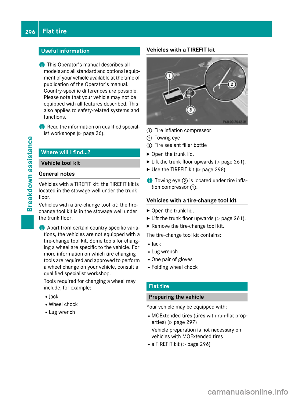
R Lug wrench Vehicles with a TIREFIT kit 0043
Tire inflation compressor
0044 Towing eye
0087 Tire sealant filler bottle
X Open the trunk lid.
X Lift the trunk floor upwards (Y page 261).
X Use the TIREFIT kit (Y page 298).
i Towing eye
0044is located under tire infla-
tion compressor 0043.
Vehicles with a tire-change tool kit X
Open the trunk lid.
X Lift the trunk floor upwards (Y page 261).
X Remove the tire-change tool kit.
The tire-change tool kit contains:
R Jack
R Lug wrench
R One pair of gloves
R Folding wheel chock Flat tire
Preparing the vehicle
Your vehicle may be equipped with:
R MOExtended tires (tires with run-flat prop-
erties) (Y page 297)
Vehicle preparation is not necessary on
vehicles with MOExtended tires
R a TIREFIT kit (Y page 296)296
Flat tireBreakdown assistance