2014 MERCEDES-BENZ C-CLASS ESTATE headlamp
[x] Cancel search: headlampPage 146 of 489
Replacing front bulbs (vehicles with
halogen headlamps)
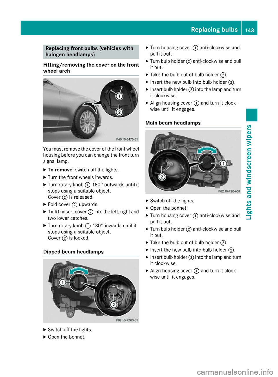
Fitting/removing the cover on the front wheel arch You must remove the cover of the front wheel
housing before you can change the front turn signal lamp.
X To remove: switch off the lights.
X Turn the front wheels inwards.
X Turn rotary knob :180° outwards until it
stops using a suitable object.
Cover ;is released.
X Fold cover ;upwards.
X To fit: insert cover ;into the left, right and
two lower catches.
X Turn rotary knob :180° inwards until it
stops using a suitable object.
Cover ;is locked.
Dipped-beam headlamps X
Switch off the lights.
X Open the bonnet. X
Turn housing cover :anti-clockwise and
pull it out.
X Turn bulb holder ;anti-clockwise and pull
it out.
X Take the bulb out of bulb holder ;.
X Insert the new bulb into bulb holder ;.
X Insert bulb holder ;into the lamp and turn
it clockwise.
X Align housing cover :and turn it clock-
wise until it engages.
Main-beam headlamps X
Switch off the lights.
X Open the bonnet.
X Turn housing cover :anti-clockwise and
pull it out.
X Turn bulb holder ;anti-clockwise and pull
it out.
X Take the bulb out of bulb holder ;.
X Insert the new bulb into bulb holder ;.
X Insert bulb holder ;into the lamp and turn
it clockwise.
X Align housing cover :and turn it clock-
wise until it engages. Replacing bulbs
143Lights and windscreen wipers Z
Page 147 of 489
Turn signals
X
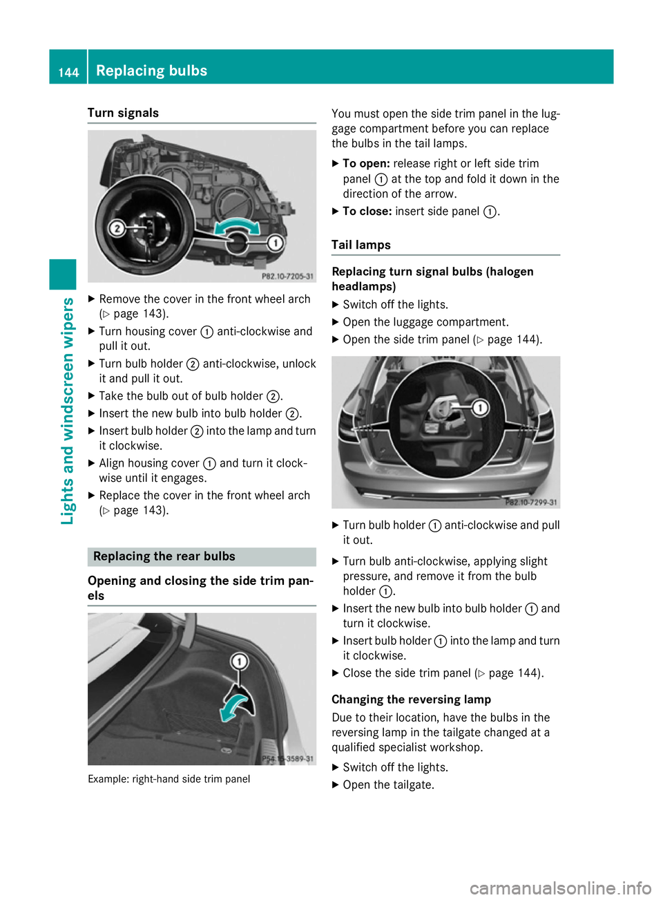
Remove the cover in the front wheel arch
(Y page 143).
X Turn housing cover :anti-clockwise and
pull it out.
X Turn bulb holder ;anti-clockwise, unlock
it and pull it out.
X Take the bulb out of bulb holder ;.
X Insert the new bulb into bulb holder ;.
X Insert bulb holder ;into the lamp and turn
it clockwise.
X Align housing cover :and turn it clock-
wise until it engages.
X Replace the cover in the front wheel arch
(Y page 143). Replacing the rear bulbs
Opening and closing the side trim pan-
els Example: right-hand side trim panel You must open the side trim panel in the lug-
gage compartment before you can replace
the bulbs in the tail lamps.
X To open: release right or left side trim
panel :at the top and fold it down in the
direction of the arrow.
X To close: insert side panel :.
Tail lamps Replacing turn signal bulbs (halogen
headlamps)
X Switch off the lights.
X Open the luggage compartment.
X Open the side trim panel (Y page 144). X
Turn bulb holder :anti-clockwise and pull
it out.
X Turn bulb anti-clockwise, applying slight
pressure, and remove it from the bulb
holder :.
X Insert the new bulb into bulb holder :and
turn it clockwise.
X Insert bulb holder :into the lamp and turn
it clockwise.
X Close the side trim panel (Y page 144).
Changing the reversing lamp
Due to their location, have the bulbs in the
reversing lamp in the tailgate changed at a
qualified specialist workshop. X Switch off the lights.
X Open the tailgate. 144
Replacing bulbsLights and
windscreen wipers
Page 148 of 489
Example: right-hand side handle
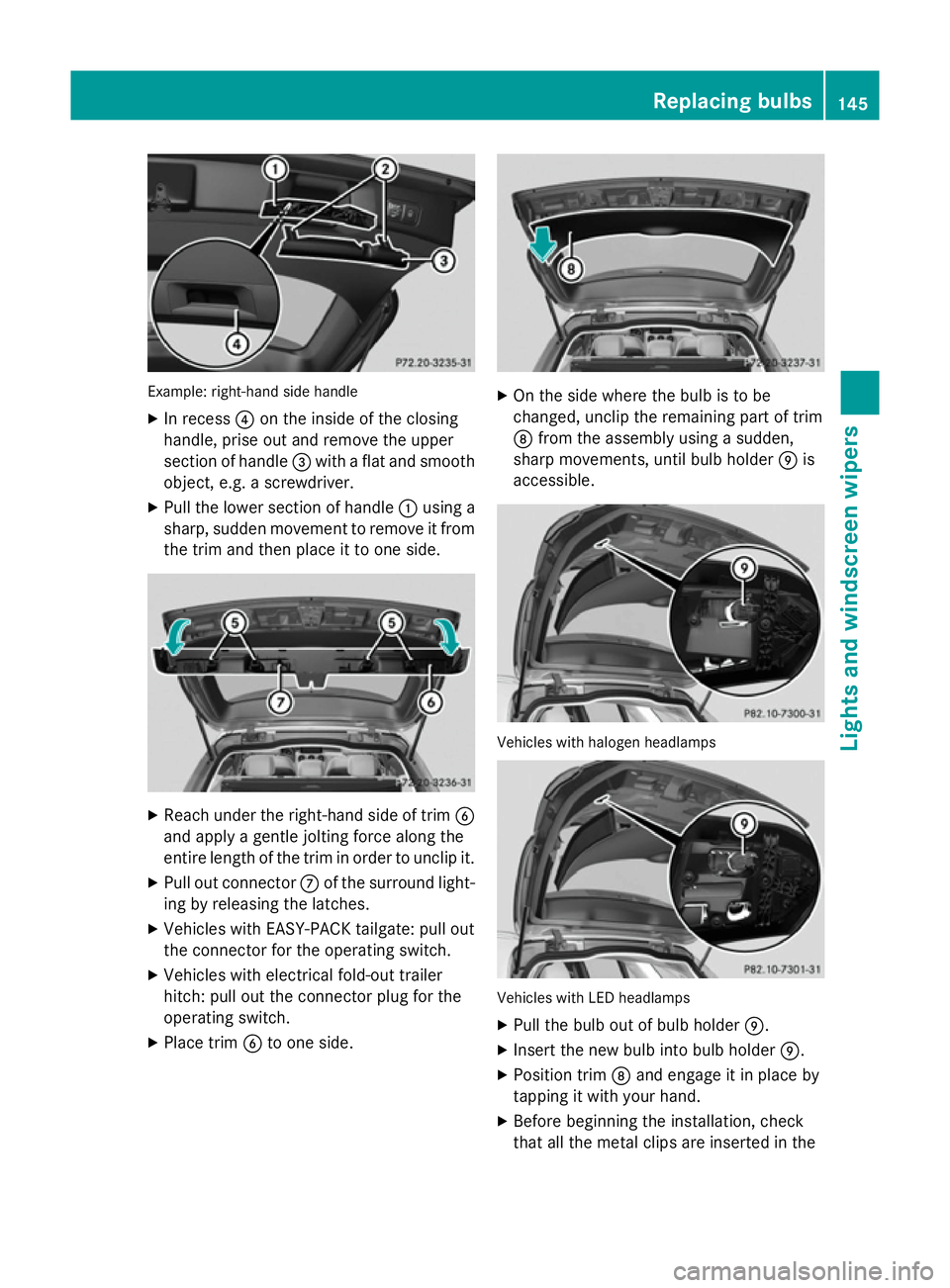
X In recess ?on the inside of the closing
handle, prise out and remove the upper
section of handle =with a flat and smooth
object, e.g. a screwdriver.
X Pull the lower section of handle :using a
sharp, sudden movement to remove it from the trim and then place it to one side. X
Reach under the right-hand side of trim B
and apply a gentle jolting force along the
entire length of the trim in order to unclip it.
X Pull out connector Cof the surround light-
ing by releasing the latches.
X Vehicles with EASY-PACK tailgate: pull out
the connector for the operating switch.
X Vehicles with electrical fold-out trailer
hitch: pull out the connector plug for the
operating switch.
X Place trim Bto one side. X
On the side where the bulb is to be
changed, unclip the remaining part of trim
D from the assembly using a sudden,
sharp movements, until bulb holder Eis
accessible. Vehicles with halogen headlamps
Vehicles with LED headlamps
X Pull the bulb out of bulb holder E.
X Insert the new bulb into bulb holder E.
X Position trim Dand engage it in place by
tapping it with your hand.
X Before beginning the installation, check
that all the metal clips are inserted in the Replacing bulbs
145Lights andwindscreen wipers Z
Page 316 of 489
X
Switch on the head-up display
(Y page 298).
X Use ò on the steering wheel to call up
the list of menus.
X Press the :or9 button on the steer-
ing wheel to select the Settings
Settings menu.
X Confirm by pressing aon the steering
wheel.
X Press the :or9 button to select the
Head-up display
Head-up display submenu.
X Press ato confirm.
X Press the :or9 button to select the
Brightness
Brightness function.
X Press the abutton to save the setting.
X Press the :or9 button to set the
brightness from Level +5
Level +5(bright) to
Level -5
Level -5 (dark).
X Press the aor% button to save the
setting.
Light submenu Switching the Intelligent Light System
on/off
X Use ò on the steering wheel to call up
the list of menus.
X Press the :or9 button on the steer-
ing wheel to select the Settings
Settings menu.
X Confirm by pressing aon the steering
wheel.
X Press the :or9 button to select the
Lights
Lights submenu.
X Press ato confirm.
X Press the :or9 button to select the
Intelligent Light System
Intelligent Light System function.
If the Intelligent Light System
Intelligent Light System func-
tion has been switched on, the cone of light
and the Lsymbol in the multifunction
display are shown in white.
X Press the abutton to save the setting.
When you activate the Intelligent
IntelligentLight
Light
System
System , you activate the following functions:
R Motorway mode
R Active light function R
Cornering light function
R Extended range foglamps
If you set the dipped-beam headlamps for
driving on the right/left, the multifunction
display shows the Inactive for left-
Inactive for left-
side traffic side traffic orInactive for right-
Inactive for right-
side traffic
side traffic display message instead of
the Intelligent
Intelligent Light
LightSystem
System function in
the Lights
Lights submenu (Y page 313). This dis-
play message will only appear if the setting for
driving on the left/right is set opposite to your
vehicle's country version.
Further information on the Intelligent Light
System (Y page 138).
Setting the dipped-beam headlamps for
driving on the left/right
This function is only available on vehicles with
the Intelligent Light System.
You can use this function to switch between
symmetrical and asymmetrical dipped beam
(Y page 134).
X Use ò on the steering wheel to call up
the list of menus.
X Press the :or9 button on the steer-
ing wheel to select the Settings Settingsmenu.
X Confirm by pressing aon the steering
wheel.
X Press the :or9 button to select the
Lights
Lights submenu.
X Press ato confirm.
X Press :or9 to select the Dipped
Dipped
beams Setting for
beams Setting for function.
You will see the selected setting: right-
right-
side traffic
side traffic orleft-side traffic
left-side traffic.
X Press the abutton to save the setting.
If you change the setting, conversion does
not take place until the next time the vehi-
cle is stationary.
If you set the dipped-beam headlamps for
driving on the right/left, then motorway
mode and the extended range foglamps are
unavailable. These are only deactivated if the setting for driving on the left/right is set
opposite to your vehicle's country version. Menus and submenus
313On-board computer and displays Z
Page 317 of 489
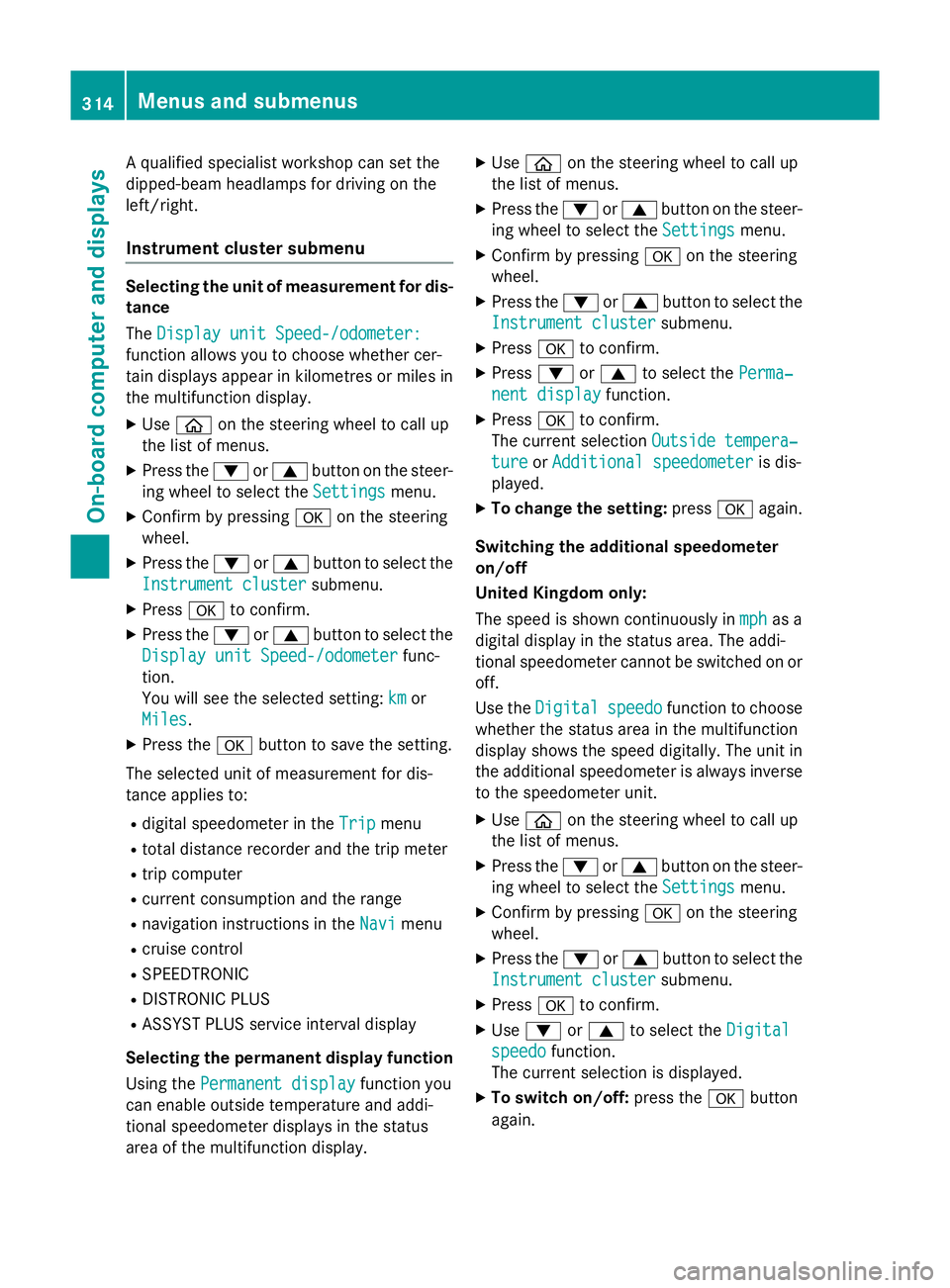
A qualified specialist workshop can set the
dipped-beam headlamps for driving on the
left/right.
Instrument cluster submenu Selecting the unit of measurement for dis-
tance
The Display unit Speed-/odometer:
Display unit Speed-/odometer:
function allows you to choose whether cer-
tain displays appear in kilometres or miles in the multifunction display.
X Use ò on the steering wheel to call up
the list of menus.
X Press the :or9 button on the steer-
ing wheel to select the Settings Settingsmenu.
X Confirm by pressing aon the steering
wheel.
X Press the :or9 button to select the
Instrument cluster
Instrument cluster submenu.
X Press ato confirm.
X Press the :or9 button to select the
Display unit Speed-/odometer
Display unit Speed-/odometer func-
tion.
You will see the selected setting: km kmor
Miles
Miles.
X Press the abutton to save the setting.
The selected unit of measurement for dis-
tance applies to:
R digital speedometer in the Trip
Tripmenu
R total distance recorder and the trip meter
R trip computer
R current consumption and the range
R navigation instructions in the Navi
Navi menu
R cruise control
R SPEEDTRONIC
R DISTRONIC PLUS
R ASSYST PLUS service interval display
Selecting the permanent display function
Using the Permanent display
Permanent display function you
can enable outside temperature and addi-
tional speedometer displays in the status
area of the multifunction display. X
Use ò on the steering wheel to call up
the list of menus.
X Press the :or9 button on the steer-
ing wheel to select the Settings
Settings menu.
X Confirm by pressing aon the steering
wheel.
X Press the :or9 button to select the
Instrument cluster Instrument cluster submenu.
X Press ato confirm.
X Press :or9 to select the Perma‐
Perma‐
nent display
nent display function.
X Press ato confirm.
The current selection Outside tempera‐
Outside tempera‐
ture
ture orAdditional speedometer
Additional speedometer is dis-
played.
X To change the setting: pressaagain.
Switching the additional speedometer
on/off
United Kingdom only:
The speed is shown continuously in mph mphas a
digital display in the status area. The addi-
tional speedometer cannot be switched on or off.
Use the Digital Digital speedo
speedofunction to choose
whether the status area in the multifunction
display shows the speed digitally. The unit in
the additional speedometer is always inverse to the speedometer unit.
X Use ò on the steering wheel to call up
the list of menus.
X Press the :or9 button on the steer-
ing wheel to select the Settings Settingsmenu.
X Confirm by pressing aon the steering
wheel.
X Press the :or9 button to select the
Instrument cluster
Instrument cluster submenu.
X Press ato confirm.
X Use : or9 to select the Digital
Digital
speedo
speedo function.
The current selection is displayed.
X To switch on/off: press theabutton
again. 314
Menus and submenusOn-board computer and displays
Page 334 of 489
Display messages
Possible causes/consequences and
M
MSolutions front-passenger front airbag deactivation system has disa-
bled the front-passenger front airbag (Y
page 54).
R the display messages Front-passenger Front-passengerairbag
airbagenabled
enabled
See
See Owner's
Owner's Manual
ManualorFront-passenger
Front-passenger airbag
airbagdisa‐
disa‐
bled See Owner's Manual
bled See Owner's Manual must not appear in the multi-
function display.
X Wait for a period of at least 60 seconds until the necessary sys-
tem checks have been completed.
X Make sure that the display messages do not appear in the mul-
tifunction display.
If these conditions are met, the front-passenger seat can be occu- pied again. Whether the PASSENGER AIRBAG OFF or ON indicator
lamp remains lit or goes out depends on how the automatic front- passenger front airbag deactivation system classifies the occu-
pant.
If the conditions are not met, the system is not operating correctly.
X Visit a qualified specialist workshop immediately.
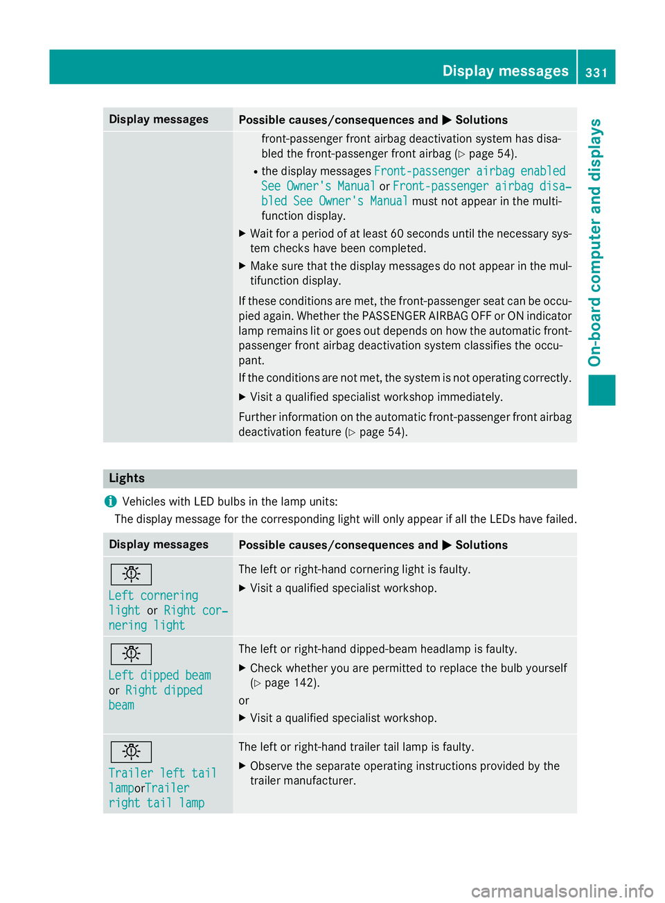
Further information on the automatic front-passenger front airbag deactivation feature (Y page 54).Lights
i Vehicles with LED bulbs in the lamp units:
The display message for the corresponding light will only appear if all the LEDs have failed. Display messages
Possible causes/consequences and
M MSolutions b
Left cornering Left cornering
light light
orRight cor‐
Right cor‐
nering light
nering light The left or right-hand cornering light is faulty.
X Visit a qualified specialist workshop. b
Left dipped beam Left dipped beam
or
Right dipped Right dipped
beam beam The left or right-hand dipped-beam headlamp is faulty.
X Check whether you are permitted to replace the bulb yourself
(Y page 142).
or
X Visit a qualified specialist workshop. b
Trailer left tail Trailer left tail
lamp lampor
Trailer
Trailer
right tail lamp right tail lamp The left or right-hand trailer tail lamp is faulty.
X Observe the separate operating instructions provided by the
trailer manufacturer. Display
messages
331On-board computer and displays Z
Page 336 of 489
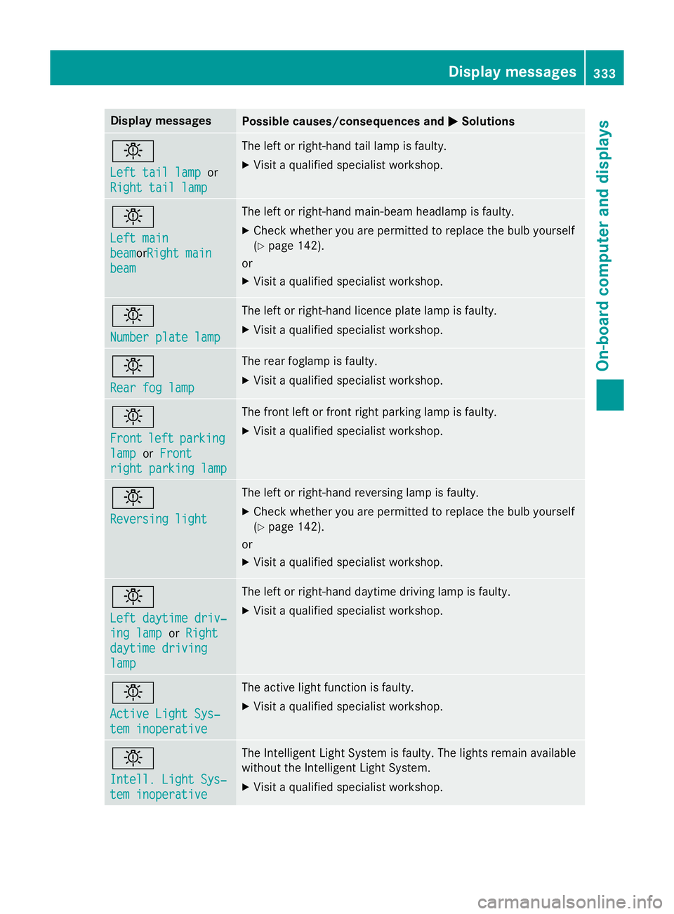
Display messages
Possible causes/consequences and
M
MSolutions b
Left tail lamp Left tail lamp
or
Right tail lamp
Right tail lamp The left or right-hand tail lamp is faulty.
X Visit a qualified specialist workshop. b
Left main Left main
beam beamor
Right main
Right main
beam
beam The left or right-hand main-beam headlamp is faulty.
X Check whether you are permitted to replace the bulb yourself
(Y page 142).
or
X Visit a qualified specialist workshop. b
Number plate lamp Number plate lamp The left or right-hand licence plate lamp is faulty.
X Visit a qualified specialist workshop. b
Rear fog lamp Rear fog lamp The rear foglamp is faulty.
X Visit a qualified specialist workshop. b
Front Front
left
leftparking
parking
lamp
lamp orFront
Front
right parking lamp
right parking lamp The front left or front right parking lamp is faulty.
X Visit a qualified specialist workshop. b
Reversing light Reversing light The left or right-hand reversing lamp is faulty.
X Check whether you are permitted to replace the bulb yourself
(Y page 142).
or
X Visit a qualified specialist workshop. b
Left daytime driv‐ Left daytime driv‐
ing lamp ing lamp
orRight
Right
daytime driving
daytime driving
lamp lamp The left or right-hand daytime driving lamp is faulty.
X Visit a qualified specialist workshop. b
Active Light Sys‐ Active Light Sys‐
tem inoperative tem inoperative The active light function is faulty.
X Visit a qualified specialist workshop. b
Intell. Light Sys‐ Intell. Light Sys‐
tem inoperative tem inoperative The Intelligent Light System is faulty. The lights remain available
without the Intelligent Light System.
X Visit a qualified specialist workshop. Display
messages
333On-board computer and displays Z
Page 480 of 489
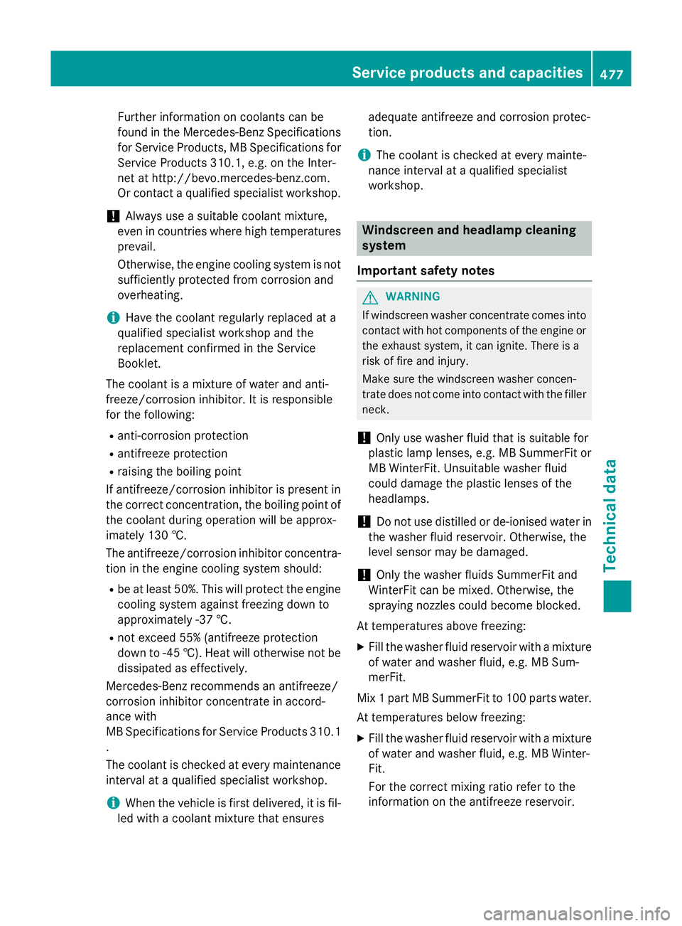
Further information on coolants can be
found in the Mercedes-Benz Specifications for Service Products, MB Specifications for Service Products 310.1, e.g. on the Inter-
net at http://bevo.mercedes-benz.com.
Or contact a qualified specialist workshop.
! Always use a suitable coolant mixture,
even in countries where high temperatures prevail.
Otherwise, the engine cooling system is not
sufficiently protected from corrosion and
overheating.
i Have the coolant regularly replaced at a
qualified specialist workshop and the
replacement confirmed in the Service
Booklet.
The coolant is a mixture of water and anti-
freeze/corrosion inhibitor. It is responsible
for the following:
R anti-corrosion protection
R antifreeze protection
R raising the boiling point
If antifreeze/corrosion inhibitor is present in
the correct concentration, the boiling point of
the coolant during operation will be approx-
imately 130 †.
The antifreeze/corrosion inhibitor concentra- tion in the engine cooling system should:
R be at least 50%. This will protect the engine
cooling system against freezing down to
approximately -37 †.
R not exceed 55% (antifreeze protection
down to -45 †). Heat will otherwise not be
dissipated as effectively.
Mercedes-Benz recommends an antifreeze/
corrosion inhibitor concentrate in accord-
ance with
MB Specifications for Service Products 310.1
.
The coolant is checked at every maintenance interval at a qualified specialist workshop.
i When the vehicle is first delivered, it is fil-
led with a coolant mixture that ensures adequate antifreeze and corrosion protec-
tion.
i The coolant is checked at every mainte-
nance interval at a qualified specialist
workshop. Windscreen and headlamp cleaning
system
Important safety notes G
WARNING
If windscreen washer concentrate comes into contact with hot components of the engine or
the exhaust system, it can ignite. There is a
risk of fire and injury.
Make sure the windscreen washer concen-
trate does not come into contact with the filler neck.
! Only use washer fluid that is suitable for
plastic lamp lenses, e.g. MB SummerFit or
MB WinterFit. Unsuitable washer fluid
could damage the plastic lenses of the
headlamps.
! Do not use distilled or de-ionised water in
the washer fluid reservoir. Otherwise, the
level sensor may be damaged.
! Only the washer fluids SummerFit and
WinterFit can be mixed. Otherwise, the
spraying nozzles could become blocked.
At temperatures above freezing: X Fill the washer fluid reservoir with a mixture
of water and washer fluid, e.g. MB Sum-
merFit.
Mix 1 part MB SummerFit to 100 parts water.
At temperatures below freezing:
X Fill the washer fluid reservoir with a mixture
of water and washer fluid, e.g. MB Winter-
Fit.
For the correct mixing ratio refer to the
information on the antifreeze reservoir. Service products and capacities
477Technical data Z