Page 544 of 1206
Maintenance
86
7
FuseFuse ratingSymbolFuse NameProtected component
FUSE
20A5TCU1TCU
40AFUEL
HEATERFUEL HEATER RELAY
40A7EMSEMS BOX (Fuse No. - 1/2/3/4/5/6/7/8/9)
50AB+3B+3Inner Fuse Panel (Leak Current Autocut Device, Fuse No. - 6/19/20/17/32/26/25)
50ABLOWERBLOWER RELAY
10AA/CONA/C Control Module
10AWIPER FRTECU, Rain Sensor
10AB/UP
LAMPB/UP LPM/T : Back-up Lamp Switch, A/T : Transaxle Range Switch, TCU
15A4ECU4Smart Key Control Module, Immobilizer Module, ECU, Air Flow Sensor,
Fuel Water Sensor
10A3ABS3ESC Control Module, ABS Control Module, Yaw Rate Sensor, HAC, ESS RELAY
15A6TCU2Transaxle Range Switch, TCU
JD eng 7.QXP 5/6/2013 9:51 AM Page 86
Page 545 of 1206
787
Maintenance
SymbolRelay NameType
LOCOOLING FAN LOW RELAYPLUG MICRO
HICOOLING FAN HIGH RELAYPLUG MICRO
ESSESS RELAYPLUG MICRO
BLOWER RELAYPLUG MICRO
RR
HTDREAR DEFOGGER RELAYPLUG MICRO
4 (IG2)IG2 RELAYPLUG MICRO
FRT WIPER RELAYPLUG MICRO
3 (IG1)IG1 RELAYPLUG MICRO
1START RELAYPLUG MICRO
2 (ACC)ACC RELAYPLUG MICRO
FUEL HEATER RELAYPLUG MINI
HACHAC RELAYPLUG MICRO
Fuse ratingSymbolFuse NameRelay Name
15ASPARESPARE-
15AHORNHORN RELAY
10A2ECU2Oil Level Sensor, Fuel
Pressure Control Valve
20ASPARESPARE-
10A9SENSOR2
E/R Fuse & Relay Box
(COOLING FAN LOW RELAY),Lambda Sensor (D4FB), Stop Lamp Switch
20A1ECU1ECU
10A8SENSOR1
DSL Box (PTC1 RELAY,
GLOW RELAY),
VGT Control Sensor,
Camshaft Position Sensor,
Electrical EGR Valve
JD eng 7.QXP 5/6/2013 9:51 AM Page 87
Page 546 of 1206
Maintenance
88
7
Engine compartment fuse panel
(Diesel engine only)
✽✽ NOTICE
The actual fuse/relay panel label may
differ from equipped items.
DescriptionFuse ratingProtected Component
80AGlow Relay
PTC 150APTC 1 Relay
PTC 250APTC 2 Relay
PTC 350APTC 3 Relay
OGD071024
OGDE071059
JD eng 7.QXP 5/6/2013 9:51 AM Page 88
Page 596 of 1206

Index
6
I
Fuse switch . . . . . . . . . . . . . . . . . . . . . . . . . . . . . . . . 7-68
Fuse/relay panel description . . . . . . . . . . . . . . . . . . 7-71
Inner panel fuse . . . . . . . . . . . . . . . . . . . . . . . . . . . . 7-67
Main fuse . . . . . . . . . . . . . . . . . . . . . . . . . . . . . . . . . . 7-69
Multi fuse. . . . . . . . . . . . . . . . . . . . . . . . . . . . . . . . . . 7-70
Gauge (Normal vision) Engine coolant temperature gauge . . . . . . . . . . . . . 4-48
Fuel gauge . . . . . . . . . . . . . . . . . . . . . . . . . . . . . . . . . 4-48
Gauge (Super vision)
Engine coolant temperature gauge . . . . . . . . . . . . 4-63
Fuel gauge . . . . . . . . . . . . . . . . . . . . . . . . . . . . . . . . . 4-62
Glove box . . . . . . . . . . . . . . . . . . . . . . . . . . . . . . . . . . 4-153
Glove box lamp . . . . . . . . . . . . . . . . . . . . . . . . . . . . . 4-125
Hazard warning flasher . . . . . . . . . . . . . . . . . . . . . . 4-110
Hazardous driving conditions . . . . . . . . . . . . . . . . . . 5-64
Headlamp delay function . . . . . . . . . . . . . . . . . . . . . 4-111
Headlight (Headlamp) welcome function . . . . . . . . 4-111
Headlight bulb replacement. . . . . . . . . . . . . . . . . . . . 7-90
Headlight leveling device . . . . . . . . . . . . . . . . . . . . . 4-117
Headlight position . . . . . . . . . . . . . . . . . . . . . . . . . . . 4-113
Headlight washer . . . . . . . . . . . . . . . . . . . . . . . . . . . 4-122
Headrest(front) . . . . . . . . . . . . . . . . . . . . . . . . . . . . . . 3-10 Headrest(rear) . . . . . . . . . . . . . . . . . . . . . . . . . . . . . . . 3-14
Heated steering wheel. . . . . . . . . . . . . . . . . . . . . . . . . 4-38
High - beam operation . . . . . . . . . . . . . . . . . . . . . . . 4-114
Hight adjustment (seat belt) . . . . . . . . . . . . . . . . . . . 3-23
Highway driving . . . . . . . . . . . . . . . . . . . . . . . . . . . . . 5-66
Hill-start assist control (HAC). . . . . . . . . . . . . . . . . . 5-48
Hood . . . . . . . . . . . . . . . . . . . . . . . . . . . . . . . . . . . . . . . 4-28
Horn . . . . . . . . . . . . . . . . . . . . . . . . . . . . . . . . . . . . . . . 4-39
How to use this manual . . . . . . . . . . . . . . . . . . . . . . . . 1-2
Icy road warning . . . . . . . . . . . . . . . . . . . . . . . . . . . . . 4-91
Indicators and warnings . . . . . . . . . . . . . . . . . . . . . . 4-79
Inside rearview mirror . . . . . . . . . . . . . . . . . . . . . . . . 4-42Instrument cluster
LCD display information . . . . . . . . . . . . . . . . . . . . . 4-73
Warning and indicators . . . . . . . . . . . . . . . . . . . . . . 4-79
Instrument cluster (Normal vision). . . . . . . . . . . . . . 4-46 Automatic transaxle shift position indicator . . . . . 4-49
Double clutch transmission shift indicator . . . . . . 4-50
Fuel gauge . . . . . . . . . . . . . . . . . . . . . . . . . . . . . . . . . 4-48
Instrument panel illumination . . . . . . . . . . . . . . . . 4-47
Manual transaxle shift indicator. . . . . . . . . . . . . . . 4-49
Odometer . . . . . . . . . . . . . . . . . . . . . . . . . . . . . . . . . . 4-51
Speed limiter indicator. . . . . . . . . . . . . . . . . . . . . . . 4-50
Speedometer . . . . . . . . . . . . . . . . . . . . . . . . . . . . . . . 4-47
G
H
I
JD eng Index.QXP 5/6/2013 10:37 AM Page 6
Page 1127 of 1206

Maintenance
66
7
FUSES
A vehicle’s electrical system is protected
from electrical overload damage by
fuses.
This vehicle has 3 (or 4) fuse panels, one
located in the driver’s side panel bolster,
others in the engine compartment near
the battery.
If any of your vehicle’s lights, acces-
sories, or controls do not work, check the
appropriate circuit fuse. If a fuse has
blown, the element inside the fuse will bemelted.
If the electrical system does not work,
first check the driver’s side fuse panel.
Always replace a blown fuse with one of
the same rating.
Before replacing a blown fuse, move to
safe place, turn off the engine and all
electric devices, and disconnect the neg-
ative battery cable.
If the replacement fuse blows, this indi-
cates an electrical problem. Avoid using
the system involved and we recommend
that you consult an authorised Kia deal-
er.
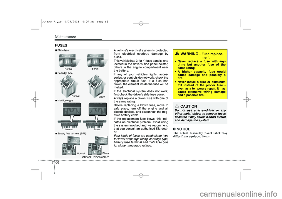
Four kinds of fuses are used: blade typefor lower amperage rating, cartridge type, battery fuse terminal and multi fuse typefor higher amperage ratings.
✽✽ NOTICE
The actual fuse/relay panel label may
differ from equipped items.
WARNING - Fuse replace-
ment
• Never replace a fuse with any- thing but another fuse of the same rating.
A higher capacity fuse could cause damage and possibly a
fire.
Never install a wire or aluminum foil instead of the proper fuse -
even as a temporary repair. It may
cause extensive wiring damage
and a possible fire.
CAUTION
Do not use a screwdriver or any
other metal object to remove fusesbecause it may cause a short circuitand damage the system.
Normal
Normal
■
Blade type
■ Cartridge type
■ Multi fuse type Blown
Blown
Normal Blown
ORB072110/ODM072020
Normal
Blown
■
Battery fuse terminal (BFT)
JD RHD 7.QXP 4/29/2013 4:06 PM Page 66
Page 1128 of 1206

767
Maintenance
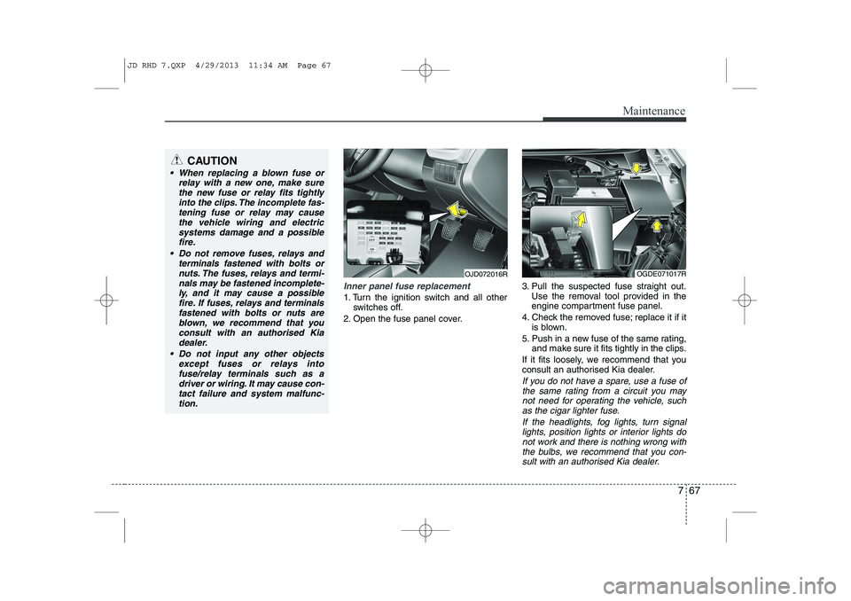
Inner panel fuse replacement
1. Turn the ignition switch and all otherswitches off.
2. Open the fuse panel cover. 3. Pull the suspected fuse straight out.
Use the removal tool provided in the
engine compartment fuse panel.
4. Check the removed fuse; replace it if it is blown.
5. Push in a new fuse of the same rating, and make sure it fits tightly in the clips.
If it fits loosely, we recommend that you
consult an authorised Kia dealer.
If you do not have a spare, use a fuse of the same rating from a circuit you may
not need for operating the vehicle, suchas the cigar lighter fuse.
If the headlights, fog lights, turn signallights, position lights or interior lights do not work and there is nothing wrong with
the bulbs, we recommend that you con- sult with an authorised Kia dealer.
OJD072016ROGDE071017R
CAUTION
When replacing a blown fuse or relay with a new one, make sure
the new fuse or relay fits tightlyinto the clips. The incomplete fas-tening fuse or relay may cause the vehicle wiring and electric
systems damage and a possiblefire.
Do not remove fuses, relays and terminals fastened with bolts or
nuts. The fuses, relays and termi-nals may be fastened incomplete-ly, and it may cause a possiblefire. If fuses, relays and terminals
fastened with bolts or nuts areblown, we recommend that youconsult with an authorised Kia
dealer.
Do not input any other objects except fuses or relays intofuse/relay terminals such as adriver or wiring. It may cause con-
tact failure and system malfunc-tion.
JD RHD 7.QXP 4/29/2013 11:34 AM Page 67
Page 1132 of 1206
771
Maintenance
Fuse/relay panel descriptionInner fuse panel
Inside the fuse/relay panel covers, you
can find the fuse/relay label describing
fuse/relay name and capacity.
✽✽NOTICE
Not all fuse panel descriptions in this
manual may be applicable to your vehi-cle. It is accurate at the time of printing.When you inspect the fuse panel in your
vehicle, refer to the fuse panel label.
✽
✽ NOTICE
The actual fuse/relay panel label may
differ from equipped items.
OJD072019R
OJD072020
JD RHD 7.QXP 4/29/2013 11:34 AM Page 71
Page 1133 of 1206

Maintenance
72
7
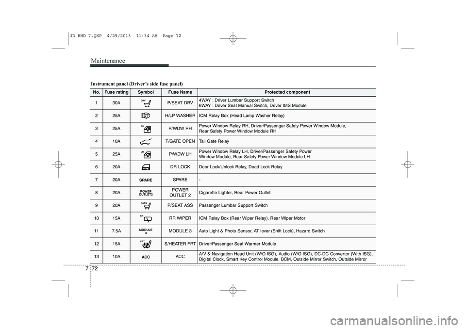
Instrument panel (Driver’s side fuse panel)
No.Fuse ratingSymbolFuse NameProtected component
130ADRVP/SEAT DRV4WAY : Driver Lumbar Support Switch
6WAY : Driver Seat Manual Switch, Driver IMS Module
225AH/LP WASHERICM Relay Box (Head Lamp Washer Relay)
325ARHP/WDW RHPower Window Relay RH, Driver/Passenger Safety Power Window Module,
Rear Safety Power Window Module RH
410AT/GATE OPENTail Gate Relay
525ALHP/WDW LHPower Window Relay LH, Driver/Passenger Safety Power
Window Module, Rear Safety Power Window Module LH
620ADR LOCKDoor Lock/Unlock Relay, Dead Lock Relay
720ASPARESPARE-
820APOWER
OUTLET2POWER
OUTLET 2Cigarette Lighter, Rear Power Outlet
920APASSP/SEAT ASSPassenger Lumbar Support Switch
1015ARRRR WIPERICM Relay Box (Rear Wiper Relay), Rear Wiper Motor
117.5AMODULE 3MODULE 3Auto Light & Photo Sensor, AT lever (Shift Lock), Hazard Switch
1215AFRTS/HEATER FRTDriver/Passenger Seat Warmer Module
1310AACCACCA/V & Navigation Head Unit (W/O ISG), Audio (W/O ISG), DC-DC Convertor (With ISG),
Digital Clock, Smart Key Control Module, BCM, Outside Mirror Switch, Outside Mirror
JD RHD 7.QXP 4/29/2013 11:34 AM Page 72