2014 JEEP PATRIOT ECU
[x] Cancel search: ECUPage 23 of 126

WARNING!
• Adjusting a seat while the vehicle is moving is dangerous. The suddenmovement of the seat could cause you to lose control. The seat belt might not
be properly adjusted, and you could be severely injured or killed. Only adjust a
seat while the vehicle is parked.
• Do not ride with the seatback reclined so that the seat belt is no longer resting
against your chest. In a collision, you could slide under the seat belt and be
severely injured or killed. Use the recliner only when the vehicle is parked.
REAR SEATS
Folding Rear Seatback
• To fold each rear seatback, pull the strap forward to move the seatback forwardand flat.
Reclining Rear Seatback
• To recline each rear seatback, pull thestrap forward just enough to release
the seatback latch. Then push the
seatback to a reclined position, ap-
proximately 35 degrees maximum,
and release the strap.
WARNING!
Be certain that the seatback is securely locked into position. If the seatback is not
securely locked into position, the seat will not provide the proper stability for child
seats and/or passengers. An improperly latched seat could cause serious injury.
Rear Seatback Pull Straps
GETTING STARTED
21
Page 34 of 126

POWER SUNROOF
The power sunroof switch is located on the overhead console.
Opening Sunroof
Express Open
Press the switch rearward and release it within one-half second. The sunroof will fully
open and stop automatically.
Manual Open
Press and hold the switch rearward to open the sunroof. Any release of the switch will
stop the movement, and the sunroof will remain in a partially open position until the
switch is pressed again.
Venting Sunroof
Press and release the button and the sunroof will open to the vent position.
This is called “Express Vent” and will occur regardless of sunroof position. During
Express Vent operation, any movement of the switch will stop the sunroof.
Closing Sunroof
Express Closing
Press the switch forward and release it within one-half second. The sunroof will fully
close automatically from any position.
Manual Closing
Press and hold the switch forward to close the sunroof. Any release of the switch will
stop the movement, and the sunroof will remain in a partially closed position until the
switch is pressed again.
Pinch Protection Feature
This feature will detect an obstruction in the opening of the sunroof during Express
Close operation. If an obstruction in the path of the sunroof is detected, the sunroof
will automatically retract. Remove the obstruction if this occurs. Next, press the
switch forward and release to Express Close.
NOTE:
If three consecutive sunroof close attempts result in Pinch Protect reversals, the
fourth close attempt will be a Manual Close movement with Pinch Protect disabled.
OPERATING YOUR VEHICLE
32
Page 35 of 126

WARNING!
• Never leave children alone in a vehicle, or with access to an unlocked vehicle.Never leave the Key Fob in or near the vehicle, or in a location accessible to
children. Occupants, particularly unattended children, can become entrapped
by the power sunroof while operating the power sunroof switch. Such entrap-
ment may result in serious injury or death.
• In a collision, there is a greater risk of being thrown from a vehicle with an open
sunroof. You could also be severely injured or killed. Always fasten your seat
belt properly and make sure all passengers are properly secured.
• Do not allow small children to operate the sunroof. Never allow your fingers,
other body parts, or any object to project through the sunroof opening. Injury
may result.
WIND BUFFETING
Wind buffeting can be described as a helicopter-type percussion sound. If buffeting
occurs with the rear windows open, adjust the front and rear windows together.
If buffeting occurs with the sunroof open, adjust the sunroof opening, or adjust any
window. This will minimize buffeting.
OPERATING YOUR VEHICLE
33
Page 71 of 126

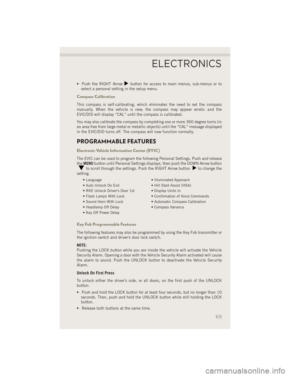
• Push the RIGHT Arrowbutton for access to main menus, sub-menus or to
select a personal setting in the setup menu.
Compass Calibration
This compass is self-calibrating, which eliminates the need to set the compass
manually. When the vehicle is new, the compass may appear erratic and the
EVIC/DID will display “CAL” until the compass is calibrated.
You may also calibrate the compass by completing one or more 360 degree turns (in
an area free from large metal or metallic objects) until the “CAL” message displayed
in the EVIC/DID turns off. The compass will now function normally.
PROGRAMMABLE FEATURES
Electronic Vehicle Information Center (EVIC)
The EVIC can be used to program the following Personal Settings. Push and release
the MENU button until Personal Settings displays, then push the DOWN Arrow button
to scroll through the settings. Push the RIGHT Arrow buttonto change the
setting.
• Language • Illuminated Approach
• Auto Unlock On Exit • Hill Start Assist (HSA)
• RKE Unlock Driver's Door 1st • Display Units In
• Flash Lamps With Lock • Confirmation of Voice Commands
• Sound Horn With Lock • Automatic Compass Calibration
• Headlamp Off Delay • Compass Variance
• Key Off Power Delay
Key Fob Programmable Features
The following features may also be programmed by using the Key Fob transmitter or
the ignition switch and driver's door lock switch.
NOTE:
Pushing the LOCK button while you are inside the vehicle will activate the Vehicle
Security Alarm. Opening a door with the Vehicle Security Alarm activated will cause
the alarm to sound. Push the UNLOCK button to deactivate the Vehicle Security
Alarm.
Unlock On First Press
To unlock either the driver's side, or all doors, on the first push of the UNLOCK
button:
• Push and hold the LOCK button for at least four seconds, but no longer than 10 seconds. Then, push and hold the UNLOCK button while still holding the LOCK
button.
• Release both buttons at the same time.
ELECTRONICS
69
Page 73 of 126

UNIVERSAL GARAGE DOOR OPENER (HomeLink®)
HomeLink®replaces up to three hand-held transmitters that operate devices such as
garage door openers, motorized gates, lighting or home security systems. The
HomeLink
®unit is powered by your vehicles 12 Volt battery.
The HomeLink
®buttons that are located in the overhead console or sunvisor
designate the three different HomeLink®channels.
The HomeLink
®indicator is located above the center button.
Before You Begin Programming
HomeLink®
Ensure that your vehicle is parked out-
side of the garage before you begin pro-
gramming.
For efficient programming and accurate
transmission of the radio-frequency sig-
nal, it is recommended that a new battery
be placed in the hand-held transmitter of
the device that is being programmed to
the HomeLink
®system.
Erase all channels before you begin programming. To erase the channels, place the
ignition switch into the ON/RUN position, then press and hold the two outside
HomeLink
®buttons (I and III) for up to 20 seconds or until the red indicator flashes.
NOTE:
Erasing all channels should only be performed when programming HomeLink
®for
the first time. Do not erase channels when programming additional buttons.
If you have any problems, or require assistance, please call toll-free
1-800-355-3515 or, on the Internet at www.HomeLink.com for information or
assistance.
ELECTRONICS
71
Page 75 of 126

Programming A Non-Rolling Code
NOTE:
For programming Garage Door Openers manufactured before 1995.
1. Turn the ignition switch to the ON/RUN position.
2. Place the hand-held transmitter 1 to 3 inches (3 to 8 cm) away from theHomeLink
®button you wish to program while keeping the HomeLink®indicator
light in view.
3. Simultaneously press and hold both the HomeLink
®button you want to program
and the hand-held transmitter button.
4. Continue to hold both buttons and observe the indicator light. The HomeLink
®
indicator will flash slowly and then rapidly after HomeLink®has received the
frequency signal from the hand-held transmitter. Release both buttons after the
indicator light changes from slow to rapid.
5. Press and hold the programmed HomeLink
®button and observe the indicator
light. If the indicator light stays on constantly, programming is complete and the
garage door (or device) should activate when the HomeLink
®button is pressed.
6. To program the two remaining HomeLink
®buttons, repeat each step for each
remaining button. DO NOT erase the channels.
Using HomeLink®
To operate, push and release the programmed HomeLink®button. Activation will now
occur for the programmed device (e.g., garage door opener, gate operator, security
system, entry door lock, home/office lighting, etc.,). The hand-held transmitter of the
device may also be used at any time.
WARNING!
• Your motorized door or gate will open and close while you are programming the universal transceiver. Do not program the transceiver if people or pets are in the
path of the door or gate.
• Do not run your vehicle in a closed garage or confined area while programming
the transceiver. Exhaust gas from your vehicle contains Carbon Monoxide (CO)
which is odorless and colorless. Carbon Monoxide is poisonous when inhaled
and can cause you and others to be severely injured or killed.
ELECTRONICS
73
Page 78 of 126

FOUR-WHEEL DRIVE OPERATION
This vehicle has two full time, on-demand, four-wheel-drive (4WD) systems avail-
able, Freedom Drive I™ and Freedom-Drive II™. They provide for all-weather,
all-terrain capability for added driving security in less-than-ideal road conditions.
Freedom-Drive I™ Four Wheel Drive System
• The vehicle will constantly monitor wheel slippage and transfer power to the axlethat can use it the most.
• For additional traction in sand, deep snow or loose traction surfaces, the “4WD Lock” sends equal amounts of the torque to the front and rear axles at low speeds.
• To activate, pull the T-handle, located in between the front driver and passenger seats, up once and release. The “4WD Indicator Light” will come on in the cluster.
Freedom-Drive I™ Components
1 — Rear Differential
2 — Electronically Controlled Coupling
3 — Driveshaft
4 — Power Transfer Unit
OFF-ROAD CAPABILITIES
76
Page 91 of 126

NOTE:• There are front and rear jacking locations on each side of the body. The frontlocations are outlined by two triangular cutouts, the rear locations by two
rectangular cutouts.
• For vehicles equipped with plastic trim, the plastic has been cut away
to expose the jacking locations in
the body.
• Do not raise the vehicle until you are sure the jack is securely engaged.
3. Turn the jack screw to the left until the jack can be placed under the jacking
location. Once the jack is positioned,
turn the jack screw to the right until
the jack head is properly engaged with
the lift area closest to the wheel to be
changed.
4. Using the swivel wrench raise the ve- hicle by turning the jack screw to the
right. Raise the vehicle only until the
tire just clears the surface and enough
clearance is obtained to install the
spare tire. Minimum tire lift provides
maximum stability.
Front Jack Engaged
Rear Jack Engaged
WHAT TO DO IN EMERGENCIES
89