Page 14 of 118
4. High Beam IndicatorIndicates that headlights are on high beam.
5. Front Fog Light Indicator — If Equipped This indicator will illuminate when the front fog
lights are on.
6. Selectable EVIC Information
This area of the cluster will display selectable information
(such as compass, outside temperature etc.). For further
information, refer to “Electronic Vehicle Information Cen-
ter (EVIC) — If Equipped” in your Owner Manual on the
DVD.
7. Turn Signal Indicator
The arrows will flash with the exterior turn sig-
nals when the turn signal lever is operated. A tone
will chime, and an EVIC message will appear if either
turn signal is left on for more than 1 mile (1.6 km). NOTE:
If either indicator flashes at a rapid rate, check
for a defective outside light bulb.
8. Speedometer
Indicates vehicle speed.
9. Selectable EVIC Information
This area of the cluster will display selectable informa-
tion (such as compass, outside temperature etc.). For
further information, refer to “Electronic Vehicle Informa-
tion Center (EVIC) — If Equipped” in your Owner
Manual on the DVD.
10. Malfunction Indicator Light (MIL)
The Malfunction Indicator Light (MIL) is part of
an Onboard Diagnostic System called OBD II that
monitors engine and automatic transmission con-
trol systems. The light will illuminate when the key is in
12 UNDERSTANDING YOUR INSTRUMENT PANEL
Page 23 of 118
•The ESC system will make buzzing or clicking
sounds when it is active. This is normal; the sounds
will stop when ESC becomes inactive following the
maneuver that caused the ESC activation.
22. Park/Headlight ON Indicator — If Equipped
This indicator will illuminate when the park
lights or headlights are turned on.
ELECTRONIC VEHICLE INFORMATION CENTER
(EVIC)
The Electronic Vehicle Information Center (EVIC) fea-
tures a driver-interactive display that is located in the
instrument cluster. This system conveniently allows the driver to select a
variety of useful information by pressing the switches
mounted on the steering wheel.
Refer to “Electronic Vehicle Information Center –
If Equipped” in the Owner’s Manual for further infor-
mation.Electronic Vehicle Information Center (EVIC)
3
UNDERSTANDING YOUR INSTRUMENT PANEL 21
Page 39 of 118
•A 12 Volt heater built into the fuel filter housing aids in
preventing fuel gelling. It is controlled by a built-in
thermostat.
• A Diesel Pre-Heat system both improves engine start-
ing and reduces the amount of white smoke generated
by a warming engine.
Normal Starting Procedure — Keyless
Enter-N-Go™
Observe the instrument panel cluster lights when starting
the engine.
NOTE: Normal starting of either a cold or a warm
engine is obtained without pumping or pressing the
accelerator pedal
1. Always apply the parking brake.
2. For vehicles equipped with an automatic transmis- sion, place the shift lever into the PARK position. 3. Press and hold the brake pedal while pressing the
ENGINE START/STOP button once.
NOTE: A delay of the start of up to five seconds is
possible under very cold conditions. The �Wait to Start�
telltale will be illuminated during the pre-heat process
and the start will commence upon the telltale going out.
CAUTION!
If the “Water in Fuel Indicator Light” remains on, DO
NOT START the engine before you drain the water
from the fuel filters to avoid engine damage. Refer to
“Maintenance Procedures/Draining Fuel/Water Sepa-
rator Filter” in “Maintaining Your Vehicle” for fur-
ther information.
4. The system will take over and attempt to start the vehicle. If the vehicle fails to start, the starter will
disengage automatically after 30 seconds.
4
STARTING AND OPERATING 37
Page 41 of 118
NORMAL OPERATION
Observe the following when the diesel engine is operat-
ing.
•All message center lights are off.
• Malfunction Indicator Light (MIL) is off.
• Engine Oil Pressure telltale is not illuminated.
• Voltmeter operation:
The voltmeter may show a gauge fluctuation at various
engine temperatures. This is caused by the glow plug
heating system. The number of cycles and the length of
the cycling operation is controlled by the engine control
module. Glow plug heater operation can run for several
minutes, once the heater operation is complete the volt-
meter needle will stabilize.
Cold Weather Precautions
Operation in ambient temperature below 32°F (0°C) may
require special considerations. The following charts sug-
gest these options:
Fuel Operating Range
NOTE: Use “Ultra Low Sulfur Diesel Fuels” ONLY.
*No. 1 Ultra Low Sulfur Diesel Fuel should only be used
where extended arctic conditions (-10°F/-23°C) exist.
Fuel Operating Range Chart
4
STARTING AND OPERATING 39
Page 61 of 118
Towing Requirements — Trailer Lights And Wiring
Whenever you pull a trailer, regardless of the trailer size,
stoplights and turn signals on the trailer are required for
motoring safety.
The Trailer Tow Package may include a four- and seven-
pin wiring harness. Use a factory approved trailer har-
ness and connector.
NOTE:Do not cut or splice wiring into the vehicles
wiring harness.
The electrical connections are all complete to the vehicle
but you must mate the harness to a trailer connector.
Refer to the following illustrations.
Four-Pin Connector
1 — Female Pins 4 — Park
2 — Male Pin 5 — Left Stop/Turn
3 — Ground 6 — Right Stop/Turn
4
STARTING AND OPERATING 59
Page 103 of 118
Once A Month Or Before A Long Trip:
•Check engine oil level
• Check windshield washer fluid level
• Check the tire inflation pressures and look for unusual
wear or damage
• Check the fluid levels of the coolant reservoir, brake
master cylinder, power steering and transmission as
needed
• Check function of all interior and exterior lights
Required Maintenance
Refer to the Maintenance Schedules on the following
pages for required maintenance.At Every Oil Change Interval As Indicated By Oil Change Indicator System:
•Change oil and filter.
• Completely fill the Diesel Exhaust Fluid tank.
• Rotate the tires. Rotate at the first sign of irregu-
lar wear, even if it occurs before the oil indicator
system turns on.
• Inspect battery and clean and tighten terminals as
required.
• Inspect automatic transmission fluid if equipped
with dipstick.
• Inspect brake pads, shoes, rotors, drums, hoses
and park brake.
•
Inspect engine cooling system protection and hoses.
• Inspect exhaust system.
• Inspect engine air cleaner if using in dusty or
off-road conditions.
6
MAINTENANCE SCHEDULE 101
Page 107 of 118
Once A Month Or Before A Long Trip:
•Check engine oil level
• Check windshield washer fluid level
• Check the tire inflation pressures and look for unusual
wear or damage
• Check the fluid levels of the coolant reservoir, brake
master cylinder, power steering and transmission as
needed
• Check function of all interior and exterior lights
Required Maintenance
Refer to the Maintenance Schedules on the following
pages for required maintenance.At Every Oil Change Interval As Indicated By Oil Change Indicator System:
•Change oil and filter.
• Completely fill the Diesel Exhaust Fluid tank.
• Rotate the tires. Rotate at the first sign of irregu-
lar wear, even if it occurs before the oil indicator
system turns on.
• Inspect battery and clean and tighten terminals as
required.
• Inspect automatic transmission fluid if equipped
with dipstick.
• Inspect brake pads, shoes, rotors, drums, hoses
and park brake.
•
Inspect engine cooling system protection and hoses.
• Inspect exhaust system.
• Inspect engine air cleaner if using in dusty or
off-road conditions.
6
MAINTENANCE SCHEDULE 105
Page 113 of 118
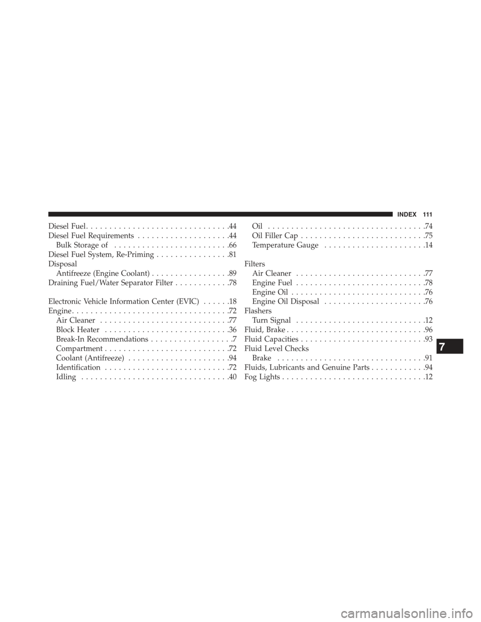
Diesel Fuel...............................44
Diesel Fuel Requirements ....................44
Bulk Storage of .........................66
Diesel Fuel System, Re-Priming ................81
Disposal Antifreeze (Engine Coolant) .................89
Draining Fuel/Water Separator Filter ............78
Electronic Vehicle Information Center (EVIC) ......18
Engine ..................................72
Air Cleaner ............................77
Block Heater ...........................36
Break-In Recommendations ..................7
Compartment ...........................72
Coolant (Antifreeze) ......................94
Identification ...........................72
Idling ................................40 Oil ..................................74
Oil Filler Cap
...........................75
Temperature Gauge ......................14
Filters Air Cleaner ............................77
Engine Fuel ............................78
Engine Oil .............................76
Engine Oil Disposal ......................76
Flashers Turn Signal ............................12
Fluid, Brake ..............................96
Fluid Capacities ...........................93
Fluid Level Checks Brake ................................91
Fluids, Lubricants and Genuine Parts ............94
Fog Lights ...............................12
7
INDEX 111