Page 39 of 118
•A 12 Volt heater built into the fuel filter housing aids in
preventing fuel gelling. It is controlled by a built-in
thermostat.
• A Diesel Pre-Heat system both improves engine start-
ing and reduces the amount of white smoke generated
by a warming engine.
Normal Starting Procedure — Keyless
Enter-N-Go™
Observe the instrument panel cluster lights when starting
the engine.
NOTE: Normal starting of either a cold or a warm
engine is obtained without pumping or pressing the
accelerator pedal
1. Always apply the parking brake.
2. For vehicles equipped with an automatic transmis- sion, place the shift lever into the PARK position. 3. Press and hold the brake pedal while pressing the
ENGINE START/STOP button once.
NOTE: A delay of the start of up to five seconds is
possible under very cold conditions. The �Wait to Start�
telltale will be illuminated during the pre-heat process
and the start will commence upon the telltale going out.
CAUTION!
If the “Water in Fuel Indicator Light” remains on, DO
NOT START the engine before you drain the water
from the fuel filters to avoid engine damage. Refer to
“Maintenance Procedures/Draining Fuel/Water Sepa-
rator Filter” in “Maintaining Your Vehicle” for fur-
ther information.
4. The system will take over and attempt to start the vehicle. If the vehicle fails to start, the starter will
disengage automatically after 30 seconds.
4
STARTING AND OPERATING 37
Page 40 of 118
5. If you wish to stop the cranking of the engine prior tothe engine starting, press the button again.
6. Check that the oil pressure warning light has turned off.
7. Release the parking brake.
Starting Fluids
The engine is equipped with a glow plug preheating
system. If the instructions in this manual are followed,
the engine should start in all conditions and no type of
starting fluid should be used.
WARNING!
• Do not leave children or animals inside parked
vehicles in hot weather. Interior heat build up may
cause serious injury or death.
(Continued)
WARNING! (Continued)
•When leaving the vehicle, always remove the key
fob and lock your vehicle.
• Never leave children alone in a vehicle, or with
access to an unlocked vehicle. Allowing children to
be in a vehicle unattended is dangerous for a
number of reasons. A child or others could be
seriously or fatally injured. Children should be
warned not to touch the parking brake, brake pedal
or the shift lever. Do not leave the key fob in or
near the vehicle (or in a location accessible to
children), and do not leave the ignition of a vehicle
equipped with Keyless Enter-N-Go™ in the ACC
or ON/RUN mode. A child could operate power
windows, other controls, or move the vehicle.
38 STARTING AND OPERATING
Page 54 of 118
WARNING!
•An improperly adjusted Weight Distributing Hitch
system may reduce handling, stability, braking
performance, and could result in a collision.
•
Weight Distributing Systems may not be compatible
with Surge Brake Couplers. Consult with your hitch
and trailer manufacturer or a reputable Recreational
Vehicle dealer for additional information.
Trailer Hitch Classification
The following chart provides the industry standard for
the maximum trailer weight a given trailer hitch class can
tow and should be used to assist you in selecting the
correct trailer hitch for your intended towing condition.
Trailer Hitch Classification Definitions
Class Max. Trailer Hitch
Industry Standards
Class I - Light Duty 2,000 lbs (907 kg)
Class II - Medium Duty 3,500 lbs (1 587 kg) Class III - Heavy Duty 5,000 lbs (2 268 kg)
Class IV - Extra Heavy Duty 10,000 lbs (4 540 kg)
Refer to the “Trailer Towing Weights (Maximum
Trailer Weight Ratings)” chart for the Maximum
Gross Trailer Weight (GTW) towable for your given
drivetrain.
All trailer hitches should be professionally installed
on your vehicle.
52 STARTING AND OPERATING
Page 93 of 118
Brake System
Brake Master Cylinder — Brake Fluid Level Check
The fluid level of the master cylinder should be checked
when performing under the hood service, or immedi-
ately if the “Brake System Warning Light” indicates
system failure.
The brake master cylinder has a translucent plastic
reservoir. On the outboard side of the reservoir, there is a
“MAX” mark and a “MIN” mark. The fluid level must be
kept within these two marks. Do not add fluid above the
full mark because leakage may occur at the cap.
With disc brakes, the fluid level can be expected to fall as
the brake linings wear. However, an unexpected drop in
fluid level may be caused by a leak and a system check
should be conducted.Refer to “Fluids, Lubricants, and Genuine Parts” in
“Maintaining Your Vehicle” for further information.WARNING!
•
Use only manufacturer’s recommended brake
fluid. Refer to “Fluids, Lubricants, and Genuine
Parts” in “Maintaining Your Vehicle” for further
information. Using the wrong type of brake fluid
can severely damage your brake system and/or
impair its performance. The proper type of brake
fluid for your vehicle is also identified on the
original factory installed hydraulic master cylinder
reservoir.
(Continued)
5
MAINTAINING YOUR VEHICLE 91
Page 103 of 118
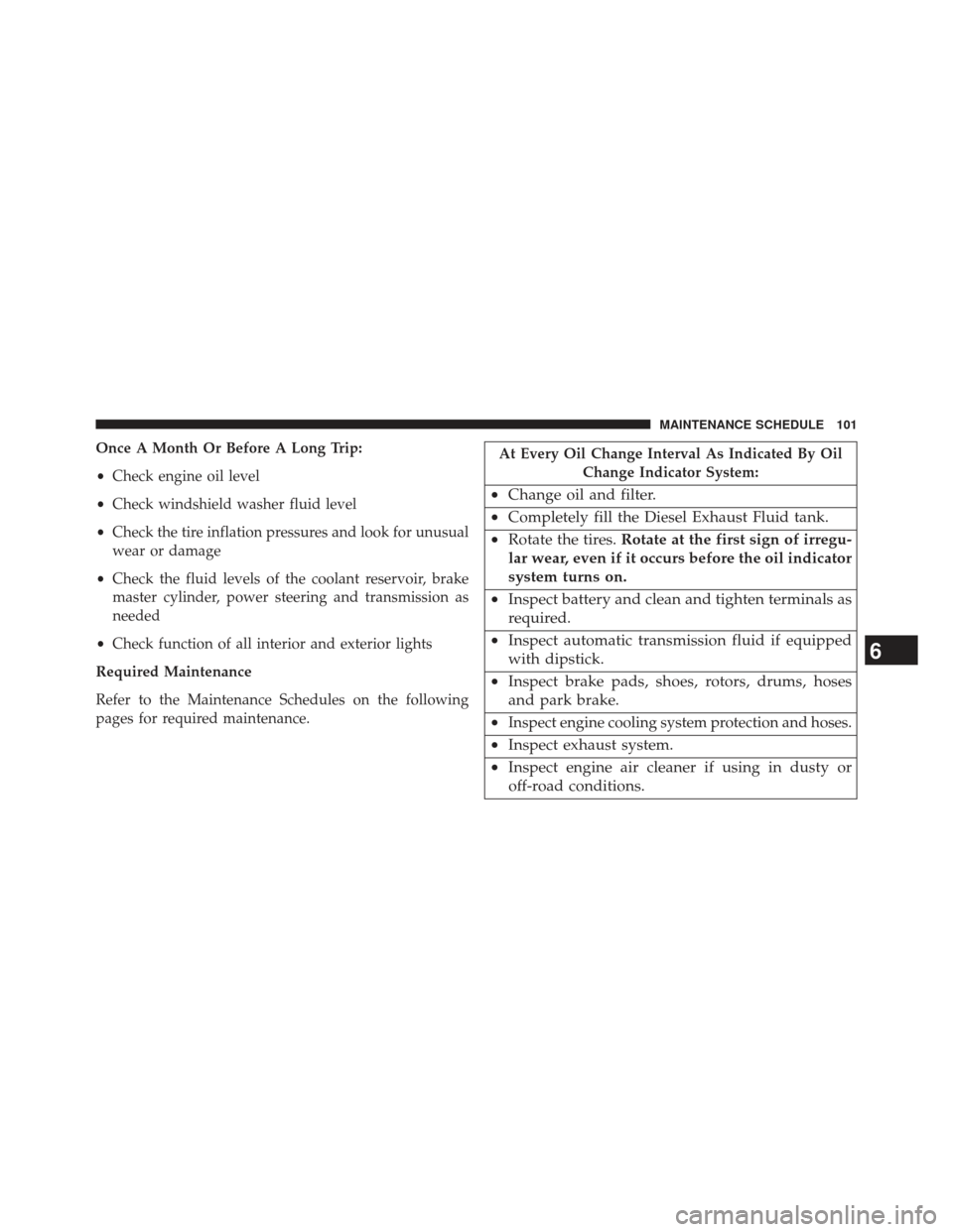
Once A Month Or Before A Long Trip:
•Check engine oil level
• Check windshield washer fluid level
• Check the tire inflation pressures and look for unusual
wear or damage
• Check the fluid levels of the coolant reservoir, brake
master cylinder, power steering and transmission as
needed
• Check function of all interior and exterior lights
Required Maintenance
Refer to the Maintenance Schedules on the following
pages for required maintenance.At Every Oil Change Interval As Indicated By Oil Change Indicator System:
•Change oil and filter.
• Completely fill the Diesel Exhaust Fluid tank.
• Rotate the tires. Rotate at the first sign of irregu-
lar wear, even if it occurs before the oil indicator
system turns on.
• Inspect battery and clean and tighten terminals as
required.
• Inspect automatic transmission fluid if equipped
with dipstick.
• Inspect brake pads, shoes, rotors, drums, hoses
and park brake.
•
Inspect engine cooling system protection and hoses.
• Inspect exhaust system.
• Inspect engine air cleaner if using in dusty or
off-road conditions.
6
MAINTENANCE SCHEDULE 101
Page 107 of 118
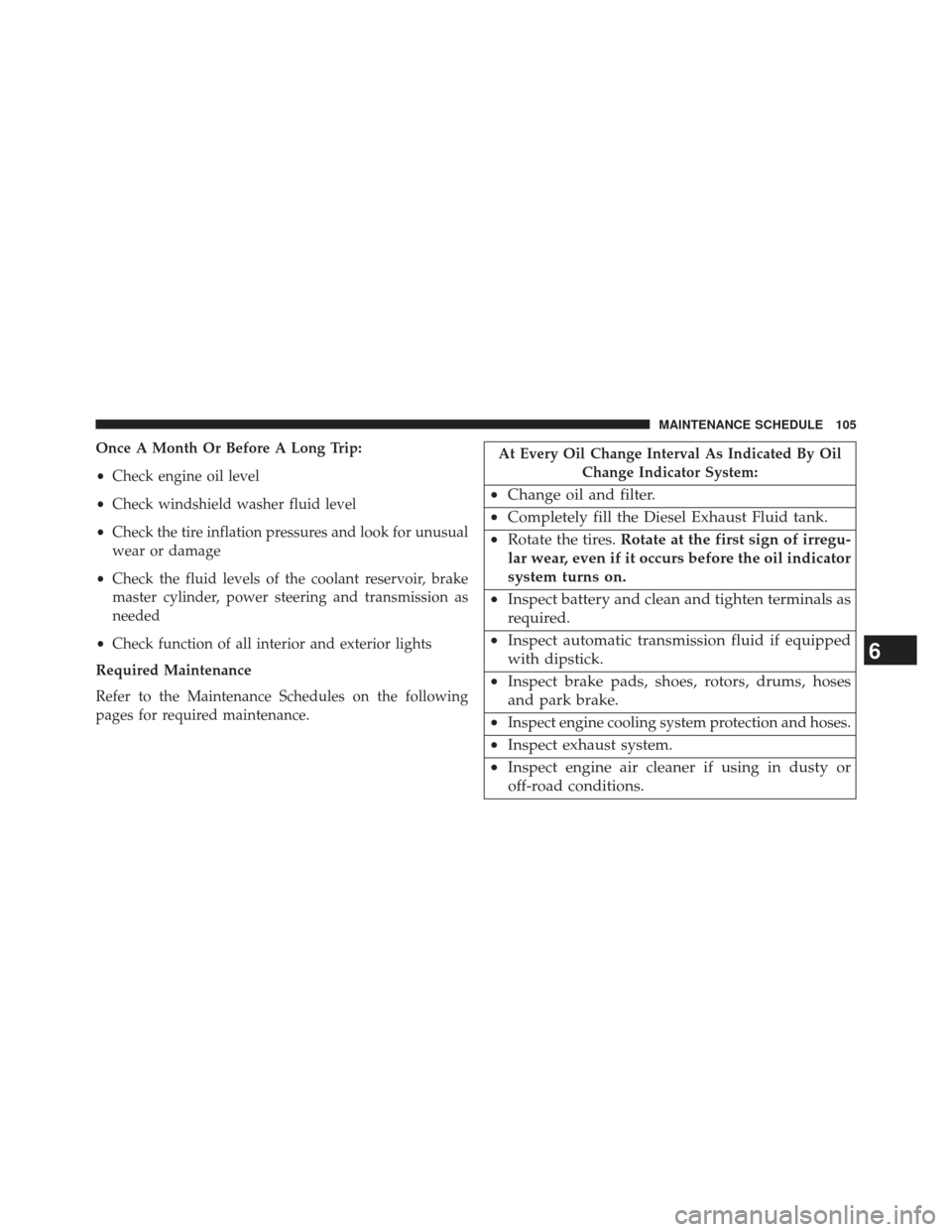
Once A Month Or Before A Long Trip:
•Check engine oil level
• Check windshield washer fluid level
• Check the tire inflation pressures and look for unusual
wear or damage
• Check the fluid levels of the coolant reservoir, brake
master cylinder, power steering and transmission as
needed
• Check function of all interior and exterior lights
Required Maintenance
Refer to the Maintenance Schedules on the following
pages for required maintenance.At Every Oil Change Interval As Indicated By Oil Change Indicator System:
•Change oil and filter.
• Completely fill the Diesel Exhaust Fluid tank.
• Rotate the tires. Rotate at the first sign of irregu-
lar wear, even if it occurs before the oil indicator
system turns on.
• Inspect battery and clean and tighten terminals as
required.
• Inspect automatic transmission fluid if equipped
with dipstick.
• Inspect brake pads, shoes, rotors, drums, hoses
and park brake.
•
Inspect engine cooling system protection and hoses.
• Inspect exhaust system.
• Inspect engine air cleaner if using in dusty or
off-road conditions.
6
MAINTENANCE SCHEDULE 105
Page 112 of 118
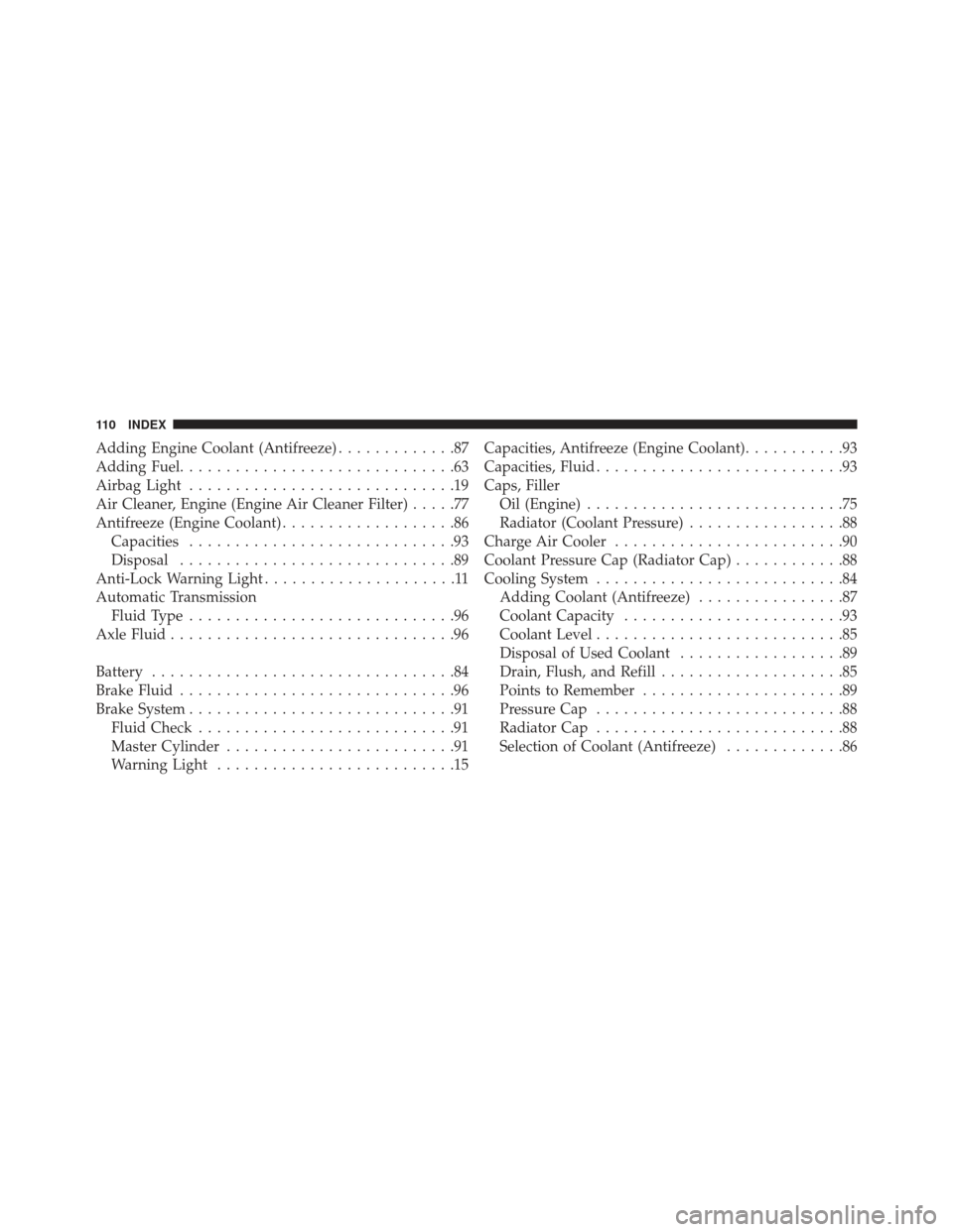
Adding Engine Coolant (Antifreeze).............87
Adding Fuel ..............................63
Airbag Light .............................19
Air Cleaner, Engine (Engine Air Cleaner Filter) .....77
Antifreeze (Engine Coolant) ...................86
Capacities .............................93
Disposal ..............................89
Anti-Lock Warning Light .....................11
Automatic Transmission Fluid Type .............................96
Axle Fluid ...............................96
Battery .................................84
Brake Fluid ..............................96
Brake System .............................91
Fluid Check ............................91
Master Cylinder .........................91
Warning Light ..........................15 Capacities, Antifreeze (Engine Coolant)
...........93
Capacities, Fluid ...........................93
Caps, Filler Oil (Engine) ............................75
Radiator (Coolant Pressure) .................88
Charge Air Cooler .........................90
Coolant Pressure Cap (Radiator Cap) ............88
Cooling System ...........................84
Adding Coolant (Antifreeze) ................87
Coolant Capacity ........................93
Coolant Level ...........................85
Disposal of Used Coolant ..................89
Drain, Flush, and Refill ....................85
Points to Remember ......................89
Pressure Cap ...........................88
Radiator Cap ...........................88
Selection of Coolant (Antifreeze) .............86
110 INDEX
Page 113 of 118
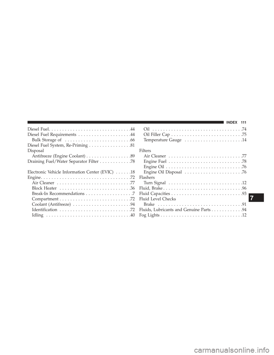
Diesel Fuel...............................44
Diesel Fuel Requirements ....................44
Bulk Storage of .........................66
Diesel Fuel System, Re-Priming ................81
Disposal Antifreeze (Engine Coolant) .................89
Draining Fuel/Water Separator Filter ............78
Electronic Vehicle Information Center (EVIC) ......18
Engine ..................................72
Air Cleaner ............................77
Block Heater ...........................36
Break-In Recommendations ..................7
Compartment ...........................72
Coolant (Antifreeze) ......................94
Identification ...........................72
Idling ................................40 Oil ..................................74
Oil Filler Cap
...........................75
Temperature Gauge ......................14
Filters Air Cleaner ............................77
Engine Fuel ............................78
Engine Oil .............................76
Engine Oil Disposal ......................76
Flashers Turn Signal ............................12
Fluid, Brake ..............................96
Fluid Capacities ...........................93
Fluid Level Checks Brake ................................91
Fluids, Lubricants and Genuine Parts ............94
Fog Lights ...............................12
7
INDEX 111