2014 JEEP COMPASS wheel
[x] Cancel search: wheelPage 71 of 124

Bluetooth® STREAMING AUDIO
If equipped with Uconnect®Voice Command, your Bluetooth®-equipped iPod®
devices, cell phones or other media players, may also be able to stream music to your
vehicle's speakers. Your connected device must be Bluetooth®-compatible, and
paired with your radio (see Uconnect®Phone for pairing instructions).
• Non-Touchscreen Radios:
Press the
“AUX” button on the radio faceplate
until “BT” or “Audio Streaming” is dis-
played on the radio screen.
• Touchscreen-Radios: Press the RADIO/
MEDIA or MEDIA hard-key and then
touch the “AUX” soft-key tab.
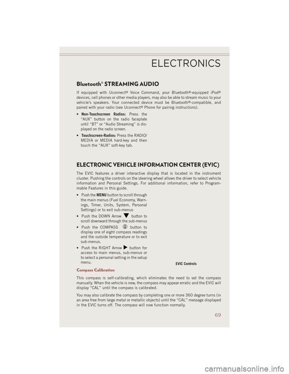
ELECTRONIC VEHICLE INFORMATION CENTER (EVIC)
The EVIC features a driver interactive display that is located in the instrument
cluster. Pushing the controls on the steering wheel allows the driver to select vehicle
information and Personal Settings. For additional information, refer to Program-
mable Features in this guide.
•
Push theMENU button to scroll through
the main menus (Fuel Economy, Warn-
ings, Timer, Units, System, Personal
Settings) or to exit sub-menus
• Push the DOWN Arrow
button to
scroll downward through the sub-menus
• Push the COMPASSbutton to
display one of eight compass readings
and the outside temperature or to exit
sub-menus.
• Push the RIGHT Arrow
button for
access to main menus, sub-menus or
to select a personal setting in the setup
menu.
Compass Calibration
This compass is self-calibrating, which eliminates the need to set the compass
manually. When the vehicle is new, the compass may appear erratic and the EVIC will
display “CAL” until the compass is calibrated.
You may also calibrate the compass by completing one or more 360 degree turns (in
an area free from large metal or metallic objects) until the “CAL” message displayed
in the EVIC turns off. The compass will now function normally.
EVIC Controls
ELECTRONICS
69
Page 78 of 124

FOUR-WHEEL DRIVE OPERATION
This vehicle has two full time, on-demand, four-wheel-drive (4WD) systems avail-
able, Freedom Drive I™ and Freedom-Drive II™. They provide for all-weather,
all-terrain capability for added driving security in less-than-ideal road conditions.
Freedom-Drive I™ Four Wheel Drive System
• The vehicle will constantly monitor wheel slippage and transfer power to the axlethat can use it the most.
• For additional traction in sand, deep snow or loose traction surfaces, the “4WD Lock” sends equal amounts of the torque to the front and rear axles at low speeds.
• To activate, pull the T-handle, located in between the front driver and passenger seats, up once and release. The “4WD Indicator Light” will come on in the cluster.
Freedom-Drive I™ Components
1 — Rear Differential
2 — Electronically Controlled Coupling
3 — Driveshaft
4 — Power Transfer Unit
OFF-ROAD CAPABILITIES
76
Page 79 of 124

• This can be done on the fly, at any vehicle speed. To deactivate, simply pull on theT-handle one more time. The “4WD Indicator Light” will then turn off.
Trail Rated® Freedom-Drive II™ Four Wheel Drive System (IF EQUIPPED)
This system offers all the benefits of Freedom Drive I™ plus the
rugged capability of true Trail-Rated off road performance with three
additional features:
Off-Road Mode
Pulling up on the T-handle while the gear shift lever is in the Low
position activates the Off-Road mode.
This feature allows power to be sent to all four wheels when additional traction is
required while also delivering enhanced off-road capability for water fording, moving
on steep grades and rock crawling.
Brake Lock Differential
This feature helps keep the vehicle moving forward when one wheel loses traction by
directing power from the wheel that slips to the wheel with more grip on the same axle
providing more traction in off-road situations.
Hill Descent Control/Hill Start Assist
The Hill Descent Control System maintains vehicle speed while descending hills
during off-road driving situations and is available in both low and reverse gears.
This allows a smooth and controlled hill descent on rough or slippery terrain without
the driver needing to touch the brake pedal.
The Hill Start Assist system assists the driver when starting a vehicle from a stop on
a hill.
4WD T-Handle
OFF-ROAD CAPABILITIES
77
Page 81 of 124

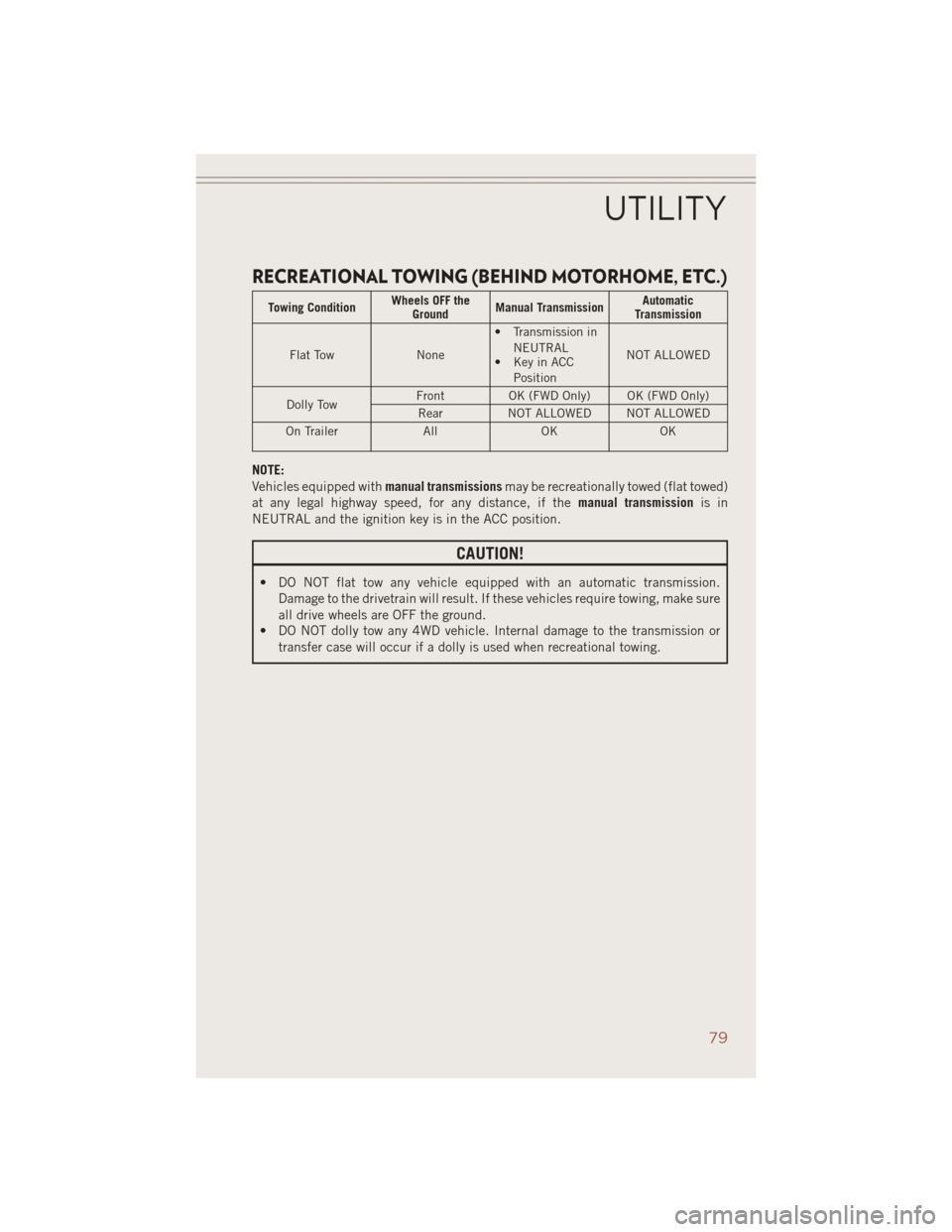
RECREATIONAL TOWING (BEHIND MOTORHOME, ETC.)
Towing ConditionWheels OFF the
Ground Manual Transmission Automatic
Transmission
Flat Tow None• Transmission in
NEUTRAL
• Key in ACC
Position NOT ALLOWED
Dolly Tow Front
OK (FWD Only) OK (FWD Only)
Rear NOT ALLOWED NOT ALLOWED
On Trailer AllOK OK
NOTE:
Vehicles equipped with manual transmissionsmay be recreationally towed (flat towed)
at any legal highway speed, for any distance, if the manual transmissionis in
NEUTRAL and the ignition key is in the ACC position.
CAUTION!
• DO NOT flat tow any vehicle equipped with an automatic transmission. Damage to the drivetrain will result. If these vehicles require towing, make sure
all drive wheels are OFF the ground.
• DO NOT dolly tow any 4WD vehicle. Internal damage to the transmission or
transfer case will occur if a dolly is used when recreational towing.
UTILITY
79
Page 83 of 124

IF THE LIGHT STARTS FLASHING INDICATING A LOW TIRE PRESSURE, ADJUST THE AIR
PRESSURE IN THE LOW TIRE TO THE AIR PRESSURE SHOWN ON THE VEHICLE PLACARD OR
TIRE INFLATION PRESSURE LABEL LOCATED ON THE DRIVER'S DOOR.
NOTE:
AFTER INFLATION, THE VEHICLE MAY NEED TO BE DRIVEN FOR 20 MINUTES
BEFORE THE FLASHING LIGHT WILL TURN OFF.
Please note that the TPMS is not a substitute for proper tire maintenance, and it is
the driver’s responsibility to maintain correct tire pressure, even if under-inflation
has not reached the level to trigger illumination of the TPMS low tire pressure telltale.
Your vehicle has also been equipped with a TPMS malfunction indicator to indicate
when the system is not operating properly. The TPMS malfunction indicator is
combined with the low tire pressure telltale.
When the system detects a malfunction, the telltale will flash for approximately one
minute and then remain continuously illuminated. This sequence will continue upon
subsequent vehicle start-ups as long as the malfunction exists. When the malfunc-
tion indicator is illuminated, the system may not be able to detect or signal low tire
pressure as intended. TPMS malfunctions may occur for a variety of reasons,
including the installation of replacement or alternate tires or wheels on the vehicle
that prevent the TPMS from functioning properly. Always check the TPMS malfunc-
tion telltale after replacing one or more tires or wheels on your vehicle to ensure that
the replacement or alternate tires and wheels allow the TPMS to continue to function
properly.
NOTE:
Tire pressures change by approximately 1 psi (7 kPa) per 12° F (7° C) of air
temperature change. Keep this in mind when checking tire pressure inside a garage,
especially in the Winter. Example: If garage temperature is 68°F (20°C) and the
outside temperature is 32°F (0°C), then the cold tire inflation pressure should be
increased by 3 psi (21 kPa), which equals 1 psi (7 kPa) for every 12°F (7°C) for this
outside temperature condition.
CAUTION!
The TPMS has been optimized for the original equipment tires and wheels. TPMS
pressures and warning have been established for the tire size equipped on your
vehicle. Undesirable system operation or sensor damage may result when using
replacement equipment that is not of the same size, type, and/or style. Aftermar-
ket wheels can cause sensor damage. Do not use tire sealant from a can, or
balance beads if your vehicle is equipped with a TPMS, as damage to the sensors
may result.
WHAT TO DO IN EMERGENCIES
81
Page 88 of 124

JACKING AND TIRE CHANGING
Jack Location
The jack and jack-handle are stowed under the load floor in the cargo area.
Spare Tire Stowage
The compact spare tire is stowed under
the rear load floor in the cargo area.
Spare Tire Removal
• Lift up the load floor cover and removethe hold down.
Preparations For Jacking
1. Park the vehicle on a firm level sur-
face, avoiding ice or slippery areas.
2. Turn on the Hazard Warning flasher.
3. Set the parking brake.
4. Place the shift lever in PARK (auto- matic transmission) or REVERSE
(manual transmission).
5. Turn OFF the ignition.
6. Block both the front and rear of the wheel diagonally opposite the jacking position. For example, if changing the right front tire, block the left rear wheel.
NOTE:
Passengers should not remain in the ve-
hicle while the vehicle is being jacked.
Spare/Jack/Tools
1 — Spare Tire
2 — Jack And Tools
Wheel Blocked
WHAT TO DO IN EMERGENCIES
86
Page 89 of 124

Jacking Instructions
NOTE:
Refer to “Tires — General Information”
in “Starting And Operating” in the Own-
er's Manual on the DVD for further infor-
mation about the spare tire, it's use, and
operation.
1.
Remove the scissors jack and lug
wrench from the spare wheel as an
assembly. Turn the jack screw to the
left to loosen the lug wrench and re-
move the wrench from the jack assem-
bly.
2. Loosen, but do not remove, the wheel nuts by turning them to the left one turnwhile the wheel is still on the ground.
NOTE: • There are front and rear jacking locations on each side of the body. The frontlocations are outlined by two triangular cutouts, the rear locations by two
rectangular cutouts.
Warning Label
Front Jack Engaged
WHAT TO DO IN EMERGENCIES
87
Page 90 of 124

• For vehicles equipped with plastic trim, the plastic has been cut away to exposethe jacking locations in the body.
• Do not raise the vehicle until you are sure the jack is securely engaged.
3. Turn the jack screw to the left until the jack can be placed under the jacking
location. Once the jack is positioned,
turn the jack screw to the right until
the jack head is properly engaged with
the lift area closest to the wheel to be
changed.
4. Using the swivel wrench raise the ve- hicle by turning the jack screw to the
right. Raise the vehicle only until the
tire just clears the surface and enough
clearance is obtained to install the
spare tire. Minimum tire lift provides
maximum stability.
5. Remove the wheel nuts and pull the wheel and wheel covers, where applicable, off the hub. Install the spare wheel and wheel nuts with the cone shaped end of the
nuts toward the wheel. Lightly tighten the nuts.
NOTE:
The wheel cover is held on the wheel by
the wheel nuts. When reinstalling the
original wheel, properly align the wheel
cover to the valve stem, place the wheel
cover onto the wheel, then install the
wheel nuts.
6. Lower the vehicle by turning the jack screw to the left.
7.
Finish tightening the nuts. Push down
on the wrench while at the end of the
handle for increased leverage. Tighten
the lug nuts in a star pattern until each
nut has been tightened twice. The cor-
rect wheel nut torque is 100 ft/lbs
(135 N·m). If you doubt that you have tightened the nuts correctly, have them
checked with a torque wrench by your authorized dealer or service station.
8. Remove the wheel blocks and lower the jack until it is free. Reassemble the lug wrench to the jack assembly and stow it in the spare tire area. Secure the
assembly using the means provided.
Rear Jack Engaged
Installing Spare
WHAT TO DO IN EMERGENCIES
88