Page 350 of 432
Maintenance
16 7
G060200AEN-EU
Changing the engine oil and filter
Have engine oil and filter changed by an
authorized HYUNDAI dealer according to
the Maintenance Schedule at the begin-
ning of this section.
CALIFORNIA PROPOSI-
TION 65 WARNING
Engine oil contains chemicals
known to the State of California to
cause cancer, birth defects and
reproductive harm. Used engine oil
may cause irritation or cancer of
the skin if left in contact with the
skin for prolonged periods of time.
Always protect your skin by wash-
ing your hands thoroughly with
soap and warm water as soon as
possible after handling used oil.
Page 354 of 432

Maintenance
20 7
BRAKE FLUID
G080100AEN
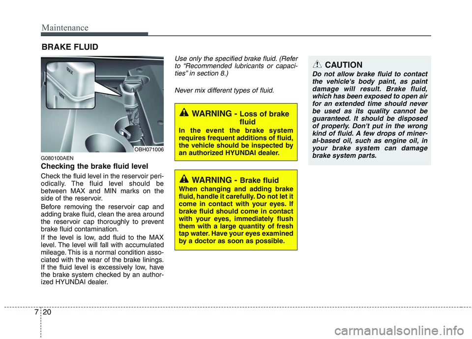
Checking the brake fluid level
Check the fluid level in the reservoir peri-
odically. The fluid level should be
between MAX and MIN marks on the
side of the reservoir.
Before removing the reservoir cap and
adding brake fluid, clean the area around
the reservoir cap thoroughly to prevent
brake fluid contamination.
If the level is low, add fluid to the MAX
level. The level will fall with accumulated
mileage. This is a normal condition asso-
ciated with the wear of the brake linings.
If the fluid level is excessively low, have
the brake system checked by an author-
ized HYUNDAI dealer.
Use only the specified brake fluid. (Refer
to “Recommended lubricants or capaci-
ties” in section 8.)
Never mix different types of fluid.
WARNING - Brake fluid
When changing and adding brake
fluid, handle it carefully. Do not let it
come in contact with your eyes. If
brake fluid should come in contact
with your eyes, immediately flush
them with a large quantity of fresh
tap water. Have your eyes examined
by a doctor as soon as possible.
WARNING - Loss of brake
fluid
In the event the brake system
requires frequent additions of fluid,
the vehicle should be inspected by
an authorized HYUNDAI dealer.
CAUTION
Do not allow brake fluid to contact
the vehicle's body paint, as paint
damage will result. Brake fluid,
which has been exposed to open air
for an extended time should never
be used as its quality cannot be
guaranteed. It should be disposed
of properly. Don't put in the wrong
kind of fluid. A few drops of miner-
al-based oil, such as engine oil, in
your brake system can damage
brake system parts.
OBH071006
Page 355 of 432

721
Maintenance
POWER STEERING FLUID
G090100ABH
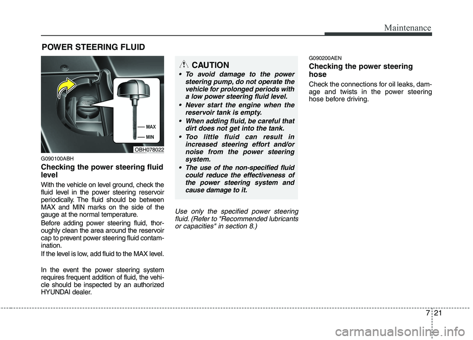
Checking the power steering fluid
level
With the vehicle on level ground, check the
fluid level in the power steering reservoir
periodically. The fluid should be between
MAX and MIN marks on the side of the
gauge at the normal temperature.
Before adding power steering fluid, thor-
oughly clean the area around the reservoir
cap to prevent power steering fluid contam-
ination.
If the level is low, add fluid to the MAX level.
In the event the power steering system
requires frequent addition of fluid, the vehi-
cle should be inspected by an authorized
HYUNDAI dealer.
Use only the specified power steeringfluid. (Refer to "Recommended lubricantsor capacities" in section 8.)
G090200AEN
Checking the power steering
hose
Check the connections for oil leaks, dam-
age and twists in the power steering
hose before driving.
CAUTION
• To avoid damage to the power steering pump, do not operate thevehicle for prolonged periods witha low power steering fluid level.
Never start the engine when the reservoir tank is empty.
When adding fluid, be careful that dirt does not get into the tank.
Too little fluid can result in increased steering effort and/ornoise from the power steeringsystem.
The use of the non-specified fluid could reduce the effectiveness ofthe power steering system andcause damage to it.
OBH078022
Page 367 of 432

733
Maintenance
G190300ABH
Reset items
Items should be reset after the battery
has been discharged or the battery has
been disconnected.
Auto up/down window (See section 4)
Sunroof (See section 4)
Driver position memory system
(See section 4)
Trip computer (See section 4)
Climate control system
(See section 4)
Clock (See section 4)
Audio (See section 4)
WARNING
Before performing maintenance
or recharging the battery, turn off
all accessories and stop the
engine.
The negative battery cable must
be removed first and installed
last when the battery is discon-
nected.
Operation related to the battery
should be done at an authorized
HYUNDAI dealer.
CAUTION
Keep the battery away from water
or any liquid.
The battery is in the trunk, so you
should be careful when you load
a container filled with liquid into
the trunk.
For your safety, use a genuine
HYUNDAI approved battery when
you replace the battery.
WARNING- Recharging
battery
When recharging the battery,
observe the following precautions:
The battery must be removed
from the vehicle and placed in an
area with good ventilation.
Do not allow cigarettes, sparks,
or flame near the battery.
Watch the battery during charg-
ing, and stop or reduce the charg-
ing rate if the battery cells begin
gassing (boiling) violently or if
the temperature of the electrolyte
of any cell exceeds 120°F (49°C).
Wear eye protection when check-
ing the battery during charging.
Disconnect the battery charger in
the following order.
1. Turn off the battery charger main
switch.
2. Unhook the negative clamp from
the negative battery terminal.
3. Unhook the positive clamp from
the positive battery terminal.
Page 379 of 432

745
Maintenance
Cold Tire Pressure: The amount of
air pressure in a tire, measured in
pounds per square inch (psi) or kilo-
pascals (kPa) before a tire has built
up heat from driving.
Curb Weight: This means the weight
of a motor vehicle with standard and
optional equipment including the
maximum capacity of fuel, oil and
coolant, but without passengers and
cargo.
DOT Markings: A code molded into
the sidewall of a tire signifying that
the tire is in compliance with the U.S.
Department of Transportation motor
vehicle safety standards. The DOT
code includes the Tire Identification
Number (TIN), an alphanumeric des-
ignator which can also identify the
tire manufacturer, production plant,
brand and date of production.
GVWR: Gross Vehicle Weight Rating
GAWR FRT: Gross Axle Weight
Rating for the Front Axle.
GAWR RR: Gross Axle Weight
Rating for the Rear axle.Intended Outboard Sidewall: The
side of an asymmetrical tire, that
must always face outward when
mounted on a vehicle.
Kilopascal (kPa): The metric unit for
air pressure.
Load Index: An assigned number
ranging from 1 to 279 that corre-
sponds to the load carrying capacity
of a tire.
Maximum Inflation Pressure: The
maximum air pressure to which a
cold tire may be inflated. The maxi-
mum air pressure is molded onto the
sidewall.
Maximum Load Rating: The load
rating for a tire at the maximum per-
missible inflation pressure for that
tire.
Maximum Loaded Vehicle Weight:
The sum of curb weight; accessory
weight; vehicle capacity weight; and
production options weight.
Normal Occupant Weight:The
number of occupants a vehicle is
designed to seat multiplied by 150
pounds (68 kg).Occupant Distribution: Designated
seating positions.
Outward Facing Sidewall:The side
of a asymmetrical tire that has a par-
ticular side that faces outward when
mounted on a vehicle. The outward
facing sidewall bears white lettering
or bears manufacturer, brand, and/or
model name molding that is higher or
deeper than the same moldings on
the inner facing sidewall.
Passenger (P-Metric) Tire: A tire
used on passenger cars and some
light duty trucks and multipurpose
vehicles.
Recommended Inflation Pressure:
Vehicle manufacturer's recommend-
ed tire inflation pressure and shown
on the tire placard.
Radial Ply Tire: A pneumatic tire in
which the ply cords that extend to the
beads are laid at 90 degrees to the
centerline of the tread.
Rim: A metal support for a tire and
upon which the tire beads are seated.
Sidewall: The portion of a tire
between the tread and the bead.
Page 382 of 432

Maintenance
48 7
FUSES
G210000ABH-EU
A vehicle’s electrical system is protected
from electrical overload damage by
fuses.This vehicle has 4 fuse panels, two locat-
ed in the driver’s side and passenger’s
side panel bolster, the others are in the
engine compartment.
If any of your vehicle’s lights, acces-
sories, or controls do not work, check the
appropriate circuit fuse. If a fuse has
blown, the element inside the fuse will be
melted.
If the electrical system does not work,
first check the driver’s side fuse panel.
Before replacing a blown fuse, discon-
nect the negative battery cable.
Always replace a blown fuse with one of
the same rating.
If the replacement fuse blows, this indi-
cates an electrical problem. Avoid using
the system involved and immediately
consult an authorized HYUNDAI dealer.
Three kinds of fuses are used: blade type
for lower amperage rating, cartridge type,
and fusible link for higher amperage rat-
ings.
✽ ✽
NOTICE
The actual fuse/relay panel label may
differ from equipped items.OBH072060 Normal Normal Blade type
Cartridge type
Fusible linkBlown
Blown
NormalBlown
WARNING - Fuse replace-
ment
Never replace a fuse with any-
thing but another fuse of the
same rating.
A higher capacity fuse could
cause damage and possibly a
fire.
Never install a wire or aluminum
foil instead of the proper fuse -
even as a temporary repair. It may
cause extensive wiring damage
and a possible fire.
CAUTION
Do not use a screwdriver or any
other metal object to remove fuses
because it may cause a short circuit
and damage the system.
Page 394 of 432
Maintenance
60 7
Description Fuse rating Protected component
ECU 30A Engine Control Relay
BLOWER 40A Blower Relay
IGN SW 2
(PRESAFETY PASS)40A Ignition Switch (IG 2, START), Presafety Seat Belt Passenger
RR HTD 40A E/R Junction Box Fuse (AQS 10A, WASHER 15A)
IGN SW 1
(PRESAFETY DRV)40A Ignition Switch (IG 1, ACC), Presafety Seat Belt Driver
A/CON 10A A/C Control Module
EPB 1 15A Electric Parking Brake Module
EPB 2 15A Electric Parking Brake Module
HORN 15A Horn Relay
IPM 10A IPM, Head Lamp (Low) Relay
AQS 10A AQS Sensor, Electronic Control Wiper Module, Blower Relay
DEICER 15A Heated Glass (FR) Relay
WASHER 15A Washer Relay
WIPER 30A Wiper Motor
HTD MIRR 10A A/C Control Module, Power Outside Mirror & Mirror Folding Motor LH/RH
TCU 15A TCM
AFLS 10A Head Lamp LH/RH
EHPS 10A EHPS Module
VDC/ESC 10A ESC Control Module, Multipurpose Check Connector
ECU(IG1) 10A ECM
IGN COIL 20A Ignition Coil #1,2,3,4,5,6
INJECTOR(B+) 15A Injector Drive Box
Page 395 of 432
761
Maintenance
Description Fuse rating Protected component
SENSOR 110AECM, Mass Air Flow Sensor, Oxygen Sensor #1,2,3,4
SENSOR 2 10ACanister Purge Control Solenoid Valve, Variable Intake Manifold Valve, Oil Control Valve, ECM,
Cooling Fan Relay, Immobilizer Module
SENSOR 3 10A ECM, Injector #1~#6, Fuel Pump Relay
H/LP RH 15A Head Lamp RH
H/LP LH 15A Head Lamp LH
INJECTOR(IG1) 10A Injector Drive Box
CRUSIE 10A Smart Cruise Control Module
STOP LP 10A Stop Lamp Switch, Stop Lamp Relay, Generator,Vacuum Switch
ECU(B+) 15A ECM,TCM,Injector Drive Box
ROOM LP 10A Room Lamp Relay
F/PUMP 20A Fuel Pump Relay, Fuel Pump Resistor
START 30A Start Solenoid