2014 FORD SUPER DUTY fuel
[x] Cancel search: fuelPage 41 of 82
FUEL SHUTOFF
In the event of a moderate to severe
collision, this vehicle is equipped with a
fuel pump shut-off feature that stops the
flow of fuel to the engine. Not every impact
will cause a shut-off.
After an accident, if the engine cranks but
does not start, this switch may have been
activated.
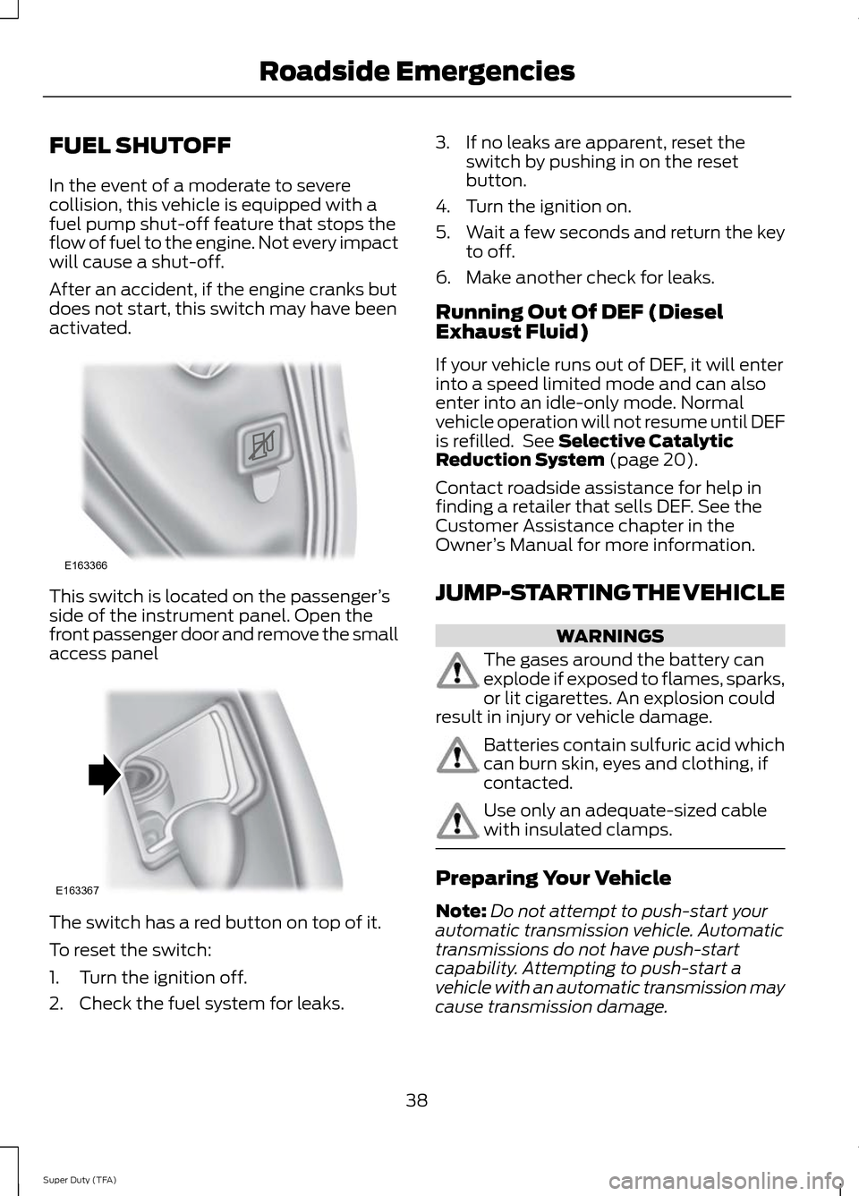
This switch is located on the passenger
’s
side of the instrument panel. Open the
front passenger door and remove the small
access panel The switch has a red button on top of it.
To reset the switch:
1. Turn the ignition off.
2. Check the fuel system for leaks. 3. If no leaks are apparent, reset the
switch by pushing in on the reset
button.
4. Turn the ignition on.
5. Wait a few seconds and return the key
to off.
6. Make another check for leaks.
Running Out Of DEF (Diesel
Exhaust Fluid)
If your vehicle runs out of DEF, it will enter
into a speed limited mode and can also
enter into an idle-only mode. Normal
vehicle operation will not resume until DEF
is refilled. See Selective Catalytic
Reduction System (page 20).
Contact roadside assistance for help in
finding a retailer that sells DEF. See the
Customer Assistance chapter in the
Owner ’s Manual for more information.
JUMP-STARTING THE VEHICLE WARNINGS
The gases around the battery can
explode if exposed to flames, sparks,
or lit cigarettes. An explosion could
result in injury or vehicle damage. Batteries contain sulfuric acid which
can burn skin, eyes and clothing, if
contacted.
Use only an adequate-sized cable
with insulated clamps.
Preparing Your Vehicle
Note:
Do not attempt to push-start your
automatic transmission vehicle. Automatic
transmissions do not have push-start
capability. Attempting to push-start a
vehicle with an automatic transmission may
cause transmission damage.
38
Super Duty (TFA) Roadside EmergenciesE163366 E163367
Page 42 of 82
Note:
Use only a 12-volt supply to start your
vehicle.
Note: Do not disconnect the battery of the
disabled vehicle as this could damage the
vehicle's electrical system.
Park the booster vehicle close to the hood
of the disabled vehicle, making sure the
two vehicles do not touch. Turn all
accessories off.
Connecting the Jumper Cables WARNING
Do not attach the cables to fuel lines,
engine rocker covers, the intake
manifold or electrical components
as grounding points. Stay clear of moving
parts. To avoid reverse polarity
connections, make sure that you correctly
identify the positive (+) and negative (-)
terminals on both the disabled and booster
vehicles before connecting the cables. Note:
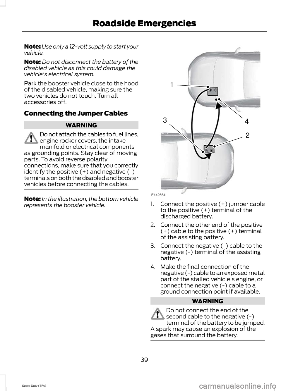
In the illustration, the bottom vehicle
represents the booster vehicle. 1.
Connect the positive (+) jumper cable
to the positive (+) terminal of the
discharged battery.
2. Connect the other end of the positive (+) cable to the positive (+) terminal
of the assisting battery.
3. Connect the negative (-) cable to the negative (-) terminal of the assisting
battery.
4. Make the final connection of the negative (-) cable to an exposed metal
part of the stalled vehicle's engine, or
connect the negative (-) cable to a
ground connection point if available. WARNING
Do not connect the end of the
second cable to the negative (-)
terminal of the battery to be jumped.
A spark may cause an explosion of the
gases that surround the battery. 39
Super Duty (TFA) Roadside Emergencies4
2
1
3
E142664
Page 44 of 82
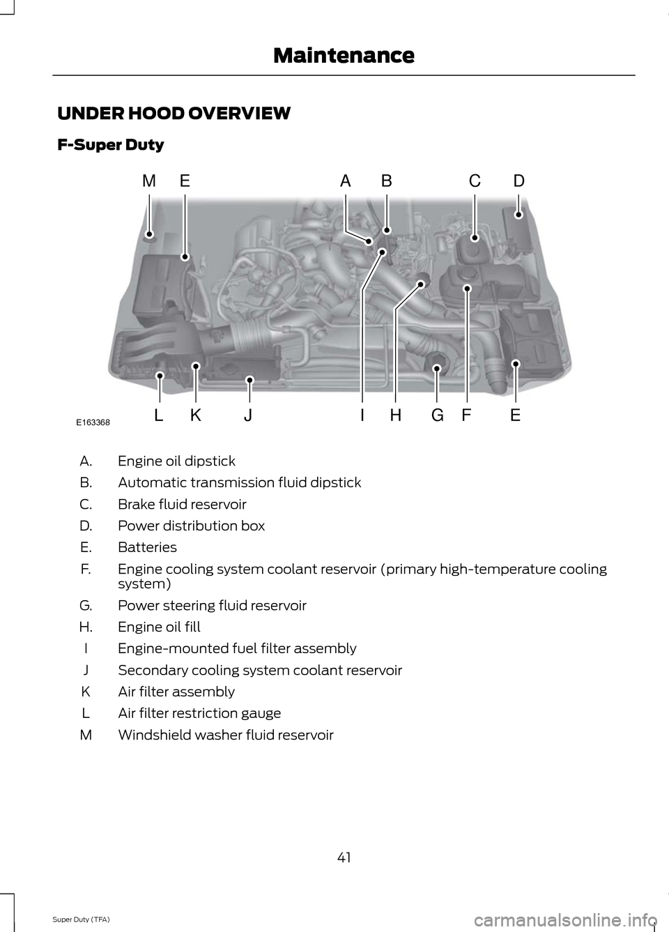
UNDER HOOD OVERVIEW
F-Super Duty
Engine oil dipstick
A.
Automatic transmission fluid dipstick
B.
Brake fluid reservoir
C.
Power distribution box
D.
Batteries
E.
Engine cooling system coolant reservoir (primary high-temperature cooling
system)
F.
Power steering fluid reservoir
G.
Engine oil fill
H.
Engine-mounted fuel filter assembly
I
Secondary cooling system coolant reservoir
J
Air filter assembly
K
Air filter restriction gauge
L
Windshield washer fluid reservoir
M
41
Super Duty (TFA) MaintenanceE163368
MEBC
EGJKLF
DA
HI
Page 45 of 82
Scheduled Maintenance
The scheduled maintenance services in
the scheduled maintenance information
of this supplement are required because
they are considered essential to the life
and performance of your vehicle. See
General Maintenance Information
(page 58).
Use only recommended fuel, lubricants,
fluids and service parts conforming to Ford
specifications. Motorcraft® parts are
designed and built for best performance
in your vehicle.
ENGINE OIL CHECK
Because it is normal to add some oil
between oil changes, check your engine oil
level each time you stop for fuel. To check
the engine oil level consistently and
accurately, the following procedure is
recommended:
1. Have engine at normal operating temperature (at least into the NORMAL
range on the engine coolant
temperature gauge).
2. Park the vehicle on a level surface, then
turn off the engine and open the hood.
3. Allow at least 20 minutes after engine
shutdown to ensure that the oil
contained in the upper parts of the
engine has returned to the oil pan.
4. Protecting yourself from engine heat, pull out the dipstick, wipe it clean and
reinsert fully.
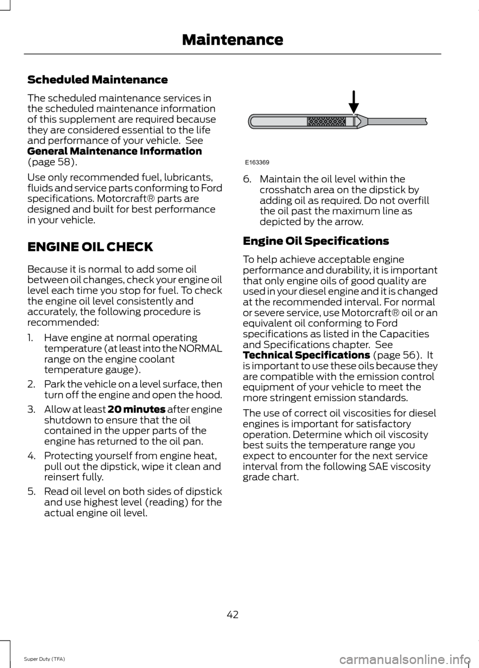
5. Read oil level on both sides of dipstick
and use highest level (reading) for the
actual engine oil level. 6. Maintain the oil level within the
crosshatch area on the dipstick by
adding oil as required. Do not overfill
the oil past the maximum line as
depicted by the arrow.
Engine Oil Specifications
To help achieve acceptable engine
performance and durability, it is important
that only engine oils of good quality are
used in your diesel engine and it is changed
at the recommended interval. For normal
or severe service, use Motorcraft® oil or an
equivalent oil conforming to Ford
specifications as listed in the Capacities
and Specifications chapter. See
Technical Specifications
(page 56). It
is important to use these oils because they
are compatible with the emission control
equipment of your vehicle to meet the
more stringent emission standards.
The use of correct oil viscosities for diesel
engines is important for satisfactory
operation. Determine which oil viscosity
best suits the temperature range you
expect to encounter for the next service
interval from the following SAE viscosity
grade chart.
42
Super Duty (TFA) MaintenanceE163369
Page 47 of 82
5.
Reset the Intelligent Oil Life Monitor™.
See the Information Displays chapter
in the Owner's Manual for more
information.
Engine lubrication for severe service
operation
The following conditions define severe
operation for which engine operation with
SAE 5W-40 API CJ-4 is recommended. Oil
and oil filter change intervals will be
determined by the Intelligent Oil Life
Monitor™ as noted previously.
• Frequent or extended idling (over 10
minutes per hour of normal driving)
• Low-speed operation/stationary use
• If vehicle is operated in sustained
ambient temperatures below -10°F
(-23°C) or above 100°F (38°C)
• Frequent low-speed operation,
consistent heavy traffic less than 25
mph (40 km/h)
• Operating in severe dust conditions
• Operating the vehicle off road
• Towing a trailer over 1,000 miles (1,600
km)
• Sustained, high-speed driving at Gross
Vehicle Weight Rating (maximum
loaded weight for vehicle operation)
• Use of fuels with sulfur content other
than ultra-low sulfur diesel (ULSD)
• Use of high-sulfur diesel fuel
ENGINE COOLANT CHECK
Checking the Engine Coolant
The concentration and level of the engine
coolant should be checked at the intervals
listed in the scheduled maintenance
information. See Scheduled
Maintenance (page 58). Note:
Make sure that the level is between
the MIN and MAX marks on the coolant
reservoirs.
Note: Coolant expands when it is hot. The
level may extend beyond the MAX mark
Note: If the level is at the MIN mark, below
the MIN mark, or empty, add coolant
immediately. See
Adding Engine Coolant
in this chapter.
Note: The coolant concentration should be
maintained within 48% to 50%, which
equates to a freeze point between -30 °F
(-34 °C) and -34 °F (-37 °C).
Note: For best results, the coolant
concentration should be tested with a
refractometer such as Rotunda tool
300-ROB75240 available from your dealer.
Ford does not recommend the use of
hydrometers or coolant test strips for
measuring coolant concentrations.
Note: Automotive fluids are not
interchangeable. Do not use engine coolant
or antifreeze or windshield washer fluid
outside of its specified function and vehicle
location.
Adding Engine Coolant WARNINGS
Do not add engine coolant when the
engine is hot. Steam and scalding
liquids released from a hot cooling
system can burn you badly. Also, you can
be burned if you spill coolant on hot engine
parts. Do not put engine coolant in the
windshield washer fluid container. If
sprayed on the windshield, engine
coolant could make it difficult to see
through the windshield.
44
Super Duty (TFA) Maintenance
Page 52 of 82
Coolant Change
At specific mileage intervals, as listed in
the scheduled maintenance information,
the coolant should be changed. The
optional information display, if equipped,
will also display the message COOLANT
CHANGE REQUIRED at this time.
See Capacities and Specifications
(page 54). for the proper coolant.
Engine-driven Cooling Fan (Fan
Clutch)
Your vehicle is equipped with an engine
driven cooling fan drive (also called a fan
clutch). This fan drive changes the fan
speed to match the vehicle ’s changing
cooling air flow requirements. Fan speed,
fan noise level and fuel consumption all
will increase based on the driving
conditions that include trailer towing, hill
climbing, heavy loads, high speed and high
ambient temperature, individually or in
combination.
The fan drive is designed to provide the
minimum fan speed (and resulting
minimum fan noise and fuel consumption)
required to meet the ever changing vehicle
cooling air flow requirements. You will hear
the amount of fan noise increasing and
decreasing as the engine power
requirements and vehicle driving conditions
change as you drive. This is to be expected
as being normal to the operation of your
vehicle. High levels of fan noise might also
be heard when your engine is first started,
and should normally decrease after driving
for a short time. CHANGING THE ENGINE AIR
FILTER
Air Filter Restriction Gauge WARNING
To reduce the risk of vehicle damage
and/or personal burn injuries do not
start your engine with the air filter
removed and do not remove it while the
engine is running. Note:
Vehicle operation in heavy snowfall
or extreme rain conditions may feed
excessive amounts of snow/water into the
air intake system. This could plug/soak the
air filter with snow and may cause the
engine to lose power and possibly shut
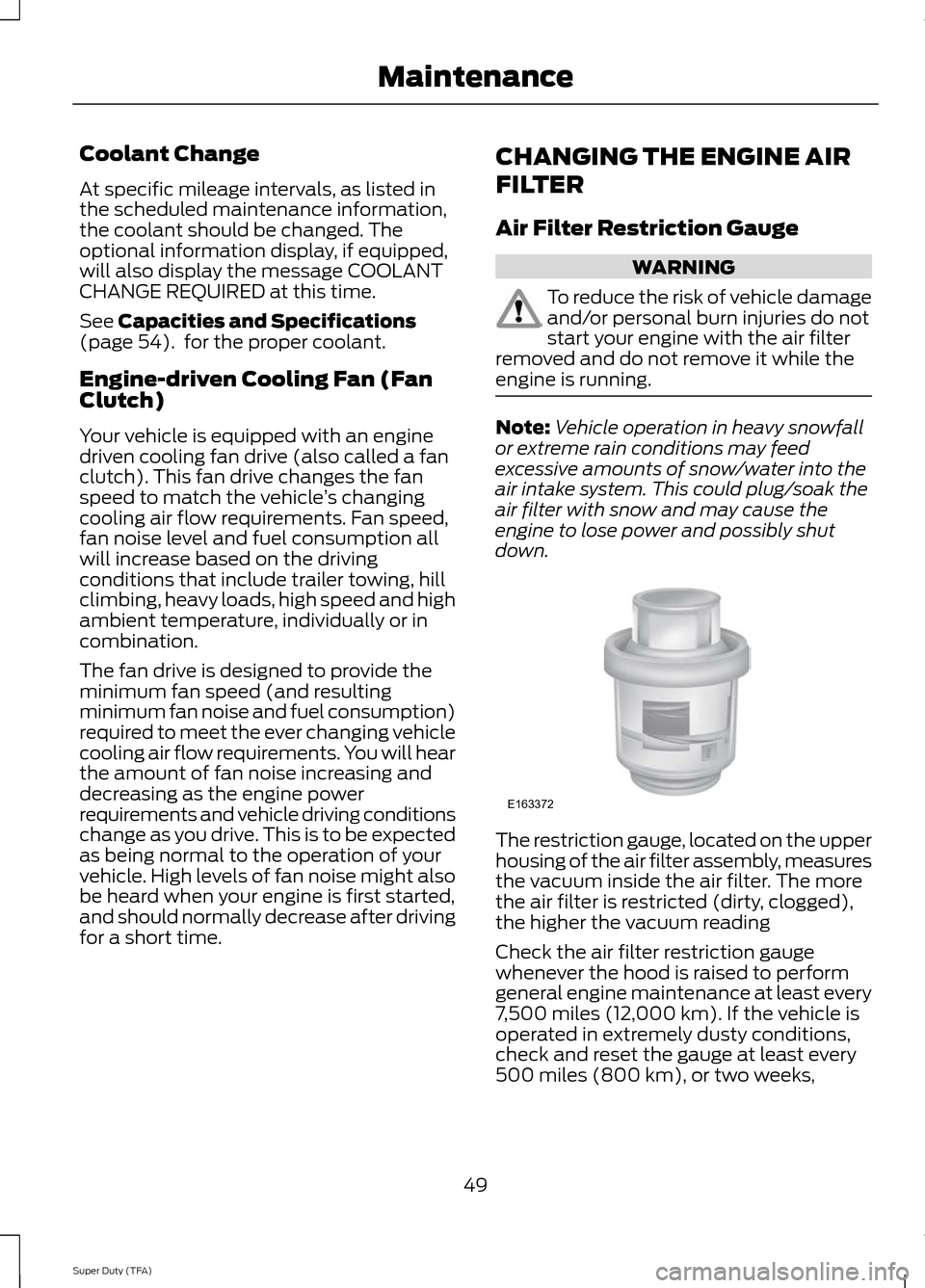
down. The restriction gauge, located on the upper
housing of the air filter assembly, measures
the vacuum inside the air filter. The more
the air filter is restricted (dirty, clogged),
the higher the vacuum reading
Check the air filter restriction gauge
whenever the hood is raised to perform
general engine maintenance at least every
7,500 miles (12,000 km). If the vehicle is
operated in extremely dusty conditions,
check and reset the gauge at least every
500 miles (800 km), or two weeks,
49
Super Duty (TFA) MaintenanceE163372
Page 53 of 82
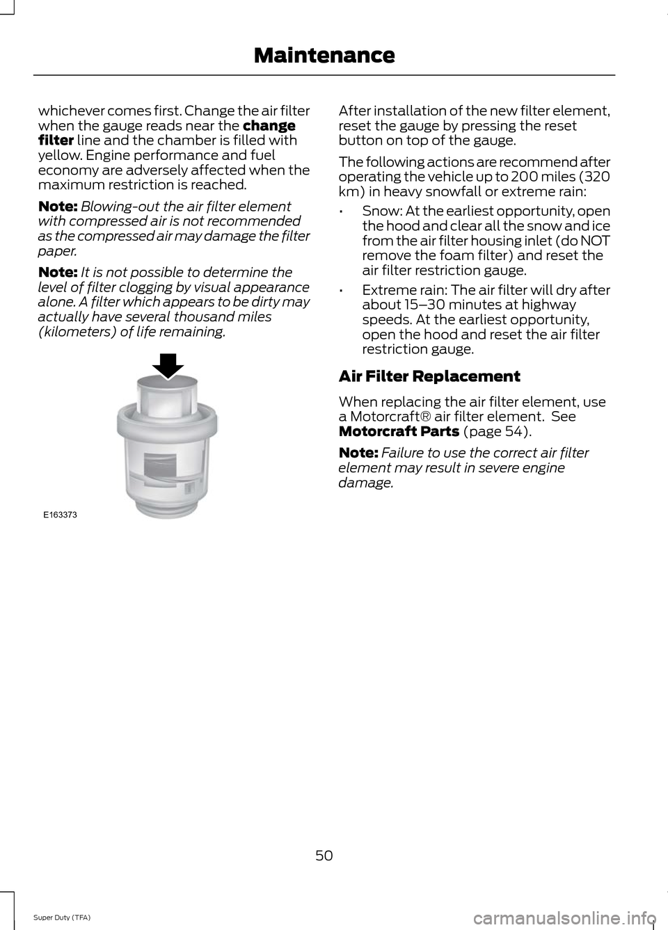
whichever comes first. Change the air filter
when the gauge reads near the change
filter line and the chamber is filled with
yellow. Engine performance and fuel
economy are adversely affected when the
maximum restriction is reached.
Note: Blowing-out the air filter element
with compressed air is not recommended
as the compressed air may damage the filter
paper.
Note: It is not possible to determine the
level of filter clogging by visual appearance
alone. A filter which appears to be dirty may
actually have several thousand miles
(kilometers) of life remaining. After installation of the new filter element,
reset the gauge by pressing the reset
button on top of the gauge.
The following actions are recommend after
operating the vehicle up to 200 miles (320
km) in heavy snowfall or extreme rain:
•
Snow: At the earliest opportunity, open
the hood and clear all the snow and ice
from the air filter housing inlet (do NOT
remove the foam filter) and reset the
air filter restriction gauge.
• Extreme rain: The air filter will dry after
about 15– 30 minutes at highway
speeds. At the earliest opportunity,
open the hood and reset the air filter
restriction gauge.
Air Filter Replacement
When replacing the air filter element, use
a Motorcraft® air filter element. See
Motorcraft Parts
(page 54).
Note: Failure to use the correct air filter
element may result in severe engine
damage.
50
Super Duty (TFA) MaintenanceE163373
Page 58 of 82
Ford Part Number
Component
FD-4615
Fuel filter kit (2
included -
engine and
frame rail
mounted )
BXT-65-750
Battery (2
Required)
1 Failure to use the correct air filter element may result in severe engine damage. The
customer warranty may be void for any damage to the engine if the correct air filter
element is not used.
55
Super Duty (TFA) Capacities and Specifications