2014 FORD F250 ignition
[x] Cancel search: ignitionPage 186 of 460
be: 635 kilograms - (2 x 99
kilograms) - (12 x 45 kilograms) =
635 - 198 - 540 = -103 kilograms.
You will need to reduce the load
weight by at least 240 pounds
(104 kilograms). If you remove
three 100-pound (45-kilogram)
cement bags, then the load
calculation would be:1400 - (2 x
220) - (9 x 100) = 1400 - 440 -
900 = 60 pounds. Now you have
the load capacity to transport the
cement and your friend home. In
metric units, the calculation would
be: 635 kilograms - (2 x 99
kilograms) - (9 x 45 kilograms) =
635 - 198 - 405 = 32 kilograms.
The above calculations also
assume that the loads are
positioned in your vehicle in a
manner that does not overload
the Front or the Rear Gross Axle
Weight Rating specified for your
vehicle on the Safety Compliance
Certification Label. The label shall
be affixed to either the door hinge
pillar, door-latch post, or the door
edge that meets the door-latch
post, next to the driver's seating
position.
Special Loading Instructions
for Owners of Pick-up Trucks
and Utility-type Vehicles WARNING
Loaded vehicles may handle
differently than unloaded
vehicles. Extra precautions, such
as slower speeds and increased
stopping distance, should be
taken when driving a heavily
loaded vehicle. Your vehicle can haul more cargo
and people than most passenger
cars. Depending upon the type
and placement of the load,
hauling cargo and people may
raise the center of gravity of the
vehicle.
TAILGATE
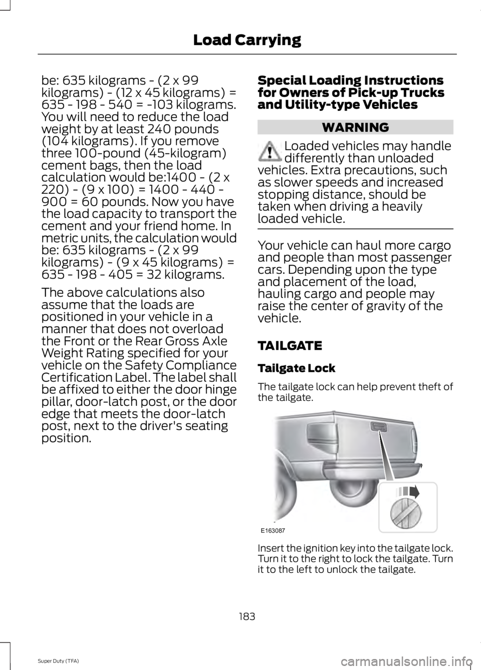
Tailgate Lock
The tailgate lock can help prevent theft of
the tailgate.
Insert the ignition key into the tailgate lock.
Turn it to the right to lock the tailgate. Turn
it to the left to unlock the tailgate.
183
Super Duty (TFA) Load CarryingE163087
Page 195 of 460
The rating for the tow vehicle's braking
system operation is at the gross vehicle
weight rating, not the gross combined
weight rating.
Separate functioning brake systems
are required for safe control of towed
vehicles and trailers weighing more
than 1500 pounds (680 kilograms)
when loaded.
Integrated Trailer Brake Controller (If
Equipped)
WARNING
The Ford trailer brake controller has
been verified to be compatible with
trailers having electric-actuated
drum brakes (one to four axles) and some
electric-over-hydraulic brakes. It will not
activate hydraulic surge-style trailer
brakes. It is the responsibility of the
customer to ensure that the trailer brakes
are adjusted appropriately, functioning
normally and all electric connections are
properly made. Failure to do so may result
in loss of vehicle control, crash or serious
injury. When used properly, the trailer brake
controller assists in smooth and effective
trailer braking by powering the trailer
’s
electric or electric-over-hydraulic brakes
with a proportional output based on the
towing vehicle ’s brake pressure. Ford has tested the trailer brake controller
to be compatible with several major
brands of electric-over-hydraulic trailer
brakes. Contact an authorized dealer for
information on which brands you can use.
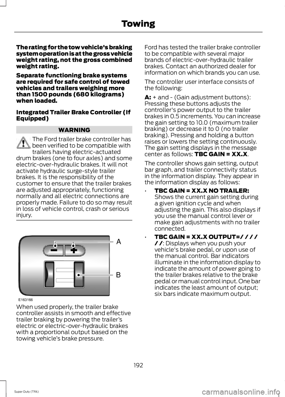
The controller user interface consists of
the following:
A: + and - (Gain adjustment buttons):
Pressing these buttons adjusts the
controller's power output to the trailer
brakes in 0.5 increments. You can increase
the gain setting to 10.0 (maximum trailer
braking) or decrease it to 0 (no trailer
braking). Pressing and holding a button
raises or lowers the setting continuously.
The gain setting displays in the message
center as follows:
TBC GAIN = XX.X.
The controller shows gain setting, output
bar graph, and trailer connectivity status
in the information display. They appear in
the information display as follows:
• TBC GAIN = XX.X NO TRAILER:
Shows the current gain setting during
a given ignition cycle and when
adjusting the gain. This also displays if
you use the manual control lever or
make gain adjustments with no trailer
connected.
• TBC GAIN = XX.X OUTPUT=/ / / /
/ /
: Displays when you push your
vehicle's brake pedal, or upon use of
the manual control. Bar indicators
illuminate in the information display to
indicate the amount of power going to
the trailer brakes relative to the brake
pedal or manual control input. One bar
indicates the least amount of output;
six bars indicate maximum output.
192
Super Duty (TFA) TowingB
A
E163166
Page 196 of 460
•
TRAILER CONNECTED: Displays
when the system senses a correct
trailer wiring connection (a trailer with
electric trailer brakes) during a given
ignition cycle.
• TRAILER DISCONNECTED:
Displays,
accompanied by a single audible time,
when the system senses a trailer
connection and then a disconnection,
either intentional or unintentional,
during a given ignition cycle. It also
displays if a truck or trailer-wiring fault
occurs causing the trailer to appear
disconnected. This message can also
display if you use the manual control
lever without a trailer connected.
B:
Manual control lever: Slide the control
lever to the left to turn on the trailer's
electric brakes independent of the tow
vehicle's See the following Procedure for
adjusting gain section for instructions on
proper use of this feature. If you use the
manual control while the brake is also
applied, the greater of the two inputs
determines the power sent to the trailer
brakes.
• Stop lamps: Using the manual control
lever illuminates both the trailer brake
lamps and your vehicle brake lamps
except the center high-mount stop
lamp, if you make the proper electrical
connection to the trailer. Pressing your
vehicle brake pedal also illuminates
both trailer and vehicle brake lamps.
Procedure for Adjusting Gain
Note: Only perform this procedure in a
traffic-free environment at speeds of
approximately 20-25 mph (30-40 km/h).
The gain setting sets the trailer brake
controller for the specific towing condition.
You should change the setting as towing
conditions change. Changes to towing
conditions include trailer load, vehicle load,
road conditions and weather. The gain should be set to provide the
maximum trailer braking assistance while
making sure the trailer wheels do not lock
when using the brakes. Locked trailer
wheels may lead to trailer instability.
1.
Make sure the trailer brakes are in good
working condition, functioning normally
and properly adjusted. See your trailer
dealer if necessary.
2. Hook up the trailer and make the electrical connections according to the
trailer manufacturer's instructions.
3. When you plug in a trailer with electric or electric-over-hydraulic brakes,
TRAILER CONNECTED
appears in
the information display.
4. Use the gain adjustment (+ and -) buttons to increase or decrease the
gain setting to the desired starting
point. A gain setting of 6.0 is a good
starting point for heavier loads.
5. In a traffic-free environment, tow the trailer on a dry, level surface at a speed
of 20-25 mph (30-40 km/h) and
squeeze the manual control lever
completely.
6. If the trailer wheels lock up, indicated by squealing tires, reduce the gain
setting. If the trailer wheels turn freely,
increase the gain setting. Repeat Steps
5 and 6 until the gain setting is at a
point just below trailer wheel lock-up.
If towing a heavier trailer, trailer wheel
lock-up may not be attainable even
with the maximum gain setting of 10.
Explanation of Information Display
Warning Messages
Note: An authorized dealer can diagnose
the trailer brake controller to determine
exactly which trailer fault has occurred.
However, your Ford warranty does not cover
this diagnosis if the fault is with the trailer.
193
Super Duty (TFA) Towing
Page 197 of 460
TRAILER BRAKE MODULE FAULT:
Displays in response to faults sensed by
the trailer brake controller, accompanied
by a single tone. If this message appears,
contact an authorized dealer as soon as
possible for diagnosis and repair. The
controller may still function, but
performance may be degraded.
WIRING FAULT ON TRAILER: Displays
when there is a short circuit on the electric
brake output wire. If the
WIRING FAULT
ON TRAILER message displays,
accompanied by a single tone, with no
trailer connected, the problem is with your
vehicle wiring between the trailer brake
controller and the 7-pin connector at the
bumper. If the message only displays with
a trailer connected, the problem is with the
trailer wiring. Consult your trailer dealer for
assistance. This can be a short to ground
(such as a chaffed wire), short to voltage
(such as a pulled pin on trailer emergency
breakaway battery) or the trailer brakes
may be drawing too much current.
Points to Remember
Note: Do not attempt removal of the trailer
brake controller without consulting the
Workshop Manual. Damage to the unit may
result.
• Adjust gain setting before using the
trailer brake controller for the first time.
• Adjust gain setting, using the procedure
above, whenever road, weather and
trailer or vehicle loading conditions
change from when the gain was initially
set.
• Only use the manual control lever for
proper adjustment of the gain during
trailer setup. Misuse, such as
application during trailer sway, could
cause instability of trailer or tow
vehicle. •
Avoid towing in adverse weather
conditions. The trailer brake controller
does not provide anti-lock control of
the trailer wheels. Trailer wheels can
lock up on slippery surfaces, resulting
in reduced stability of trailer and tow
vehicle.
• The trailer brake controller is equipped
with a feature that reduces output at
vehicle speeds below 11 mph (18 km/h)
so trailer and vehicle braking is not jerky
or harsh. This feature is only available
when applying the brakes using your
vehicle's brake pedal, not the
controller.
• The controller interacts with the brake
control system and powertrain control
system of your vehicle to provide the
best performance on different road
conditions.
• Your vehicle's brake system and the
trailer brake system work
independently of each other. Changing
the gain setting on the controller does
not affect the operation of your
vehicle's brakes whether you attach a
trailer or not.
• When you switch the engine off, the
controller output is disabled and the
display and module shut down. The
controller module and display turn on
when you switch the ignition on.
• The trailer brake controller is only a
factory-installed or dealer-installed
item. Ford is not responsible for
warranty or performance of the
controller due to misuse or customer
installation.
194
Super Duty (TFA) Towing
Page 208 of 460

HAZARD WARNING FLASHERS
Note:
The hazard warning flashers will
operate when the ignition is in any position
or if the key is not in the ignition. If used
when the engine is not running, the battery
will lose charge. As a result, there may be
insufficient power to restart your engine. In some models, the hazard
flasher control is located on the
instrument panel.
In other models, this feature is located on
the steering column, just behind the
steering wheel. Use your hazard warning flashers when
your vehicle is creating a safety hazard for
other motorists.
•
Press the flasher control and all front
and rear direction indicators flash.
• Press the flasher control again to turn
them off.
FUEL SHUTOFF WARNING
Failure to inspect and, if necessary,
repair fuel leaks after a collision may
increase the risk of fire and serious
injury. Ford Motor Company recommends
that the fuel system be inspected by an
authorized dealer after any collision. In the event of a moderate to severe
collision, this vehicle is equipped with a
fuel pump shut-off feature that stops the
flow of fuel to the engine. Not every impact
will cause a shut-off.
Should your vehicle shut off after a
collision, you may restart your vehicle by
doing the following:
1. Turn the ignition off.
2. Turn the ignition to crank.
3. Turn the ignition off.
4.
Turn the ignition on again to re-enable
the fuel pump.
JUMP-STARTING THE VEHICLE WARNINGS
The gases around the battery can
explode if exposed to flames, sparks,
or lit cigarettes. An explosion could
result in injury or vehicle damage. Batteries contain sulfuric acid which
can burn skin, eyes and clothing, if
contacted.
Use only an adequate-sized cable
with insulated clamps.
Preparing Your Vehicle
Note:
Do not attempt to push-start your
automatic transmission vehicle. Automatic
transmissions do not have push-start
capability. Attempting to push-start a
vehicle with an automatic transmission may
cause transmission damage.
Note: Use only a 12-volt supply to start your
vehicle.
Note: Do not disconnect the battery of the
disabled vehicle as this could damage the
vehicle's electrical system.
205
Super Duty (TFA) Roadside EmergenciesE142663 E161463
Page 224 of 460

Protected components
Fuse amp rating
Fuse or relay number
Auxiliary switch relay #3
10A
9
Run/accessory relay, Customer access
feed
10A
10
Instrument cluster
10A
11
Interior lighting, Lighted running board
lamps
15A
12
Right turn signals and brake lamps, Right
trailer tow stop turn relay
15A
13
Left turn signals and brake lamps, Left
trailer tow stop turn relay
15A
14
High-mounted stop lamps, Backup lamps,
Trailer tow backup relay, Reverse signal
interior mirror
15A
15
Right low beam headlamp
10A
16
Left low beam headlamp
10A
17
Keypad illumination, Passive anti-theft
transceiver, Powertrain control module,
Brake shift interlock
10A
18
Subwoofer, Amplifier
20A
19
Power door locks
20A
20
Brake on/off switch
10A
21
Horn
20A
22
Not used (spare)
15A
23
Steering wheel control module, Diagnostic
connector, Power fold mirror relay, Remote
keyless entry, Electronic finish panel
15A
24
Not used (spare)
15A
25
Steering wheel control module
5A
26
Not used (spare)
20A
27
Ignition switch
15A
28
SYNC, GPS module, Radio faceplate
20A
29
221
Super Duty (TFA) Fuses
Page 240 of 460

control fan, heated steering wheel, audio
and navigation system. A message may be
shown in the information displays to alert
the driver that battery protection actions
are active. These messages are only for
notification that an action is taking place,
and not intended to indicate an electrical
problem or that the battery requires
replacement.
Electrical accessory installation
To ensure proper operation of the BMS,
any electrical devices that are added to
the vehicle should not have their ground
connection made directly at the negative
battery post. A connection at the negative
battery post can cause inaccurate
measurements of the battery condition
and potential incorrect system operation.
Note:
Electrical or electronic accessories
added to the vehicle by the dealer or the
owner may adversely affect battery
performance and durability, and may also
affect the performance of other electrical
systems in the vehicle.
When a battery replacement is required,
the battery should only be replaced with
a Ford recommended replacement battery
which matches the electrical requirements
of the vehicle. After battery replacement,
or in some cases after charging the battery
with the external charger, the BMS requires
eight hours of vehicle sleep time (key off
with doors closed) to relearn the new
battery state of charge. Prior to relearning
the state of charge, the BMS may disable
electrical features (to protect the battery)
earlier than normal. CHECKING THE WIPER
BLADES Run the tip of your fingers over the edge of
the blade to check for roughness.
Clean the wiper blades with washer fluid
or water applied with a soft sponge or
cloth.
CHANGING THE WIPER
BLADES
You can manually move the wiper arms
when the ignition is off. This allows for ease
of blade replacement and cleaning under
the blades.
1. Pull the wiper blade and arm away
from the glass.
237
Super Duty (TFA) MaintenanceE142463 E165804
Page 241 of 460
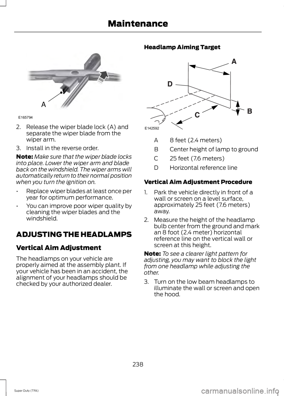
2. Release the wiper blade lock (A) and
separate the wiper blade from the
wiper arm.
3. Install in the reverse order.
Note: Make sure that the wiper blade locks
into place. Lower the wiper arm and blade
back on the windshield. The wiper arms will
automatically return to their normal position
when you turn the ignition on.
• Replace wiper blades at least once per
year for optimum performance.
• You can improve poor wiper quality by
cleaning the wiper blades and the
windshield.
ADJUSTING THE HEADLAMPS
Vertical Aim Adjustment
The headlamps on your vehicle are
properly aimed at the assembly plant. If
your vehicle has been in an accident, the
alignment of your headlamps should be
checked by your authorized dealer. Headlamp Aiming Target 8 feet (2.4 meters)
A
Center height of lamp to ground
B
25 feet (7.6 meters)
C
Horizontal reference line
D
Vertical Aim Adjustment Procedure
1. Park the vehicle directly in front of a wall or screen on a level surface,
approximately 25 feet (7.6 meters)
away.
2. Measure the height of the headlamp bulb center from the ground and mark
an 8 foot (2.4 meter) horizontal
reference line on the vertical wall or
screen at this height.
Note: To see a clearer light pattern for
adjusting, you may want to block the light
from one headlamp while adjusting the
other.
3. Turn on the low beam headlamps to illuminate the wall or screen and open
the hood.
238
Super Duty (TFA) MaintenanceA
E165794 E142592