2014 FORD F250 ECU
[x] Cancel search: ECUPage 187 of 460

Tailgate Removal
WARNING
Always properly secure cargo to
prevent shifting cargo or cargo falling
from vehicle, which could result in
compromised vehicle stability and serious
personal injury to vehicle occupants or
others. You can remove the tailgate for more
loading room.
Note:
Skip to Step 4 if your vehicle does
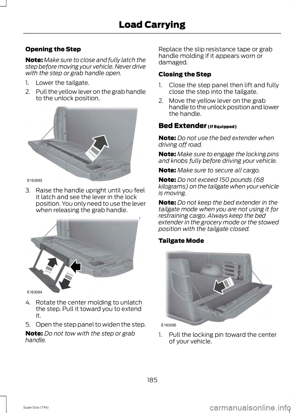
not have a rearview camera. 1. Locate and disconnect the rearview
camera in-line connector. It is under
the pickup box on the right-hand side
of the vehicle near the spare tire.
2. There is a tethered cap on the wire assembly. Install it on the in-line
connector that remains under the
pickup box.
3. Partially lower the tailgate. Carefully feed the tailgate harness up through
the gap between the pickup box and
the bumper and place it out of the way
under the pickup box.
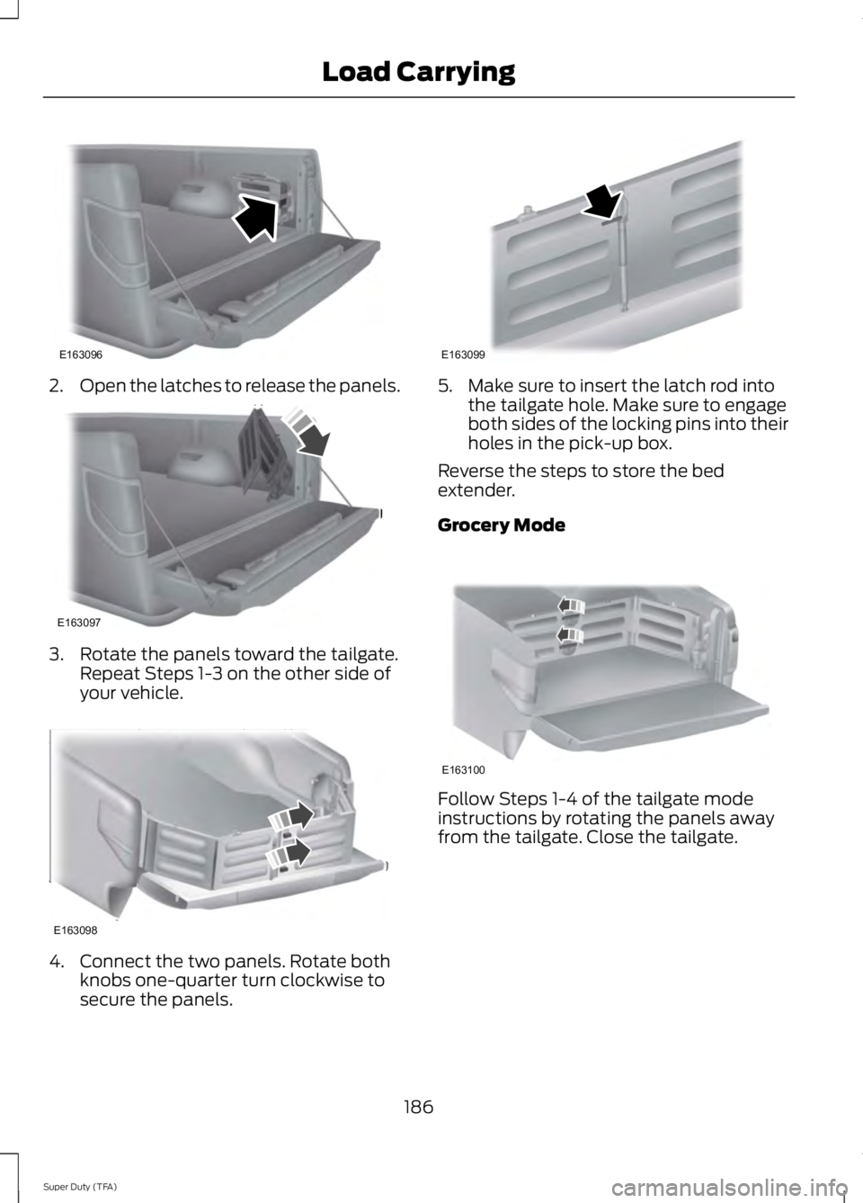
4. Lower the tailgate. 5. Use a screwdriver to gently pry the
spring clip on each connector past the
head of the support screw. Disconnect
the cable.
6. Disconnect the other cable.
7. Lift the tailgate to a 45-degree angle from horizontal.
8. Lift the right side off its hinge.
9. Lift the tailgate to an 80-degree angle
from horizontal.
10. Remove the tailgate from the left side
hinge by sliding it to the right.
Reverse the steps to reinstall the tailgate.
Tailgate Step (If Equipped)
Use the step to make entering the truck
bed easier.
To reduce the risk of falling:
• Only operate the step when your
vehicle is on a level surface.
• Only operate the step in areas with
sufficient lighting.
• Always open the step panel to widen
the step.
• Always use the grab handle when
climbing on the step.
• Do not use the step with bare feet.
• Make sure the step is clean before use.
• Keep the step load, you plus the load,
below 350 pounds (159 kilograms).
184
Super Duty (TFA) Load CarryingE163090 E163092
Page 188 of 460

Opening the Step
Note:
Make sure to close and fully latch the
step before moving your vehicle. Never drive
with the step or grab handle open.
1. Lower the tailgate.
2. Pull the yellow lever on the grab handle
to the unlock position. 3. Raise the handle upright until you feel
it latch and see the lever in the lock
position. You only need to use the lever
when releasing the grab handle. 4. Rotate the center molding to unlatch
the step. Pull it toward you to extend
it.
5. Open the step panel to widen the step.
Note: Do not tow with the step or grab
handle. Replace the slip resistance tape or grab
handle molding if it appears worn or
damaged.
Closing the Step
1. Close the step panel then lift and fully
close the step into the tailgate.
2. Move the yellow lever on the grab handle to the unlock position and lower
the handle.
Bed Extender (If Equipped)
Note: Do not use the bed extender when
driving off road.
Note: Make sure to engage the locking pins
and knobs fully before driving your vehicle.
Note: Make sure to secure all cargo.
Note: Do not exceed 150 pounds (68
kilograms) on the tailgate when your vehicle
is moving.
Note: Do not keep the bed extender in the
tailgate mode when you are not using it for
restraining cargo. Always keep the bed
extender in the grocery mode or the stowed
position with the tailgate closed.
Tailgate Mode 1. Pull the locking pin toward the center
of your vehicle.
185
Super Duty (TFA) Load CarryingE163093 E163094 E163095
Page 189 of 460

2.
Open the latches to release the panels. 3. Rotate the panels toward the tailgate.
Repeat Steps 1-3 on the other side of
your vehicle. 4. Connect the two panels. Rotate both
knobs one-quarter turn clockwise to
secure the panels. 5. Make sure to insert the latch rod into
the tailgate hole. Make sure to engage
both sides of the locking pins into their
holes in the pick-up box.
Reverse the steps to store the bed
extender.
Grocery Mode Follow Steps 1-4 of the tailgate mode
instructions by rotating the panels away
from the tailgate. Close the tailgate.
186
Super Duty (TFA) Load CarryingE163096 E163097 E163098 E163099 E163100
Page 194 of 460

Once the trailer is level or slightly nose
down toward the vehicle:
•
Lock the bar tension adjuster in place.
• Check that the trailer tongue securely
attaches and locks onto the hitch.
• Install safety chains, lighting, and trailer
brake controls as required by law or the
trailer manufacturer.
Fifth-wheel Trailer Hitch (If Equipped) WARNINGS
The mounting pads in the bed are
specifically designed for certain
fifth-wheel trailer hitches and
gooseneck ball hitches. Do not use these
mounting pads for other purposes. Doing
so could result in vehicle structural
damage, loss of vehicle control, and
personal injury. Contact an authorized
dealer to purchase gooseneck and
fifth-wheel hitches that are compatible
with your vehicle. Towing trailers beyond the maximum
limit of the towing system could
result in vehicle structural damage,
loss of vehicle control and personal injury. The hitch rating listed on the trailer
hitch label is the maximum possible
trailer rating. To find the maximum
trailer weight allowed for your specific
vehicle, consult an authorized dealer or the
RV & Trailer Towing Guide provided by an
authorized dealer. Your vehicle may be equipped with a
fifth-wheel prep package. This package
enables your vehicle to accept certain
fifth-wheel trailer hitches and gooseneck
ball hitches. The fifth-wheel trailer hitch
attaches to the four mounting pads in the
pick-up bed. An optional 7-pin trailer wiring
connector may be in the bed as well. The
gooseneck ball hitch is a separate
mounting pad from the fifth-wheel hitch,
located in the center of the bed. Shorter pick-up boxes, such as the 6½-foot
box on the F-250 and F-350, provide less
clearance between the cab and the
fifth-wheel and gooseneck trailer
compared to longer box pick-ups, such as
an 8-foot box on the F-250 or F-350. When
selecting a trailer and tow vehicle, it is
critical to check that this combination
provides clearance between the front of
the trailer and tow vehicle for turns up to
90 degrees. Failure to follow this
recommendation could result in the trailer
contacting the cab of the tow vehicle
during tight turns that are typical during
low-speed parking and turning maneuvers.
This contact could result in damage to the
trailer and tow vehicle.
Safety Chains
Note:
Do not attach safety chains to the
bumper.
Always connect the safety chains to the
frame or hook retainers of your vehicle
hitch.
To connect the safety chains, cross the
chains under the trailer tongue and allow
enough slack for turning tight corners. Do
not allow the chains to drag on the ground.
Trailer Brakes WARNING
Do not connect a trailer's hydraulic
brake system directly to your
vehicle's brake system. Your vehicle
may not have enough braking power and
your chances of having a collision greatly
increase. Electric brakes and manual, automatic or
surge-type trailer brakes are safe if you
install them properly and adjust them to
the manufacturer's specifications. The
trailer brakes must meet local and federal
regulations.
191
Super Duty (TFA) Towing
Page 200 of 460

Before using recovery hooks:
•
Make sure all attaching points are
secure and capable of withstanding
the applied load.
• Never use chains, cables or tow straps
with metal hook ends.
• Only use recovery straps that have a
minimum breaking strength two to
three times the gross vehicle weight of
the stuck vehicle.
• Make sure the recovery strap is in good
condition and free of visible cuts, tears
or damage.
• Use a damper device such as a tarp,
heavy blanket or piece of carpet
draped over the recovery strap to help
absorb the energy in the event the
strap breaks.
• Make sure the stuck vehicle is not
loaded heavier than its gross vehicle
weight rating specified on the
certification label.
• Always align the tow vehicle and stuck
vehicle in a straight line (within 10
degrees).
• Keep bystanders to the sides of the
vehicle, at a distance of at least twice
the length of the recovery strap. This
helps avoid injury from the hazard of a
recovery hook or strap breaking, or a
vehicle lurching into their path. TRANSPORTING THE VEHICLE
If you need to have your vehicle towed,
contact a professional towing service or,
if you are a member of a roadside
assistance program, your roadside
assistance service provider.
We recommend the use of a wheel lift and
dollies or flatbed equipment to tow your
vehicle. Do not tow with a slingbelt. Ford
Motor Company has not approved a
slingbelt towing procedure. Vehicle
damage may occur if towed incorrectly, or
by any other means.
Ford Motor Company produces a towing
manual for all authorized tow truck
operators. Have your tow truck operator
refer to this manual for proper hook-up
and towing procedures for your vehicle.
197
Super Duty (TFA) TowingE143886
Page 204 of 460

•
Transmissions give their best fuel
economy when operated in the top
cruise gear and with steady pressure
on the gas pedal.
• Four-wheel-drive operation (if
equipped) is less fuel efficient than
two-wheel-drive operation.
• Close the windows for high-speed
driving.
DRIVING THROUGH WATER
Note: Driving through deep water above
the recommended levels can cause vehicle
damage.
If driving through deep or standing water
is unavoidable, proceed very slowly. Never
drive through water that is higher than the
bottom of the wheel rims (for cars) or the
bottom of the hubs (for trucks). When driving through water, traction or
brake capability may be limited. Also,
water may enter your engine
’s air intake
and severely damage your engine or your
vehicle may stall.
Once through the water, always dry the
brakes by moving your vehicle slowly while
applying light pressure on the brake pedal.
Wet brakes do not stop the vehicle as
quickly as dry brakes. FLOOR MATS
WARNINGS
Always use floor mats that are
designed to fit the foot well of your
vehicle, leaving the pedal area
unobstructed, and which can be firmly
secured to retention posts so that they
cannot slip out of position and interfere
with the pedals or impair safe operation of
your vehicle in other ways. Incorrectly fitted floor mats can
cause the accelerator pedal to
become stuck in the open position.
This can cause loss of vehicle control. Always correctly install the floor
mats to the retention posts so that
they cannot slip out of position or
obstruct pedal operation. Do not place unsecured floor mats
or any other covering in the foot well.
Do not place additional floor mats
or any other covering on top of the
original floor mats. This will reduce
the pedal clearance and interfere with the
pedal operation. Do not allow objects to fall or
become trapped under the pedals of
your vehicle. This can cause loss of
vehicle control. Carry out regular inspections to make
sure the floor mats are secure.
201
Super Duty (TFA) Driving HintsE142667 E142666
Page 212 of 460

In order to help you serve you better,
please have the following information
available when contacting a Customer
Relationship Center:
•
Vehicle Identification Number.
• Your telephone number (home and
business).
• The name of the authorized dealer and
city where located.
• The vehicle ’s current odometer reading.
In some states, you must directly notify
Ford in writing before pursuing remedies
under your state ’s warranty laws. Ford is
also allowed a final repair attempt in some
states.
In the United States, a warranty dispute
must be submitted to the BBB AUTO LINE
before taking action under the
Magnuson-Moss Warranty Act, or to the
extent allowed by state law, before
pursuing replacement or repurchase
remedies provided by certain state laws.
This dispute handling procedure is not
required prior to enforcing state created
rights or other rights which are independent
of the Magnuson-Moss Warranty Act or
state replacement or repurchase laws.
IN CALIFORNIA (U.S. ONLY)
California Civil Code Section 1793.2(d)
requires that, if a manufacturer or its
representative is unable to repair a motor
vehicle to conform to the vehicle ’s
applicable express warranty after a
reasonable number of attempts, the
manufacturer shall be required to either
replace the vehicle with one substantially
identical or repurchase the vehicle and
reimburse the buyer in an amount equal to
the actual price paid or payable by the
consumer (less a reasonable allowance
for consumer use). The consumer has the
right to choose whether to receive a refund
or replacement vehicle. California Civil Code Section 1793.22(b)
presumes that the manufacturer has had
a reasonable number of attempts to
conform the vehicle to its applicable
express warranties if, within the first 18
months of ownership of a new vehicle or
the first 18000 miles (29 000 km),
whichever occurs first:
1.
Two or more repair attempts are made
on the same non-conformity likely to
cause death or serious bodily injury OR
2. Four or more repair attempts are made
on the same nonconformity (a defect
or condition that substantially impairs
the use, value or safety of the vehicle)
OR
3. The vehicle is out of service for repair of nonconformities for a total of more
than 30 calendar days (not necessarily
all at one time).
In the case of 1 or 2 above, the consumer
must also notify the manufacturer of the
need for the repair of the nonconformity
at the following address:
Ford Motor Company
16800 Executive Plaza Drive
Mail Drop 3NE-B
Dearborn, MI 48126
You are required to submit your warranty
dispute to BBB AUTO LINE before asserting
in court any rights or remedies conferred
by California Civil Code Section 1793.22(b).
You are also required to use BBB AUTO
LINE before exercising rights or seeking
remedies created by the Federal
Magnuson-Moss Warranty Act, 15 U.S.C.
sec. 2301 et seq. If you choose to seek
redress by pursuing rights and remedies
not created by California Civil Code Section
1793.22(b) or the Magnuson-Moss
Warranty Act, resort to BBB AUTO LINE is
not required by those statutes.
209
Super Duty (TFA) Customer Assistance
Page 249 of 460

5. Release the three clamps that secure
the cover to the air filter housing. Push
the air filter cover toward the center of
the vehicle and up slightly to release it.
6. Remove the air filter element from the
air filter housing.
7. Install the new air filter element. 8.
Replace the air filter housing cover and
secure all the clamps. Be careful not
to crimp the filter element edges
between the air filter housing and cover
and ensure that you properly align the
tabs on the edge into the slots.
9. Slip the air tube onto the air filter housing and tighten the air-tube clamp
bolt snugly. Do not over tighten
air-tube clamp bolt. 10. Reconnect the mass air flow sensor
electrical connector to the outlet
tube. Make sure the locking tab on
the connector is in the locked position
(connector shown from below for
clarity).
246
Super Duty (TFA) MaintenanceE163758 E163759 E163760