Page 143 of 216

142
SAFETY
STARTING
AND DRIVING
WARNING
LIGHTS AND
MESSAGES
SERVICE
AND CARE
TECHNICAL
SPECIFICATIONS
INDEX
CONTROLS
AND DEVICES
IN AN
EMERGENCY
QUICK TYRE REPAIR KIT
FIX&GO automatic
The Fix&Go automatic quick tyre repair
kit is located in the boot.
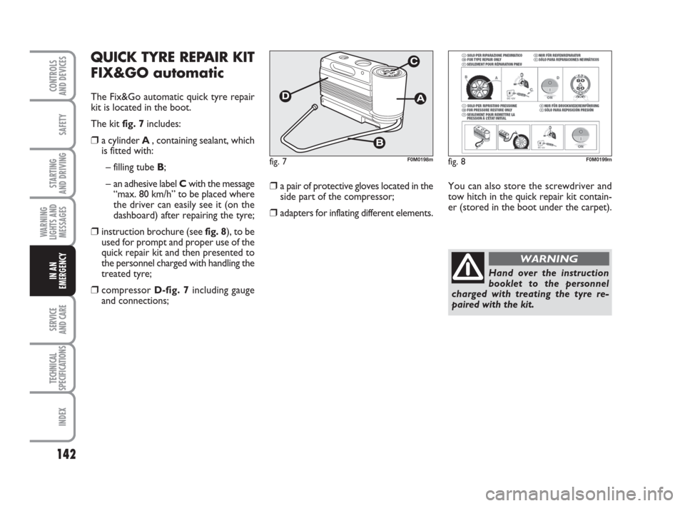
The kit fig. 7includes:
❒a cylinder A , containing sealant, which
is fitted with:
– filling tube B;
– an adhesive label Cwith the message
“max. 80 km/h” to be placed where
the driver can easily see it (on the
dashboard) after repairing the tyre;
❒instruction brochure (see fig. 8), to be
used for prompt and proper use of the
quick repair kit and then presented to
the personnel charged with handling the
treated tyre;
❒compressor D-fig. 7including gauge
and connections;
❒a pair of protective gloves located in the
side part of the compressor;
❒adapters for inflating different elements.
fig. 7F0M0198m
You can also store the screwdriver and
tow hitch in the quick repair kit contain-
er (stored in the boot under the carpet).
fig. 8F0M0199m
Hand over the instruction
booklet to the personnel
charged with treating the tyre re-
paired with the kit.
WARNING
135-166 ACTUAL 1ed EN 26-07-2010 16:00 Pagina 142
Page 153 of 216
152
SAFETY
STARTING
AND DRIVING
WARNING
LIGHTS AND
MESSAGES
SERVICE
AND CARE
TECHNICAL
SPECIFICATIONS
INDEX
CONTROLS
AND DEVICES
IN AN
EMERGENCY
To change the bulb proceed as follows:
❒open the boot then loosen the two fas-
tening screws A;
❒disconnect the central electric connec-
tor and pull the lens unit outwards;
❒loosen the screws Eand remove the
bulb holder;
❒remove the bulb that needs replacing
B, Cor Dby pushing it in slightly and
turning it anti-clockwise (“bayonet”
clamping), then replace it;
❒refit the bulb holder and tighten the
screws E;
❒reconnect the electric connector, cor-
rectly realign the unit with the car body
and then tighten the fastening screws A.
REAR FOG LIGHTS fig. 24
Contact a Fiat Dealership to have bulbs
for the rear fog lights Areplaced.REVERSE LIGHTS fig. 25
Contact a Fiat Dealership to have bulbs
for the reverse lights Areplaced.
fig. 24F0M0208mfig. 25F0M0209m
fig. 23F0M0185m
135-166 ACTUAL 1ed EN 26-07-2010 16:00 Pagina 152
Page 154 of 216
153
SAFETY
STARTING
AND DRIVING
WARNING
LIGHTS AND
MESSAGES
SERVICE
AND CARE
TECHNICAL
SPECIFICATIONS
INDEX
CONTROLS
AND DEVICES
IN AN
EMERGENCY
THIRD BRAKE LIGHT fig. 26-27
To change the bulb proceed as follows:
❒open the boot;
❒remove the rubber caps A-fig. 26;
❒press the catches B-fig. 26and remove
the lens unit C-fig. 27;
❒disconnect the electric connector;
❒press in the tabs D-fig. 27and remove
the bulb holder;
❒remove the snap-fitted bulb and replace
it.
NUMBER PLATE LIGHTS
fig. 28-29
To change the bulb proceed as follows:
❒manipulate the point shown by the ar-
row and remove the lens unit A-fig. 28;
❒change the bulb fig. 29by releasing
it from the side contacts and making
sure the new bulb is correctly fastened
between these contacts;
❒reattach the snap-fitted lens unit.
fig. 26F0M0210mfig. 27F0M0211mfig. 28F0M0212m
fig. 29F0M0233m
135-166 ACTUAL 1ed EN 26-07-2010 16:00 Pagina 153
Page 157 of 216
156
SAFETY
STARTING
AND DRIVING
WARNING
LIGHTS AND
MESSAGES
SERVICE
AND CARE
TECHNICAL
SPECIFICATIONS
INDEX
CONTROLS
AND DEVICES
IN AN
EMERGENCY
ACCESSING THE FUSES
The fuses are grouped in three control
units: on the dashboard, in the engine
compartment and in the left-hand side of
the boot.
Dashboard fusebox fig. 36
To access the dashboard fusebox, loosen
the screws A-fig. 35and remove the
cover.
fig. 36F0M0415m
3 4 5 6 7
8 9 10 11 12
13 141 2
fig. 35F0M0016m
135-166 ACTUAL 1ed EN 26-07-2010 16:00 Pagina 156
Page 159 of 216
158
SAFETY
STARTING
AND DRIVING
WARNING
LIGHTS AND
MESSAGES
SERVICE
AND CARE
TECHNICAL
SPECIFICATIONS
INDEX
CONTROLS
AND DEVICES
IN AN
EMERGENCY
Boot fusebox fig. 40
To access the fusebox located in the left
side of the boot, open the appropriate flap
(as shown infig. 39).
fig. 40F0M0372m
fig. 39F0M0246m
135-166 ACTUAL 1ed EN 26-07-2010 16:00 Pagina 158
Page 160 of 216

159
SAFETY
STARTING
AND DRIVING
WARNING
LIGHTS AND
MESSAGES
SERVICE
AND CARE
TECHNICAL
SPECIFICATIONS
INDEX
CONTROLS
AND DEVICES
IN AN
EMERGENCY
1
8
13
2
5
11
4
6
14
7
12
3
107,5
7,5
5
5
10
5
20
20
20
20
5
5
7,5 FUSE TABLE
Dashboard fusebox fig. 36
DEVICESFUSE AMPS
Right dipped beam headlight
Left dipped beam headlight, corrector, headlamp alignment corrector
INT/A supply for switch coils on engine fusebox
and switch coils on body computer control unit
Front ceiling light, rear ceiling light (VAN version)
Supply and battery for EOBD diagnostic plug, alarm, sound system,
Blue&Me control unit
INT supply for instrument panel, switch on brake pedal
(N.O. contact), third brake light
Door locking/unlocking motors, dead lock activation motors,
boot unlocking motor
Windscreen/rear window washer pump
Electric window motor on driver-side front door
Electric window motor on passenger-side front door
INT supply for dashboard control lights, mirror movement exterior electrics,
sunroof control unit, My Port infotelematic system socket
Instrument panel
INT supply for brake pedal switch (NC contact), clutch pedal switch,
interior heating unit, Blue&Me control unit, sound system capabilities,
voltage stabiliser control unit, reverse light on rear bumper,
water sensor on diesel filter, glow plug heating control unit, airflow meter,
brake booster sensor, switch coils on engine compartment fusebox
135-166 ACTUAL 1ed EN 26-07-2010 16:00 Pagina 159
Page 163 of 216
162
SAFETY
STARTING
AND DRIVING
WARNING
LIGHTS AND
MESSAGES
SERVICE
AND CARE
TECHNICAL
SPECIFICATIONS
INDEX
CONTROLS
AND DEVICES
IN AN
EMERGENCY
17
14
01
03
04
15
10
16
08
07
05
11
13
09
06
0220
7,5
–
–
–
–
20
–
10
–
15
20
–
10
–
– Boot fusebox fig. 44
DEVICESFUSE AMPS
Sunroof opening system
Alarm system management control unit
Spare
Spare
Spare
Spare
Electric windows system (motor, control unit) on right-hand door
Spare
Driver’s seat heater control unit
Tow hook system (capability for after-sale fuse assembly)
Boot socket
Electric windows system (motor, control unit) on left-hand door
Spare
Front passenger seat heater control unit
Spare
Spare
135-166 ACTUAL 1ed EN 26-07-2010 16:00 Pagina 162
Page 166 of 216

165
SAFETY
STARTING
AND DRIVING
WARNING
LIGHTS AND
MESSAGES
SERVICE
AND CARE
TECHNICAL
SPECIFICATIONS
INDEX
CONTROLS
AND DEVICES
IN AN
EMERGENCY
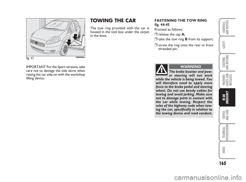
fig. 41F0M0366m
IMPORTANT For the Sport versions, take
care not to damage the side skirts when
raising the car side-on with the workshop
lifting device.
TOWING THE CAR
The tow ring provided with the car is
housed in the tool box under the carpet
in the boot.FASTENING THE TOW RING
fig. 44-45
Proceed as follows:
❒release the cap A;
❒take the tow ring Bfrom its support;
❒screw the ring onto the rear or front
threaded pin.
The brake booster and pow-
er steering will not work
while the vehicle is being towed. You
will therefore need to apply more
force to the brake pedal and steering
wheel. Do not use bendy cables for
towing and avoid jerking. Make sure
not to damage parts in contact with
the car while towing. Respect the
rules of the highway code when tow-
ing the car, specifically in relation to
the towing device and road conduct.
WARNING
135-166 ACTUAL 1ed EN 26-07-2010 16:00 Pagina 165