2014 FIAT GRANDE PUNTO ACTUAL trans
[x] Cancel search: transPage 8 of 216

7
SAFETY
STARTING
AND DRIVING
WARNING
LIGHTS AND
MESSAGES
IN AN
EMERGENCY
SERVICE
AND CARE
TECHNICAL
SPECIFICATIONS
INDEX
CONTROLS
AND DEVICES
In this case, turn the key to STOPand
then back to MAR; try with the other
keys provided if the problem persists.
Contact a Fiat Dealership if you still can-
not start the engine.Warning light Ycoming on
when driving
❒If the warning light Yturns on, this
means that the system is running a self-
test (for example for a voltage drop).
❒If the warning light Ystays on, con-
tact a Fiat Dealership.
The electronic components
inside the key may be dam-
aged if the key is subjected to
sharp knocks.
OPERATION
Each time the vehicle is started turning the
ignition key to MAR, the Fiat CODE sys-
tem control unit sends a recognition code
to the engine control unit to deactivate
the inhibitor.
The code is sent only if the Fiat CODE
system control unit has recognised the
code transmitted from the key.
Each time the ignition key is turned to
STOP, the Fiat CODE system deactivates
the functions of the engine control unit.
If the code has not been recognised cor-
rectly, the warning light
Yturns on ac-
companied by the related message on the
display.
001-032 ACTUAL 1ed EN.qxd 31-08-2010 9:24 Pagina 7
Page 61 of 216

60
SAFETY
STARTING
AND DRIVING
WARNING
LIGHTS AND
MESSAGES
IN AN
EMERGENCY
SERVICE
AND CARE
TECHNICAL
SPECIFICATIONS
INDEX
CONTROLS
AND DEVICES
SKY DOME SUNROOF
(for versions/markets, where provided)
The large electric sunroof comprises two
panes of glass, one of which is mobile and
the other fixed. These are equipped with
two shutters (front and rear) that can be
moved manually. The shutters can be used
in the “fully closed” or “fully open” posi-
tions (they have no fixed intermediate po-
sitions). To open the shutters: grip handle
A-fig. 68, release it and move it in the
direction of the arrows to the “fully open”
position. To close them, carry out the
procedure in reverse. The sunroof can be
operated only when the ignition key is
turned to MAR. The controls A-B fig. 67
on a dedicated dashboard near the front
ceiling lights open and close the sunroof.
To open
Press and hold button B-fig. 67, and the
front pane will set to the “spoiler” posi-
tion; press button B-fig. 67 again for over
half a second to make the sunroof slide au-
tomatically to the wide open position;
press the button once more to stop the
sunroof at an intermediate position.To close
When in wide open position, press but-
ton A-fig. 67for over half a second to set
the front pane to the “spoiler” position;
press the button again to stop the sunroof
at an intermediate position; press button
A-fig. 67once more and hold it down to
close the sunroof completely.
fig. 67
A
B
F0M0087m
Use the sunroof only at
“spoiler” position if a trans-
verse roof rack is fitted.
Do not open the sunroof if
there is snow or ice: it could
be damaged.
When leaving the car, al-
ways remove the key from
the ignition to avoid the risk of injury
due to accidental operation of the
sunroof. Improper use of the roof can
be dangerous. Before operation, al-
ways check that no-one is at risk of
being injured by the moving sunroof
or by objects getting caught and
dragged by it.
WARNING
fig. 68F0M0172m
033-071 ACTUAL 1ed EN 21-07-2010 14:25 Pagina 60
Page 65 of 216
64
SAFETY
STARTING
AND DRIVING
WARNING
LIGHTS AND
MESSAGES
IN AN
EMERGENCY
SERVICE
AND CARE
TECHNICAL
SPECIFICATIONS
INDEX
CONTROLS
AND DEVICES
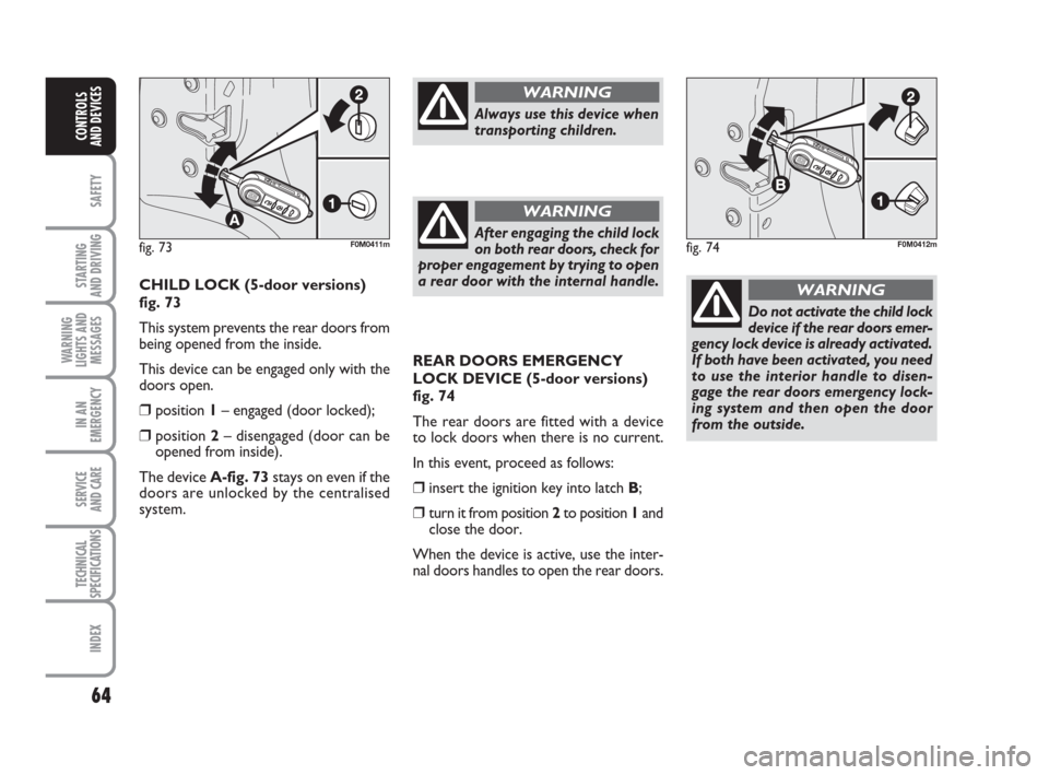
REAR DOORS EMERGENCY
LOCK DEVICE (5-door versions)
fig. 74
The rear doors are fitted with a device
to lock doors when there is no current.
In this event, proceed as follows:
❒insert the ignition key into latch B;
❒turn it from position 2 to position 1and
close the door.
When the device is active, use the inter-
nal doors handles to open the rear doors.
Do not activate the child lock
device if the rear doors emer-
gency lock device is already activated.
If both have been activated, you need
to use the interior handle to disen-
gage the rear doors emergency lock-
ing system and then open the door
from the outside.
WARNINGCHILD LOCK (5-door versions)
fig. 73
This system prevents the rear doors from
being opened from the inside.
This device can be engaged only with the
doors open.
❒position 1– engaged (door locked);
❒position 2– disengaged (door can be
opened from inside).
The device A-fig. 73stays on even if the
doors are unlocked by the centralised
system.
Always use this device when
transporting children.
WARNING
After engaging the child lock
on both rear doors, check for
proper engagement by trying to open
a rear door with the internal handle.
WARNING
fig. 74F0M0412mfig. 73F0M0411m
033-071 ACTUAL 1ed EN 21-07-2010 14:26 Pagina 64
Page 73 of 216
72
SAFETY
STARTING
AND DRIVING
WARNING
LIGHTS AND
MESSAGES
IN AN
EMERGENCY
SERVICE
AND CARE
TECHNICAL
SPECIFICATIONS
INDEX
CONTROLS
AND DEVICES
HEADLIGHTS
LIGHT BEAM DIRECTION
The correct direction of the headlights is
essential for the comfort and safety of the
driver and other road users. The head-
lights must be correctly directed to ensure
the best visibility. Contact a Fiat Dealer-
ship to have the direction checked and, if
necessary, adjusted.
HEADLIGHT ALIGNMENT
CORRECTOR
This device works with the key atMAR
and the dipped beam headlights on. The
car will slant backwards when it is loaded,
raising the light beam. The beams must
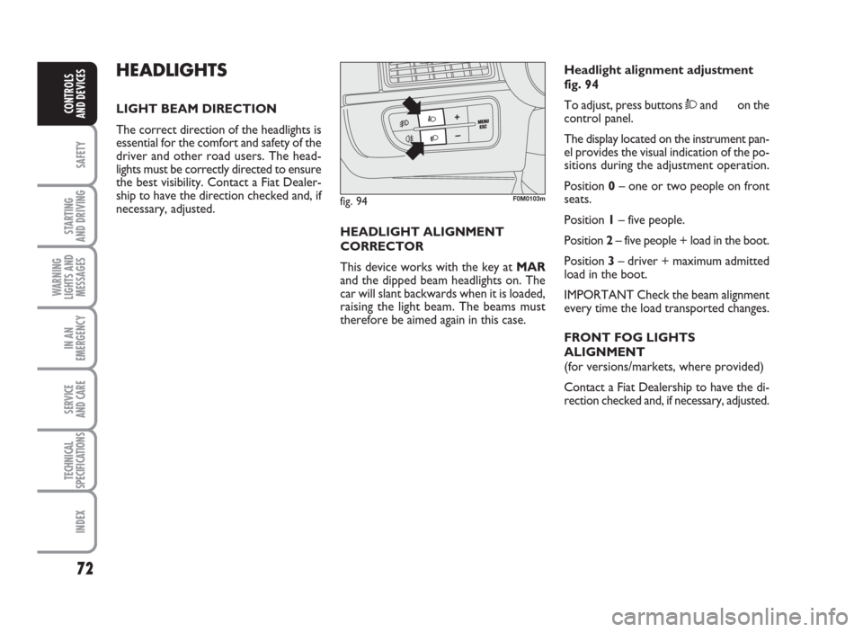
therefore be aimed again in this case.Headlight alignment adjustment
fig. 94
To adjust, press buttonsÒand on the
control panel.
The display located on the instrument pan-
el provides the visual indication of the po-
sitions during the adjustment operation.
Position0– one or two people on front
seats.
Position1– five people.
Position2– five people + load in the boot.
Position3– driver + maximum admitted
load in the boot.
IMPORTANT Check the beam alignment
every time the load transported changes.
FRONT FOG LIGHTS
ALIGNMENT
(for versions/markets, where provided)
Contact a Fiat Dealership to have the di-
rection checked and, if necessary, adjusted.
fig. 94F0M0103m
072-092 ACTUAL 1ed EN 26-07-2010 10:54 Pagina 72
Page 78 of 216
77
SAFETY
STARTING
AND DRIVING
WARNING
LIGHTS AND
MESSAGES
IN AN
EMERGENCY
SERVICE
AND CARE
TECHNICAL
SPECIFICATIONS
INDEX
CONTROLS
AND DEVICES
MSR system
(engine braking regulation)
This is an integral part of the ASR system
that, in case of sudden gear shifting, cuts
in to provide torque to the engine, thus
preventing excessive driving wheel drag
that, especially in poor grip conditions, can
lead to loss of stability.
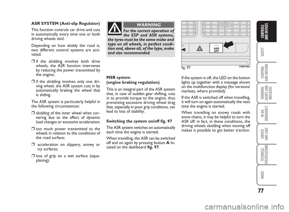
Switching the systemon/off fig. 97
The ASR system switches on automatically
each time the engine is started.
When travelling, the ASR can be switched
off and on again by pressing buttonAlo-
cated on the dashboardfig. 97.If the system is off, the LED on the button
lights up together with a message shown
on the multifunction display (for versions/
markets, where provided).
If the ASR is switched off when travelling,
it will turn on again automatically the next
time the engine is started.
When travelling on snowy roads with
snow chains, it may be helpful to turn the
ASR off: in fact, in these conditions, the
driving wheels skidding when moving off
makes it possible to get better traction.
For the correct operation of
the ESP and ASR systems,
the tyres must be the same make and
type on all wheels, in perfect condi-
tion and, above all, of the type, make
and size recommended.
WARNING
fig. 97
ASR
OFF
F0M0109m
ASR SYSTEM (Anti-slip Regulator)
This function controls car drive and cuts
in automatically every time one or both
driving wheels skid.
Depending on how skiddy the road is,
two different control systems are acti-
vated:
❒if the skidding involves both drive
wheels, the ASR function intervenes
by reducing the power transmitted by
the engine;
❒if the skidding involves only one dri-
ving wheel, the ASR system cuts in by
automatically braking the wheel that
is sliding.
The ASR system is particularly helpful in
the following circumstances:
❒skidding of the inner wheel when cor-
nering due to the effect of dynamic
load changes or excessive acceleration;
❒too much power transmitted to the
wheels in relation to the conditions of
the road surface;
❒acceleration on slippery, snowy or
icy surfaces;
❒loss of grip on a wet surface (aqua-
planing).
072-092 ACTUAL 1ed EN 26-07-2010 10:55 Pagina 77
Page 82 of 216
81
SAFETY
STARTING
AND DRIVING
WARNING
LIGHTS AND
MESSAGES
IN AN
EMERGENCY
SERVICE
AND CARE
TECHNICAL
SPECIFICATIONS
INDEX
CONTROLS
AND DEVICES
fig. 99F0M0505m
START&STOP SYSTEM
(for versions/markets, where provided)
FOREWORD
The Start&Stop device automatically stops
the engine each time the vehicle is sta-
tionary and starts it again when the driver
wants to move off.
This improves the efficiency of the vehicle
by reducing fuel consumption, the emis-
sion of harmful gases and noise pollution.
The system is activated each time the car
is started.
OPERATING MODES
Engine cut-out mode
With manual transmission
With the vehicle stationary, the engine
cuts out with the gearbox in neutral and
the clutch pedal released.With Dualogic gearbox
(for versions/markets, where provided)
The engine cuts out if the car stops with
the brake pedal pressed.
This condition can be maintained even if
the brake pedal is not pressed, if the gear
lever is in position N.
NB: The engine can be stopped automat-
ically only after a speed of about 10 Km/h
is reached, to prevent the engine from be-
ing repeatedly stopped when driving at
walking pace.
The engine being stopped is signalled by
the warning lightfig. 99on the instrument
panel, depending on the configuration.Engine restarting mode
With normal transmission
Press the clutch pedal to allow the engine
to be restarted.
With Dualogic gearbox
(for versions/markets, where provided)
If the gear lever is in position N, place it
in any other gear, otherwise release the
brake pedal or move the gear lever to (+),
(–) or R .
072-092 ACTUAL 1ed EN 26-07-2010 10:55 Pagina 81
Page 86 of 216
85
SAFETY
STARTING
AND DRIVING
WARNING
LIGHTS AND
MESSAGES
IN AN
EMERGENCY
SERVICE
AND CARE
TECHNICAL
SPECIFICATIONS
INDEX
CONTROLS
AND DEVICES
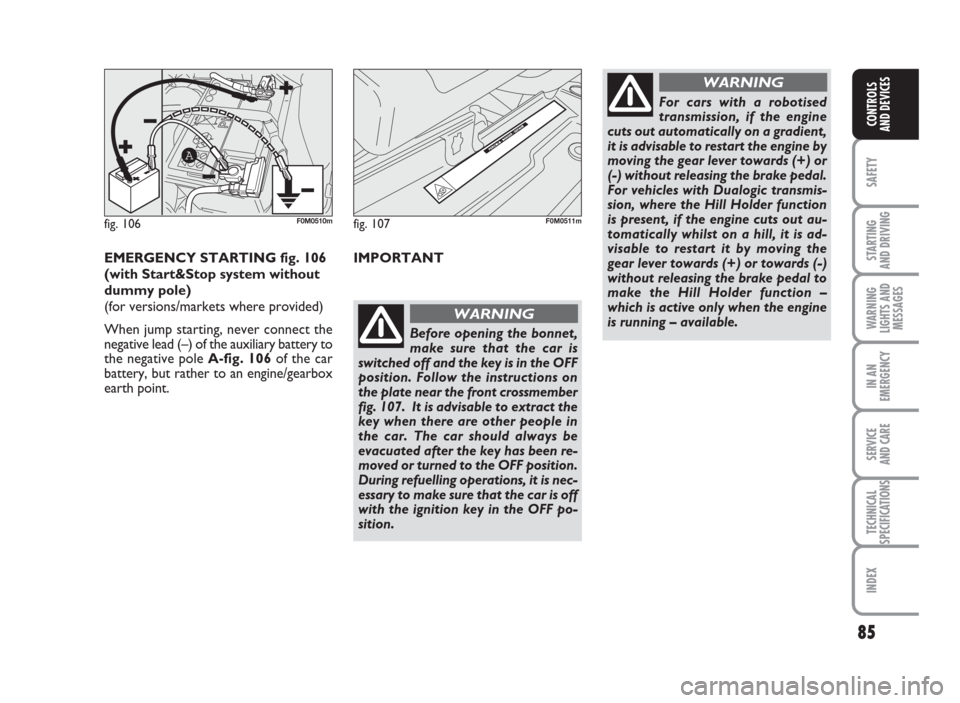
fig. 106
A
F0M0510mfig. 107F0M0511m
EMERGENCY STARTING fig. 106
(with Start&Stop system without
dummy pole)
(for versions/markets where provided)
When jump starting, never connect the
negative lead (–) of the auxiliary battery to
the negative poleA-fig. 106of the car
battery, but rather to an engine/gearbox
earth point.IMPORTANT
Before opening the bonnet,
make sure that the car is
switched off and the key is in the OFF
position. Follow the instructions on
the plate near the front crossmember
fig. 107. It is advisable to extract the
key when there are other people in
the car. The car should always be
evacuated after the key has been re-
moved or turned to the OFF position.
During refuelling operations, it is nec-
essary to make sure that the car is off
with the ignition key in the OFF po-
sition.
WARNING
For cars with a robotised
transmission, if the engine
cuts out automatically on a gradient,
it is advisable to restart the engine by
moving the gear lever towards (+) or
(-) without releasing the brake pedal.
For vehicles with Dualogic transmis-
sion, where the Hill Holder function
is present, if the engine cuts out au-
tomatically whilst on a hill, it is ad-
visable to restart it by moving the
gear lever towards (+) or towards (-)
without releasing the brake pedal to
make the Hill Holder function –
which is active only when the engine
is running – available.
WARNING
072-092 ACTUAL 1ed EN 26-07-2010 10:55 Pagina 85
Page 90 of 216
89
SAFETY
STARTING
AND DRIVING
WARNING
LIGHTS AND
MESSAGES
IN AN
EMERGENCY
SERVICE
AND CARE
TECHNICAL
SPECIFICATIONS
INDEX
CONTROLS
AND DEVICES
RADIO TRANSMITTERS
ANDMOBILEPHONES
Radio transmitter equipment (vehicle mo-
bile phones, CB radios, amateur radio etc.)
shall not be used inside the car unless
a separate aerial is mounted on the roof.
IMPORTANT The use of these devices in-
side the passenger compartment (without
a separate aerial) may cause the vehicle
electrical systems to malfunction. This
could compromise safety in addition to
constituting a potential hazard for pas-
sengers’ health.
In addition, transmission and reception of
these devices may be affected by the
shielding effect of the car body.
With regard to EC-approved mobile
phones (GSM, GPRS, UMTS), you should
adhere strictly to the instructions provid-
ed by the mobile phone’s manufacturer.
Take care when fitting addi-
tional spoilers, alloy wheels
or non-standard wheel hubs: they
could reduce the ventilation of the
brakes and affect efficiency under
sharp, repeated braking or on long
descents. Make sure that nothing ob-
structs the pedals (mats, etc.)
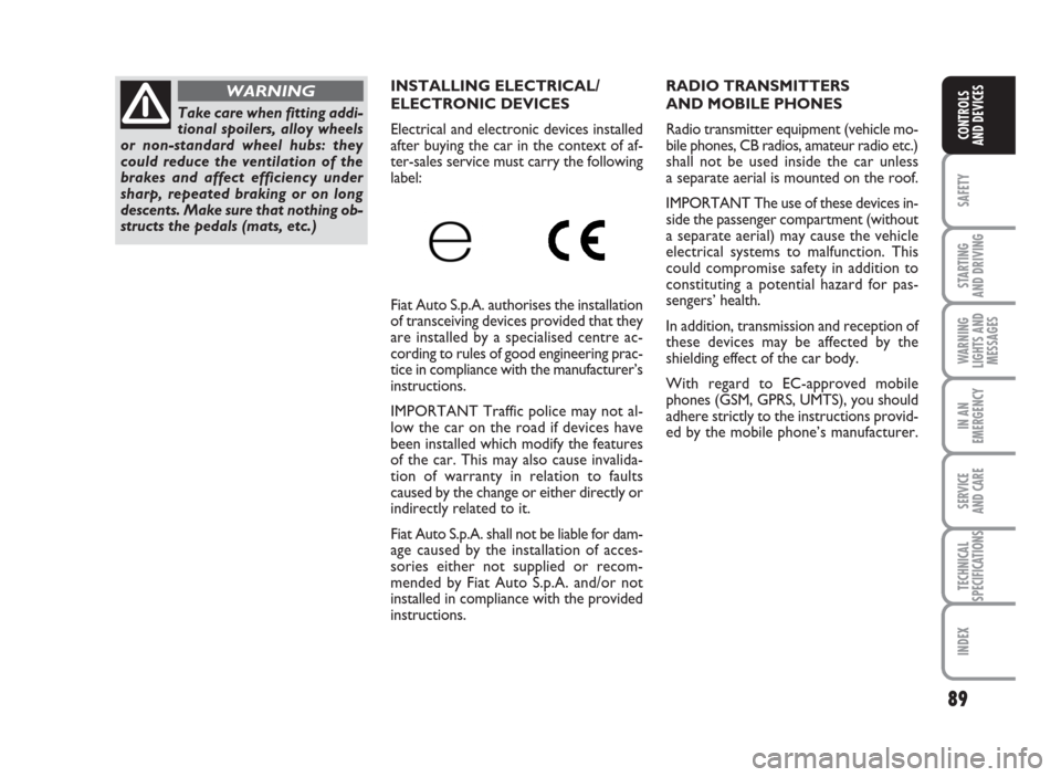
WARNINGINSTALLING ELECTRICAL/
ELECTRONIC DEVICES
Electrical and electronic devices installed
after buying the car in the context of af-
ter-sales service must carry the following
label:
Fiat Auto S.p.A. authorises the installation
of transceiving devices provided that they
are installed by a specialised centre ac-
cording to rules of good engineering prac-
tice in compliance with the manufacturer’s
instructions.
IMPORTANT Traffic police may not al-
low the car on the road if devices have
been installed which modify the features
of the car. This may also cause invalida-
tion of warranty in relation to faults
caused by the change or either directly or
indirectly related to it.
Fiat Auto S.p.A. shall not be liable for dam-
age caused by the installation of acces-
sories either not supplied or recom-
mended by Fiat Auto S.p.A. and/or not
installed in compliance with the provided
instructions.
072-092 ACTUAL 1ed EN 26-07-2010 10:55 Pagina 89