Page 71 of 275
Cooled drinks compartment
Press button A fig. 51 and lift up armrest B: you can
then access the cooled drinks compartment fig. 52.
IMPORTANT The function of the compartment is to
maintain the temperature of the drinks that are put
in, which should be heated or cooled beforehand.REAR ARMREST
(for versions/markets, where provided)
To use armrest A fig. 53, lower it as shown in the
diagram.
fig. 51
F0Q0634
fig. 52
F0Q0633
fig. 53
F0Q0010
67GETTING TO
KNOW YOUR CARSAFETY
STARTING AND
DRIVING
WARNING LIGHTS
AND MESSAGES
IN AN EMERGENCY
SERVICING AND
MAINTENANCE
TECHNICAL
SPECIFICATIONS
INDEX
Page 122 of 275

FITTING "UNIVERSAL"
CHILD RESTRAINT SYSTEM
(with seat belts)GROUP 0 and 0+
WARNING
The diagram is indicative and for fitting
purposes only. Fit the child restraint
system according to the instructions, which must
be included.
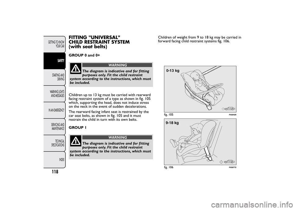
Children up to 13 kg must be carried with rearward
facing restraint system of a type as shown in fig. 105
which, supporting the head, does not induce stress
on the neck in the event of sudden decelerations.
The rearward facing infant seat is restrained by the
car seat belts, as shown in fig. 105 and it must
restrain the child in turn with its own belts.
GROUP 1
WARNING
The diagram is indicative and for fitting
purposes only. Fit the child restraint
system according to the instructions, which must
be included.Children of weight from 9 to 18 kg may be carried in
forward facing child restraint systems fig. 106.
fig. 105
F0Q0429
fig. 106
F0Q0772
118GETTING TO KNOW
YOUR CAR
SAFETY
STARTING AND
DRIVING
WARNING LIGHTS
AND MESSAGES
IN AN EMERGENCY
SERVICING AND
MAINTENANCE
TECHNICAL
SPECIFICATIONS
INDEX
Page 123 of 275
WARNING
Child restraint systems with Isofix
attachments are available for a safe
anchoring to the seat without using the car seat
belts.
GROUP 2
WARNING
The diagram is indicative and for fitting
purposes only. Fit the child restraint
system according to the instructions, which must
be included.Children from 15 to 25 kg may use the car seat belts
directly fig. 107.
In this case, the child restraint system is used to
position the child correctly with respect to the seat
belts so that the diagonal belt section crosses the
child’s chest and not the neck, and the lower part is
snug on the pelvis not the abdomen.
fig. 107
F0Q0431
119GETTING TO KNOW
YOUR CARSAFETYSTARTING AND
DRIVING
WARNING LIGHTS
AND MESSAGES
IN AN EMERGENCY
SERVICING AND
MAINTENANCE
TECHNICAL
SPECIFICATIONS
INDEX
Page 124 of 275
GROUP 3
WARNING
The diagram is indicative and for fitting
purposes only. Fit the child restraint
system according to the instructions, which must
be included.
For children between 22 kg and 36 kg, there are
dedicated restraint systems that allow the seat belt
to be worn correctly.The fig. 108 shows the correct child positioning on
the rear seat.
Children over 1.50 m in height can wear seat belts
like adults.
fig. 108
F0Q0432
120GETTING TO KNOW
YOUR CAR
SAFETY
STARTING AND
DRIVING
WARNING LIGHTS
AND MESSAGES
IN AN EMERGENCY
SERVICING AND
MAINTENANCE
TECHNICAL
SPECIFICATIONS
INDEX
Page 126 of 275
ISOFIX CHILD RESTRAINT SYSTEM
SETUPThe car is equipped with ISOFIX anchorages, a new
standard which makes fitting a child restraint system
quick, simple and safe.
Isofix systems can be fitted alongside conventional
child restraint systems on different seats in the same
car.
fig. 109An example of a Universal Isofix child
restraint system for weight group 1.
WARNING
The diagram is indicative and for fitting
purposes only. Fit the child restraint
system according to the instructions, which must
be included.
The other weight groups are covered by specific
Isofix child restraint systems, which can be used only
if specifically tested for this car (see list of cars
provided with the child restraint system).
fig. 109
F0Q0614
122GETTING TO KNOW
YOUR CAR
SAFETY
STARTING AND
DRIVING
WARNING LIGHTS
AND MESSAGES
IN AN EMERGENCY
SERVICING AND
MAINTENANCE
TECHNICAL
SPECIFICATIONS
INDEX
Page 142 of 275

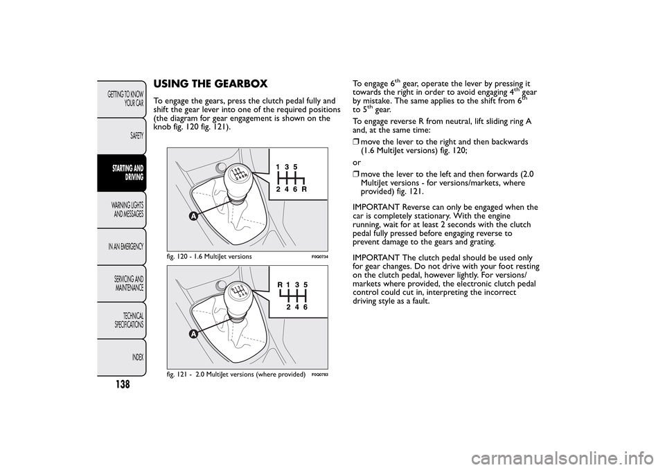
USING THE GEARBOXTo engage the gears, press the clutch pedal fully and
shift the gear lever into one of the required positions
(the diagram for gear engagement is shown on the
knob fig. 120 fig. 121).To engage 6
th
gear, operate the lever by pressing it
towards the right in order to avoid engaging 4
th
gear
by mistake. The same applies to the shift from 6th
to 5
th
gear.
To engage reverse R from neutral, lift sliding ring A
and, at the same time:
❒move the lever to the right and then backwards
(1.6 MultiJet versions) fig. 120;
or
❒move the lever to the left and then forwards (2.0
MultiJet versions - for versions/markets, where
provided) fig. 121.
IMPORTANT Reverse can only be engaged when the
car is completely stationary. With the engine
running, wait for at least 2 seconds with the clutch
pedal fully pressed before engaging reverse to
prevent damage to the gears and grating.
IMPORTANT The clutch pedal should be used only
for gear changes. Do not drive with your foot resting
on the clutch pedal, however lightly. For versions/
markets where provided, the electronic clutch pedal
control could cut in, interpreting the incorrect
driving style as a fault.
fig. 120 - 1.6 MultiJet versions
F0Q0734
fig. 121 - 2.0 MultiJet versions (where provided)
F0Q0783
138GETTING TO KNOW
YOUR CAR
SAFETYSTARTING AND
DRIVINGWARNING LIGHTS
AND MESSAGES
IN AN EMERGENCY
SERVICING AND
MAINTENANCE
TECHNICAL
SPECIFICATIONS
INDEX
Page 170 of 275

❒fit handle R fig. 127 to operate the jack and raise
the car until the wheel is a few centimetres above
the ground;
❒fully loosen the fastening bolts and remove the
wheel.
❒make sure the contact surfaces between
space-saver wheel and hub are clean so that the
fastening bolts will not come loose;
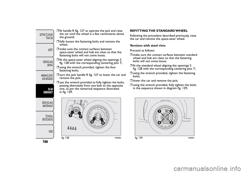
❒fit the space-saver wheel aligning the openings S
fig. 128 with the corresponding centering pins T;
❒using the wrench provided, tighten the four
fastening bolts;
❒turn the jack handle R fig. 127 to lower the car and
remove the jack;
❒use the wrench provided to fully tighten the bolts,
passing alternately from one bolt to the opposite
one, as per the numerical sequence illustrated
in fig. 129.REFITTING THE STANDARD WHEEL
Following the procedure described previously, raise
the car and remove the space-saver wheel.
Versions with steel rims
Proceed as follows:
❒make sure the contact surfaces between standard
wheel and hub are clean so that the fastening
bolts will not come loose;
❒fit the standard wheel aligning the openings S
fig. 128 with the corresponding centering pins T;
❒using the wrench provided, tighten the fastening
bolts;
❒lower the car and remove the jack;
❒using the wrench provided, fully tighten the bolts
in the sequence shown in diagram fig. 129;
fig. 128
F0Q0396
fig. 129
F0Q0397
166GETTING TO KNOW
YOUR CAR
SAFETY
STARTING AND
DRIVING
WARNING LIGHTS
AND MESSAGES
IN AN
EMERGENCY
SERVICING AND
MAINTENANCE
TECHNICAL
SPECIFICATIONS
INDEX